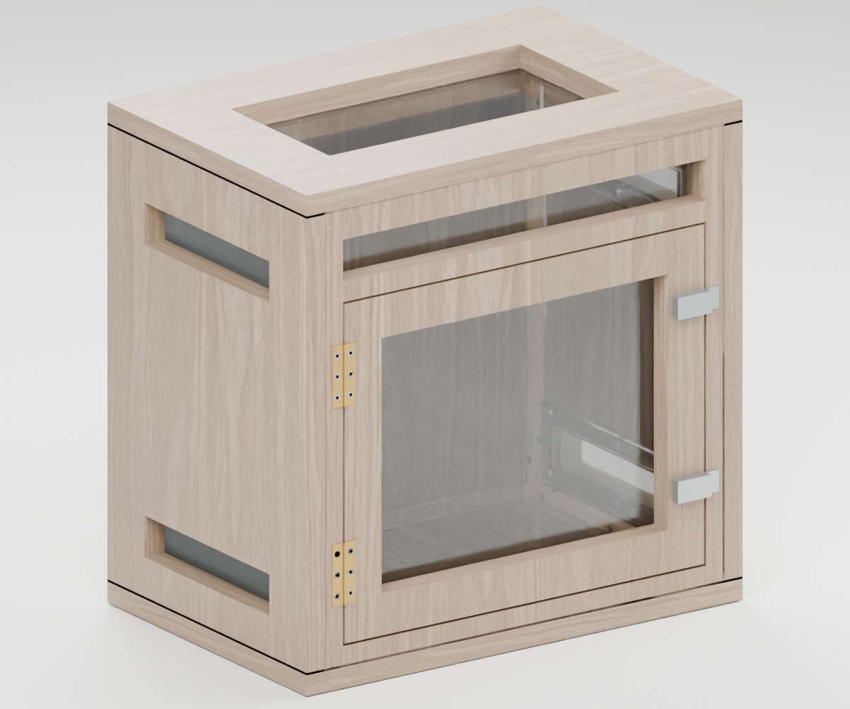
Tap a finish, then select the enclosure to enlarge.
White oak veneer
Natural colour and grain vary. Oak is the specified appearance; maple and walnut require separate stock/finish checks. The construction viewer shows oak.
For one adult regal jumping spider, Phidippus regius. Oak covers the roof, faces and exposed edges. The fine side screens and continuous door seal require physical verification.
Review design only: material, hardware, seal, prototype and species-review holds remain. Do not cut production parts or introduce an animal while the relevant holds are open.
This is a small precision woodworking project with custom acrylic parts. Arrange competent routing/drilling help if you cannot safely hold the narrow parts. Work with an empty enclosure only.
Dimension or limit
Meaning
12 × 8 × 12 in (304.8 × 203.2 × 304.8 mm)
Finished wood case; latch projects another 0.244 in (6.2 mm) in front.
9.8 × 6 × 9.75 in (248.92 × 152.4 × 247.65 mm)
Conservative usable box above a floor layer up to 1/2 in (12.7 mm). Furnishings reduce free space.
Minimum comparison
Clears the current 6 × 6 × 9-inch (152.4 × 152.4 × 228.6 mm) adult baseline on paper. This is not an experimental welfare threshold.
Preferred comparison
Does not meet the 8 × 8 × 12-inch (203.2 × 203.2 × 304.8 mm) preferred usable target.
Load scenario
Up to 2.2 lb (1 kg) contents is a design scenario, not tested capacity. No roof load, stacking, immersion or animal transport.
Glossary
PSA = pressure-sensitive adhesive; RH = relative humidity; mm = millimetres; kerf = saw-cut width; reveal = visible door clearance; pilot = starting hole in receiving wood.
H01–H07 are listed in the final records. Missing supplier dimensions are not permission to improvise. Retain the labelled trial pieces and measured records.
Tools and a safe workspace
THE CREATURE CORNER · SP-SLIM-01 · REVIEW DESIGN
Task
Prepare
Measuring
Caliper, steel rule, square, straightedge, tape, feeler/transfer materials, labels and a flat bench.
Wood machining
Guarded saw and guide; safely clamped router templates or a CNC supplier; sacrificial backer, extraction, eye/hearing protection.
Drilling
Depth stops, pilot/clearance bits proven on offcuts, acrylic-compatible bits, countersink only after a successful coupon.
Assembly
Padded clamps, right-angle supports, hand screwdrivers, small plastic-safe deburring tools and mesh shears/gloves.
Finishing
Exact selected products and current labels/SDS; brush/scraper; suitable ventilation and temperature/RH log.
Animal handoff
Secure holding enclosure, inspection magnifier/light, temperature/RH instruments and qualified species reviewer.
Do not handhold small pieces near a blade or cutter. Do not use the animal to test containment. Unplug tools before changing bits and follow their actual manuals.
Active work, supplier lead time, cure time, commissioning and review are separate. No total completion time is promised.
Shopping and cutting references precede the steps. Exact part drawings, station patterns, records and evidence follow them. The downloadable CSVs preserve every individual station.
Shopping list
THE CREATURE CORNER · SP-SLIM-01 · REVIEW DESIGN
Material sourcing
M01 · 50-mesh 316 stainless woven wire, RU50-009J
Four installed blanks; request one 24 × 12-inch (610 × 305 mm) cut sheet. Quote and aperture certificate required.
No maximum aperture tolerance confirmed; request certificate and inspect received sheet. No order placed.
G01 · Rogers BISCO BF-1000 white silicone foam, custom one-piece ring with converter-applied PSA backing
One custom die-cut ring installed plus one spare; dimensions in G01 drawing; supplier quote/tolerance required.
Exact backing adhesive identity, compatibility, bond method and thickness remain H03/H05. Backing must be fully covered by the ring, with no loose/exposed adhesive edge. The 0.005-inch backing model is a planning envelope only. Not an animal-contact approval.
One small cartridge for trials and perimeter beads; exact bead volume/compatibility must be confirmed.
Nonstructural perimeter seal only. Aquarium claim is not species-specific approval. Use plastic supplier-compatible cleaners; do not expose acrylic to acetone.
V01 · Oakwood flat-cut white oak with 3M PSA backer
One 48 × 96-inch (1219 × 2438 mm) sheet, selected PSA backer; balance faces and cut matching edges.
Confirm ordered backer, thickness and compatibility; total 0.030-inch face allowance in design is a measured-stack target, not a vendor specification. Balance both faces.
One quart (946 mL) is a purchase allowance, subject to exact label coverage, coat count and coupon demand; exact SKU/cure held.
Confirm exact SKU/current full-cure label before purchase. Full-cure duration not established by this page; H05 remains open. No shortcut based on odour or touch-dry condition.
Buy one 24 × 48-inch (610 × 1219 mm) plywood sheet with an actual 1/2-inch (12.7 mm) core only after H01. Exact plywood supplier/grade remains unselected. Reject unsuitable stock rather than accepting its nominal label.
Eight 5/8 × 3/8 × 24-inch rough straight-grain cleat blanks (15.875 × 9.525 × 609.6 mm), to finish at 3/8-inch square. Also buy one 1/2 × 1/4 × 24-inch spacer blank (12.7 × 6.35 × 609.6 mm); plane its thickness to the measured seal setup before separating spacers. These allowances cover the listed rough widths, 1/8-inch (3.175 mm) kerf and trials. Have a supplier prepare them or machine larger safely held stock; do not handhold tiny pieces.
Screw family
Installed / purchase allowance
#2 × 3/8-inch flat-head brass, provisional hinge length
12 / 16
#4 × 3/8-inch stainless flat-head
16 / 20
#4 × 1/2-inch stainless, acrylic keeper
44 / 51
#4 × 5/8-inch stainless, door-stop spacers
10 / 14
#4 × 3/4-inch stainless flat-head cleat screws
48 / 56
Also allow eight smooth washers for the fixed transom, protective masking, abrasives and glue/finish trial stock. Screw/washer supplier SKUs and hinge count must be confirmed at receiving; these are not a released shopping cart. No affiliate link or live price is invented.
Cut list
THE CREATURE CORNER · SP-SLIM-01 · REVIEW DESIGN
Part cuts
Quantity one per ID. Long × short × thickness. G01 uses nominal free foam thickness, before compression; its backing is supplied separately by the converter. Rough blanks include 1/4-inch (6.35 mm) trim on both long/short dimensions; the final fit is from released stock, not the nominal label. Hole positions follow the part drawings.
Quantity one per ID. Long × short × thickness. G01 uses nominal free foam thickness, before compression; its backing is supplied separately by the converter. Rough blanks include 1/4-inch (6.35 mm) trim on both long/short dimensions; the final fit is from released stock, not the nominal label. Hole positions follow the part drawings.
Quantity one per ID. Long × short × thickness. G01 uses nominal free foam thickness, before compression; its backing is supplied separately by the converter. Rough blanks include 1/4-inch (6.35 mm) trim on both long/short dimensions; the final fit is from released stock, not the nominal label. Hole positions follow the part drawings.
Quantity one per ID. Long × short × thickness. G01 uses nominal free foam thickness, before compression; its backing is supplied separately by the converter. Rough blanks include 1/4-inch (6.35 mm) trim on both long/short dimensions; the final fit is from released stock, not the nominal label. Hole positions follow the part drawings.
Part / material
Rough blank
Finished reference
RL2 · Vent retaining ring L2 acrylic
6.15 × 2.15 × 0.118 in (156.21 × 54.61 × 3 mm)
5.9 × 1.9 × 0.118 in (149.86 × 48.26 × 3 mm)
AR · Side splash panel R acrylic
10.35 × 6.35 × 0.118 in (262.89 × 161.29 × 3 mm)
10.1 × 6.1 × 0.118 in (256.54 × 154.94 × 3 mm)
MR1 · Fine mesh R1 mesh
5.95 × 1.95 × 0.018 in (151.13 × 49.53 × 0.46 mm)
5.7 × 1.7 × 0.018 in (144.78 × 43.18 × 0.46 mm)
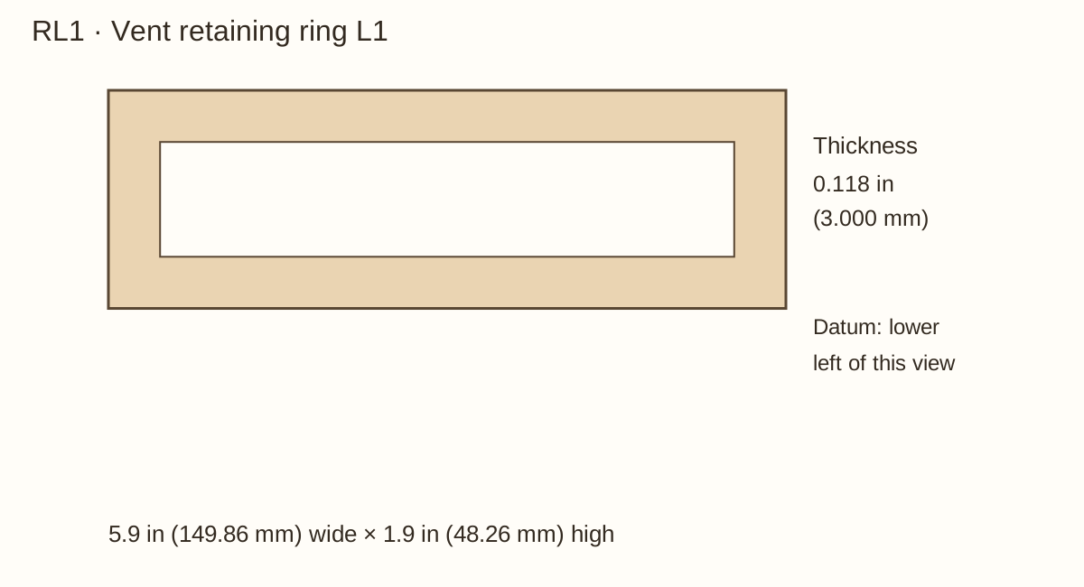
RR1 · Vent retaining ring R1 acrylic
6.15 × 2.15 × 0.118 in (156.21 × 54.61 × 3 mm)
5.9 × 1.9 × 0.118 in (149.86 × 48.26 × 3 mm)
MR2 · Fine mesh R2 mesh
5.95 × 1.95 × 0.018 in (151.13 × 49.53 × 0.46 mm)
5.7 × 1.7 × 0.018 in (144.78 × 43.18 × 0.46 mm)
RR2 · Vent retaining ring R2 acrylic
6.15 × 2.15 × 0.118 in (156.21 × 54.61 × 3 mm)
5.9 × 1.9 × 0.118 in (149.86 × 48.26 × 3 mm)
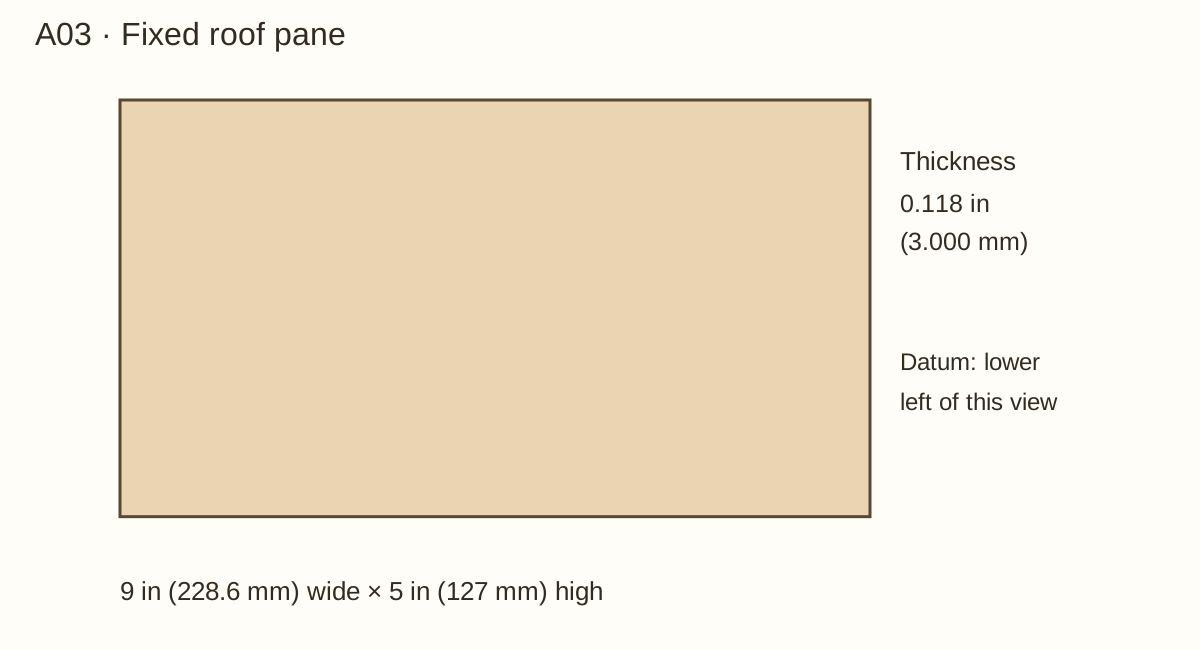
A03 · Fixed roof pane acrylic
9.25 × 5.25 × 0.118 in (234.95 × 133.35 × 3 mm)
9 × 5 × 0.118 in (228.6 × 127 × 3 mm)
THE CREATURE CORNER · SP-SLIM-01 · REVIEW DESIGN
Part cuts · continued
Quantity one per ID. Long × short × thickness. G01 uses nominal free foam thickness, before compression; its backing is supplied separately by the converter. Rough blanks include 1/4-inch (6.35 mm) trim on both long/short dimensions; the final fit is from released stock, not the nominal label. Hole positions follow the part drawings.
Part / material
Rough blank
Finished reference
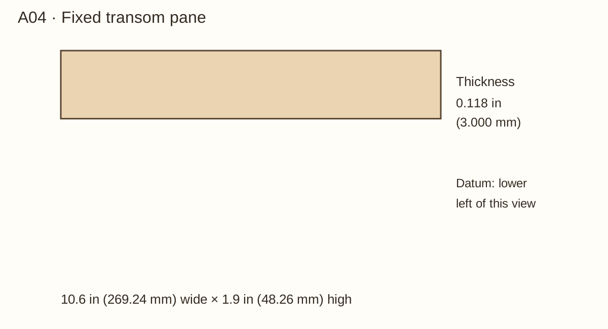
A04 · Fixed transom pane acrylic
10.85 × 2.15 × 0.118 in (275.59 × 54.61 × 3 mm)
10.6 × 1.9 × 0.118 in (269.24 × 48.26 × 3 mm)
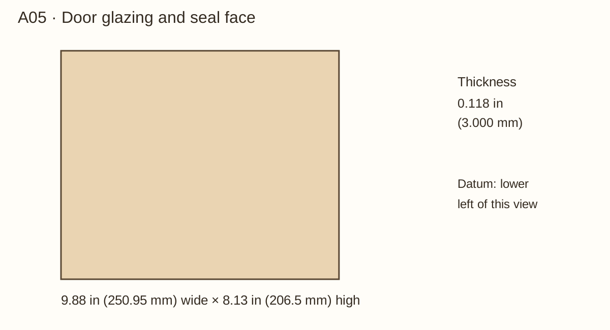
A05 · Door glazing and seal face acrylic
10.13 × 8.38 × 0.118 in (257.3 × 212.85 × 3 mm)
9.88 × 8.13 × 0.118 in (250.95 × 206.5 × 3 mm)
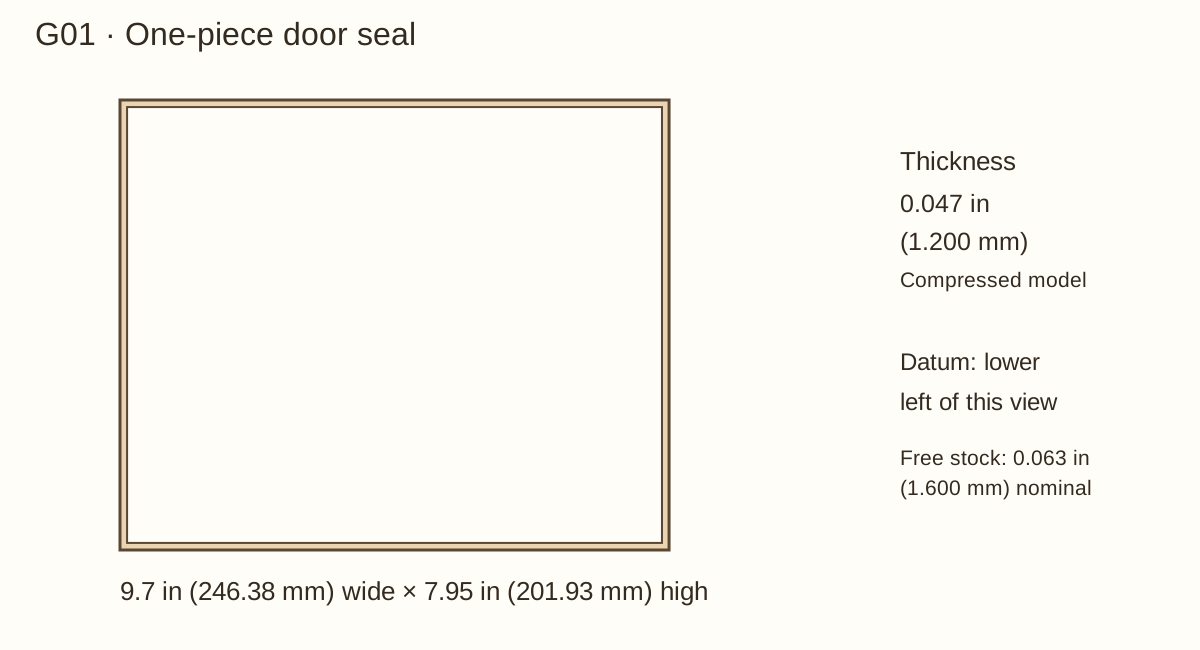
G01 · One-piece door seal gasket
9.95 × 8.2 × 0.063 in (252.73 × 208.28 × 1.6 mm)
9.7 × 7.95 × 0.063 in (246.38 × 201.93 × 1.6 mm)
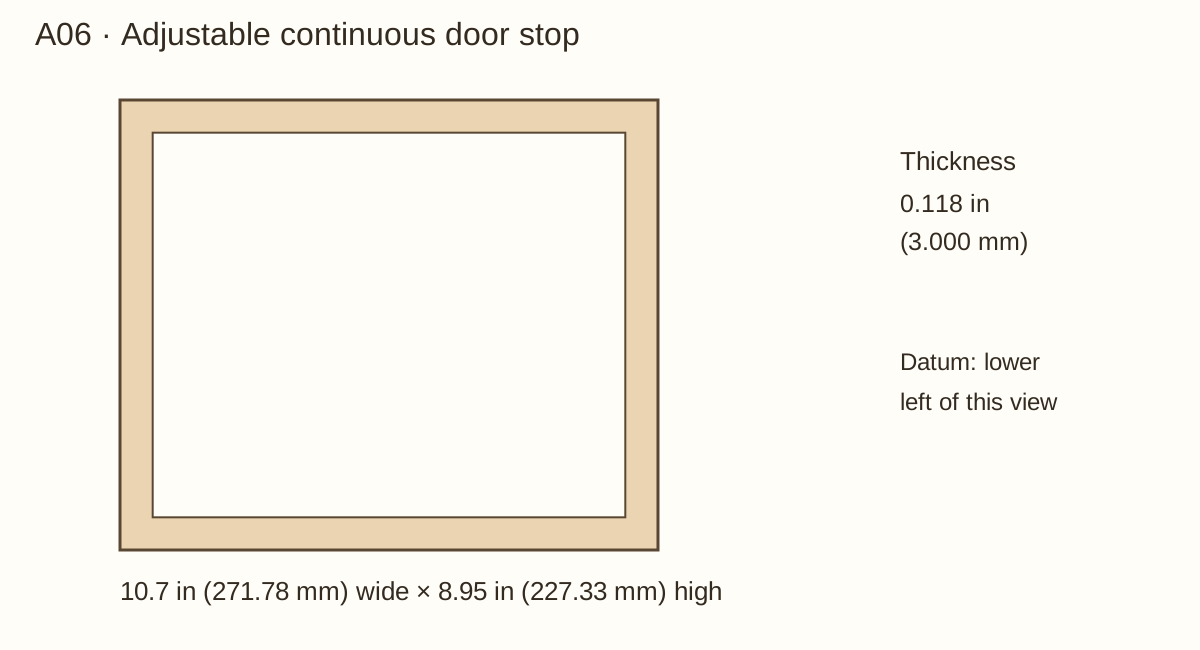
A06 · Adjustable continuous door stop acrylic
10.95 × 9.2 × 0.118 in (278.13 × 233.68 × 3 mm)
10.7 × 8.95 × 0.118 in (271.78 × 227.33 × 3 mm)
DCL1 · Door glazing keeper 1 acrylic
9.85 × 0.5 × 0.118 in (250.19 × 12.7 × 3 mm)
9.6 × 0.25 × 0.118 in (243.84 × 6.35 × 3 mm)
DCL2 · Door glazing keeper 2 acrylic
9.85 × 0.5 × 0.118 in (250.19 × 12.7 × 3 mm)
9.6 × 0.25 × 0.118 in (243.84 × 6.35 × 3 mm)
DCL3 · Door glazing keeper 3 acrylic
7.7 × 0.5 × 0.118 in (195.58 × 12.7 × 3 mm)
7.45 × 0.25 × 0.118 in (189.23 × 6.35 × 3 mm)
THE CREATURE CORNER · SP-SLIM-01 · REVIEW DESIGN
Part cuts · continued
Quantity one per ID. Long × short × thickness. G01 uses nominal free foam thickness, before compression; its backing is supplied separately by the converter. Rough blanks include 1/4-inch (6.35 mm) trim on both long/short dimensions; the final fit is from released stock, not the nominal label. Hole positions follow the part drawings.
Part / material
Rough blank
Finished reference
DCL4 · Door glazing keeper 4 acrylic
7.7 × 0.5 × 0.118 in (195.58 × 12.7 × 3 mm)
7.45 × 0.25 × 0.118 in (189.23 × 6.35 × 3 mm)
K1 · Roof pane keeper K1 acrylic
5.25 × 0.75 × 0.118 in (133.35 × 19.05 × 3 mm)
5 × 0.5 × 0.118 in (127 × 12.7 × 3 mm)
K2 · Roof pane keeper K2 acrylic
5.25 × 0.75 × 0.118 in (133.35 × 19.05 × 3 mm)
5 × 0.5 × 0.118 in (127 × 12.7 × 3 mm)
K3 · Roof pane keeper K3 acrylic
8.25 × 0.75 × 0.118 in (209.55 × 19.05 × 3 mm)
8 × 0.5 × 0.118 in (203.2 × 12.7 × 3 mm)
K4 · Roof pane keeper K4 acrylic
8.25 × 0.75 × 0.118 in (209.55 × 19.05 × 3 mm)
8 × 0.5 × 0.118 in (203.2 × 12.7 × 3 mm)
SP0 · Measured door-stop spacer DS0 hardwood
0.5 × 0.5 × 0.17 in (12.7 × 12.7 × 4.33 mm)
0.25 × 0.25 × 0.17 in (6.35 × 6.35 × 4.33 mm)
SP1 · Measured door-stop spacer DS1 hardwood
0.5 × 0.5 × 0.17 in (12.7 × 12.7 × 4.33 mm)
0.25 × 0.25 × 0.17 in (6.35 × 6.35 × 4.33 mm)
THE CREATURE CORNER · SP-SLIM-01 · REVIEW DESIGN
Part cuts · continued
Quantity one per ID. Long × short × thickness. G01 uses nominal free foam thickness, before compression; its backing is supplied separately by the converter. Rough blanks include 1/4-inch (6.35 mm) trim on both long/short dimensions; the final fit is from released stock, not the nominal label. Hole positions follow the part drawings.
Part / material
Rough blank
Finished reference
SP2 · Measured door-stop spacer DS2 hardwood
0.5 × 0.5 × 0.17 in (12.7 × 12.7 × 4.33 mm)
0.25 × 0.25 × 0.17 in (6.35 × 6.35 × 4.33 mm)
SP3 · Measured door-stop spacer DS3 hardwood
0.5 × 0.5 × 0.17 in (12.7 × 12.7 × 4.33 mm)
0.25 × 0.25 × 0.17 in (6.35 × 6.35 × 4.33 mm)
SP4 · Measured door-stop spacer DS4 hardwood
0.5 × 0.5 × 0.17 in (12.7 × 12.7 × 4.33 mm)
0.25 × 0.25 × 0.17 in (6.35 × 6.35 × 4.33 mm)
SP5 · Measured door-stop spacer DS5 hardwood
0.5 × 0.5 × 0.17 in (12.7 × 12.7 × 4.33 mm)
0.25 × 0.25 × 0.17 in (6.35 × 6.35 × 4.33 mm)
SP6 · Measured door-stop spacer DS6 hardwood
0.5 × 0.5 × 0.17 in (12.7 × 12.7 × 4.33 mm)
0.25 × 0.25 × 0.17 in (6.35 × 6.35 × 4.33 mm)
SP7 · Measured door-stop spacer DS7 hardwood
0.5 × 0.5 × 0.17 in (12.7 × 12.7 × 4.33 mm)
0.25 × 0.25 × 0.17 in (6.35 × 6.35 × 4.33 mm)
SP8 · Measured door-stop spacer DS8 hardwood
0.5 × 0.5 × 0.17 in (12.7 × 12.7 × 4.33 mm)
0.25 × 0.25 × 0.17 in (6.35 × 6.35 × 4.33 mm)
THE CREATURE CORNER · SP-SLIM-01 · REVIEW DESIGN
Part cuts · continued
Quantity one per ID. Long × short × thickness. G01 uses nominal free foam thickness, before compression; its backing is supplied separately by the converter. Rough blanks include 1/4-inch (6.35 mm) trim on both long/short dimensions; the final fit is from released stock, not the nominal label. Hole positions follow the part drawings.
Part / material
Rough blank
Finished reference
SP9 · Measured door-stop spacer DS9 hardwood
0.5 × 0.5 × 0.17 in (12.7 × 12.7 × 4.33 mm)
0.25 × 0.25 × 0.17 in (6.35 × 6.35 × 4.33 mm)
THE CREATURE CORNER · SP-SLIM-01 · REVIEW DESIGN
Veneer allocation and grain
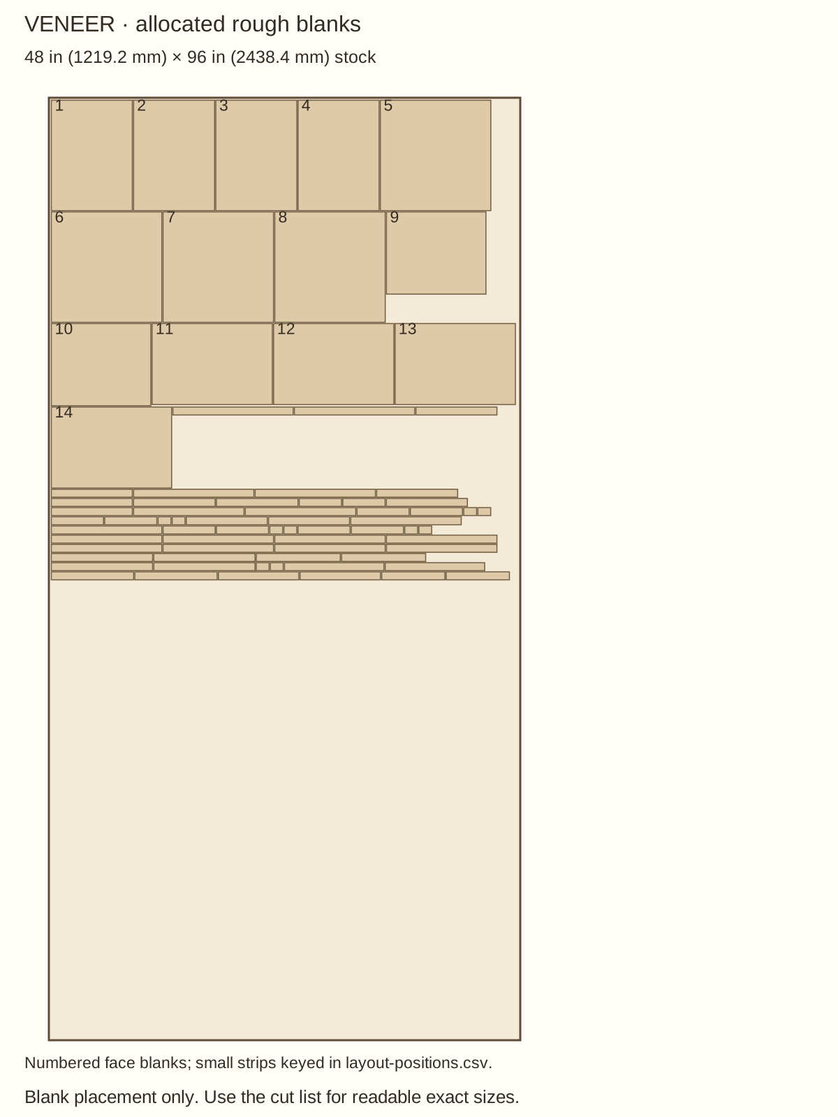
The specification contains 74 separate face, edge and reveal blanks allocated on one sheet. Opposing face blanks balance the core; they do not replace bare structural glue lands.
Family
Cut rule
Face blanks
Each panel has two; core face dimension plus 0.31 in (7.874 mm) in each direction for outer allowance and trim.
Outer edge strips
Four per panel; core length plus 0.31 in (7.874 mm), strip width core thickness plus 0.31 in.
Opening reveals
Two pairs per opening; lengths from the core opening plus 1/4 in (6.35 mm), width core thickness plus 0.31 in.
Grain
Roof/floor run along the declared grain axis; walls and door uprights vertical; long narrow edges/reveals along their length.
Exact allocation
See downloads/veneer-cuts.csv and the specification for every named blank and orientation.
Trim after the actual finished stack is known. The 0.030-inch (0.762 mm) model skin represents veneer, adhesive and finish together. Maple and walnut previews do not release substitute material thicknesses.
Cutting diagrams
THE CREATURE CORNER · SP-SLIM-01 · REVIEW DESIGN
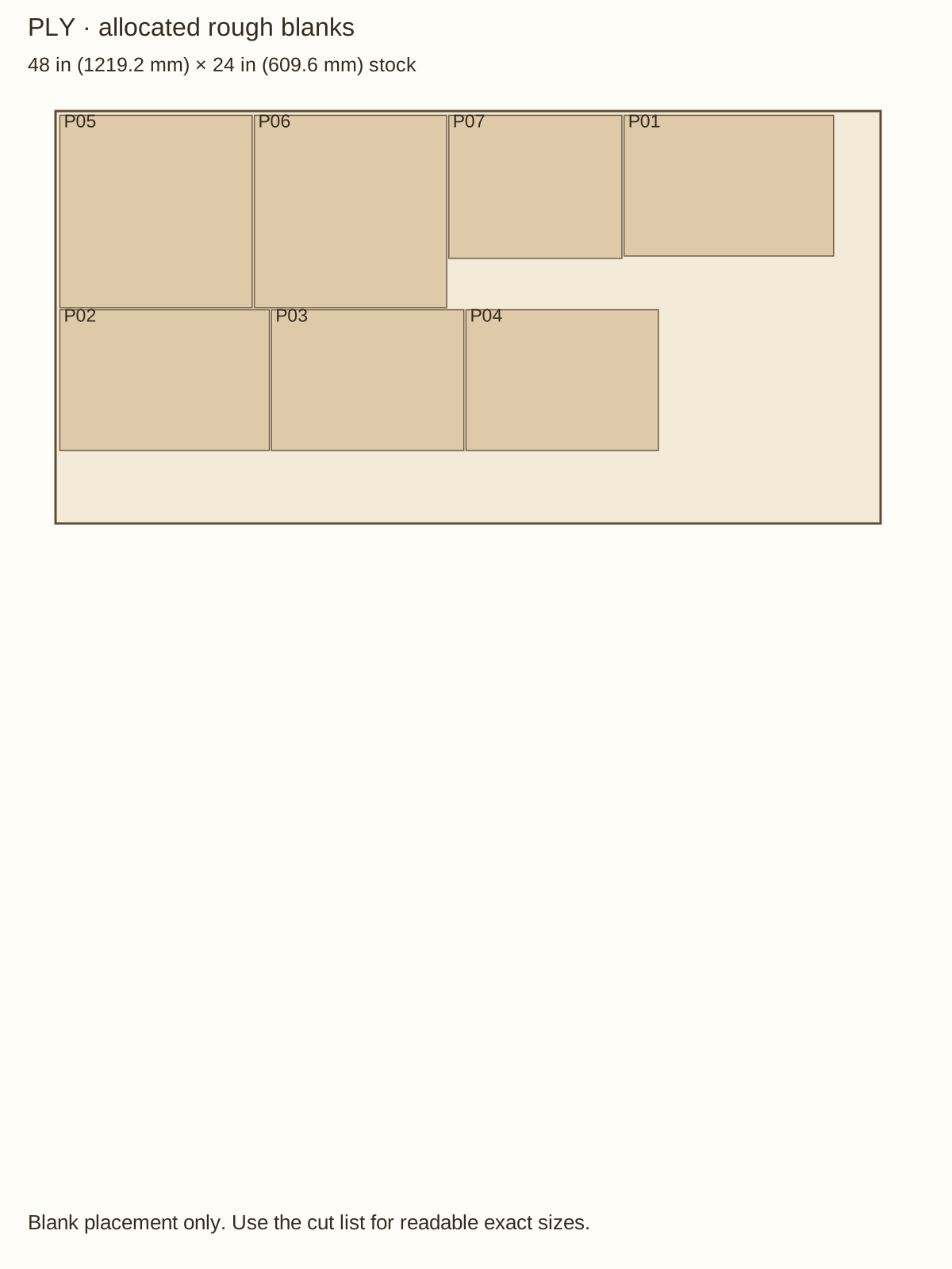
PLY stock allocation
Separate rough blanks; allow trim, kerf and trial stock · Select to enlarge
Do not read cut dimensions from this scaled picture. Use the cut list and downloadable layout/specification. Veneer strips are identified in the veneer schedule.
THE CREATURE CORNER · SP-SLIM-01 · REVIEW DESIGN
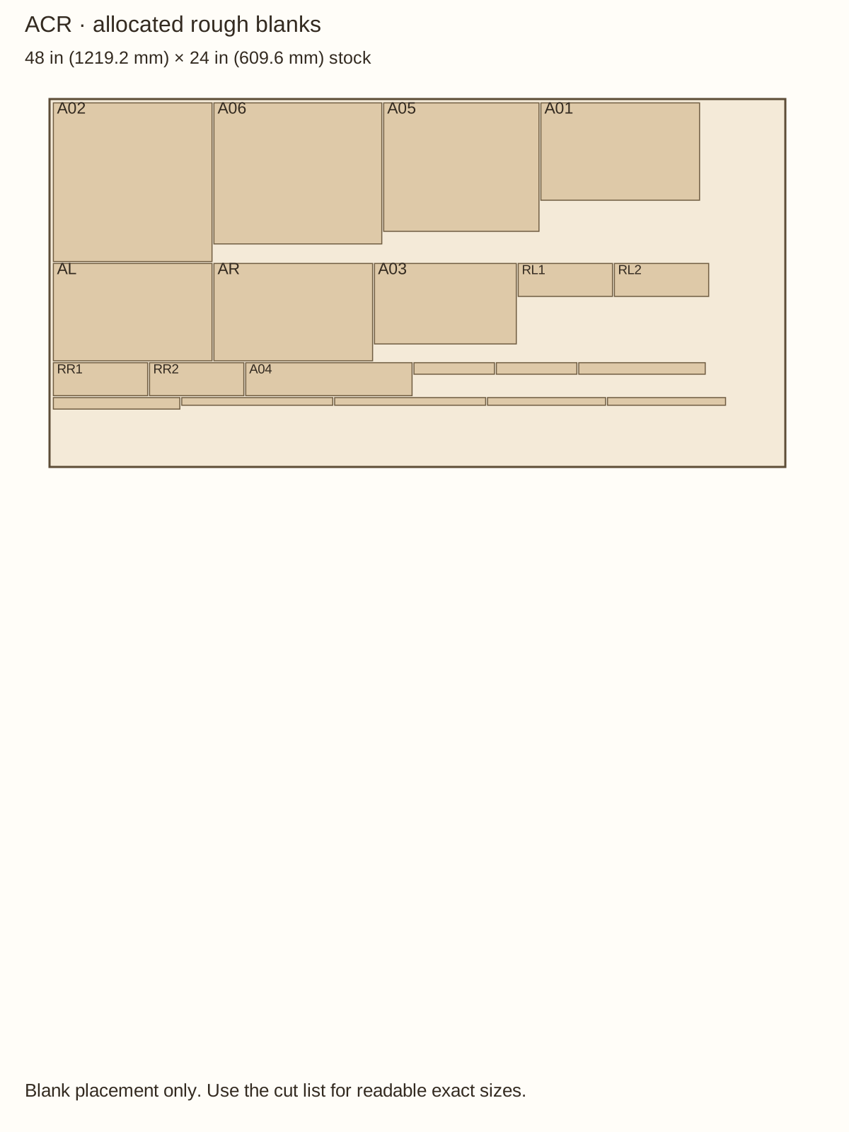
ACR stock allocation
Separate rough blanks; allow trim, kerf and trial stock · Select to enlarge
Do not read cut dimensions from this scaled picture. Use the cut list and downloadable layout/specification. Veneer strips are identified in the veneer schedule.
THE CREATURE CORNER · SP-SLIM-01 · REVIEW DESIGN
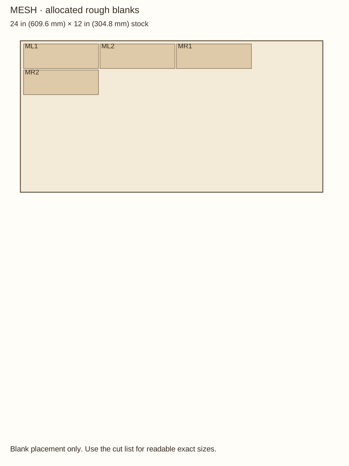
MESH stock allocation
Separate rough blanks; allow trim, kerf and trial stock · Select to enlarge
Do not read cut dimensions from this scaled picture. Use the cut list and downloadable layout/specification. Veneer strips are identified in the veneer schedule.
THE CREATURE CORNER · SP-SLIM-01 · REVIEW DESIGN
VENEER stock allocation
Separate rough blanks; allow trim, kerf and trial stock · Select to enlarge
Do not read cut dimensions from this scaled picture. Use the cut list and downloadable layout/specification. Veneer strips are identified in the veneer schedule.
THE CREATURE CORNER · SP-SLIM-01 · REVIEW DESIGN
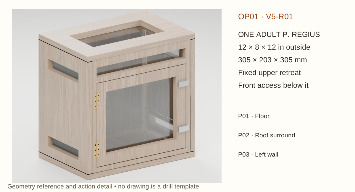
OP01 · Confirm the animal and the space
Parts: P01 Floor; P02 Roof surround; P03 Left wall; P04 Right wall; P05 Back; P06 Fixed front; P07 Door frame
Tools ready: Tape measure; this guide; current species care guide
Before you begin: This candidate is for one adult regal jumping spider. Do not use it for spiderlings, juveniles or unexpected offspring.
Confirm the animal and the space · Select to enlarge
Confirm the spider is an adult Phidippus regius and plan a separate secure holding enclosure for cleaning or repairs. A previously mated female may produce young; the adult enclosure is not approved to contain them.
Measure a level, full-base support and leave at least 12 inches (305 mm) clear in front for the door and your hand. Keep the case out of direct sun and away from pets, children and heat sources.
Compare the usable box of 9.8 × 6 × 9.75 inches (249 × 152 × 248 mm), above the floor layer, with the animal’s needs. Furnishings will occupy some of it.
Check before continuing: Adult identity, accessible location and a holding enclosure recorded. Preferred 8 × 8 × 12-inch usable space is not met.
Wait / hold: H01–H07 must close before animal use.
THE CREATURE CORNER · SP-SLIM-01 · REVIEW DESIGN
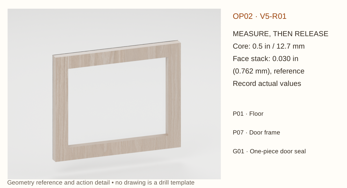
OP02 · Receive and measure the materials
Parts: P01 Floor; P07 Door frame; G01 One-piece door seal; A05 Door glazing and seal face; ML1 Fine mesh L1
Before you begin: Do not cut the production parts from nominal stock labels.
Receive and measure the materials · Select to enlarge
Measure plywood thickness at several points. The reference core is 1/2 inch (12.7 mm); inspect for voids, delamination and twist. Record the actual range.
Make a balanced veneer sample with the exact preseal, PSA veneer and finish. Each complete face stack targets 0.030 inch (0.762 mm). Measure after full cure; recalculate the specification if it differs.
Measure the acrylic and silicone ring. Check the mesh certificate, wire condition and maximum aperture under magnification. Photograph received product labels.
Check before continuing: All receiving fields filled with actual values, or explicitly held. No guessed thickness is entered.
Wait / hold: Complete full-cure and compatibility trials before releasing cuts.
THE CREATURE CORNER · SP-SLIM-01 · REVIEW DESIGN
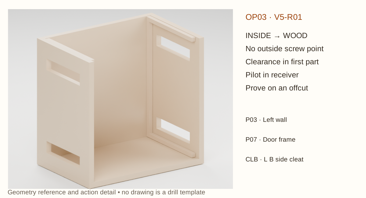
OP03 · Prove the material and screw combinations
Parts: P03 Left wall; P07 Door frame; CLB L B side cleat
Before you begin: A screw pilot is a small starting hole in the receiving wood. Its diameter comes from a successful trial, not the picture.
Prove the material and screw combinations · Select to enlarge
Use matching offcuts for each screw length and material stack in the station schedule. Drill clearance through the first member so the screw can pull the joint together; drill a smaller trial pilot in the receiving wood.
Fit depth stops, seat each head, then cut one sample apart. Check penetration and retained outside wood; reject splitting, stripped threads, cracks in acrylic or a protruding point.
Test ASI 509 adhesion on the exact acrylic, stainless mesh and finished wood. Test PSA bond and balanced-panel flatness through representative dry/humid room cycles.
Check before continuing: Record passing pilot/depth/head details and material compatibility. Failed trials require a specification change.
Wait / hold: ASI strength/adhesion trial: at least 7 days; confinement or unsuitable conditions can require longer. Finish full cure remains a supplier hold.
THE CREATURE CORNER · SP-SLIM-01 · REVIEW DESIGN
OP04 · Allocate stock and mark the parts
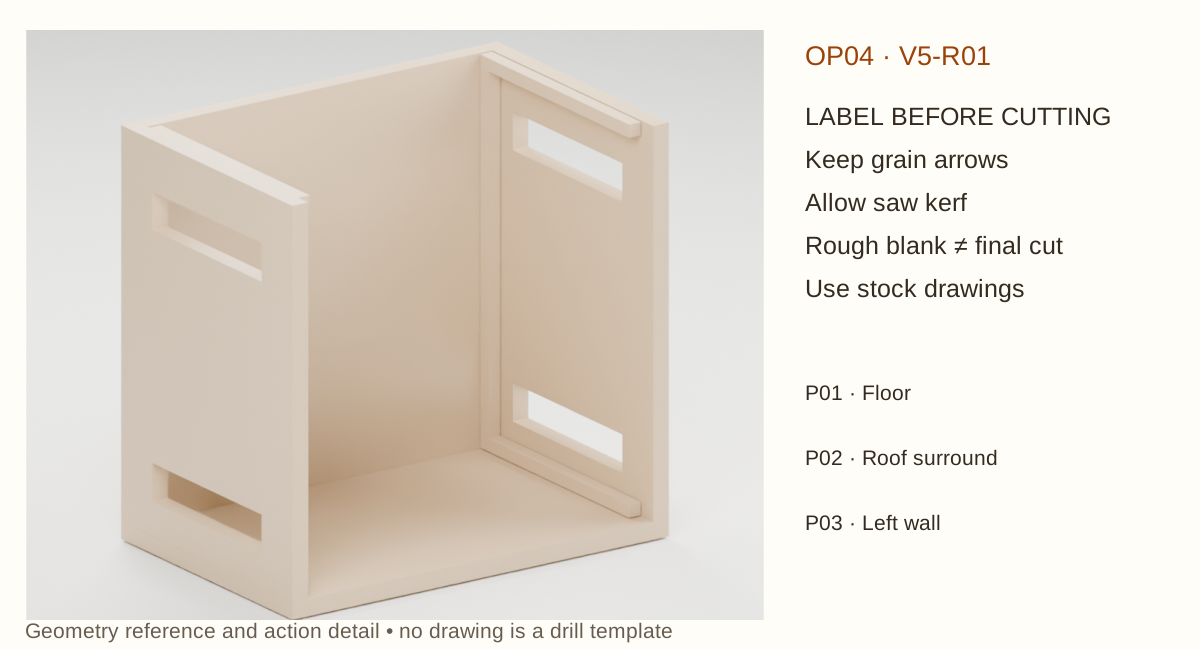
Parts: P01 Floor; P02 Roof surround; P03 Left wall; P04 Right wall; P05 Back; P06 Fixed front; P07 Door frame
Before you begin: The layout includes trimming and a 1/8-inch (3.175 mm) saw kerf, the material removed by the blade.
Allocate stock and mark the parts · Select to enlarge
Mark all rough blanks using the numbered stock drawings. Keep the indicated grain direction; reserve offcuts for trials and the door-stop spacers.
Label the inside face, front edge and bottom edge of each part before separating it. P01 is the floor; P02 is the roof; P03/P04 are left/right; P05 is back; P06 is fixed front; P07 is the door.
Support the sheet on both sides of the cut and use the saw’s guards and extraction. Cut oversize blanks, then square and trim to the released finished dimensions.
Check before continuing: Every part has its ID and datum edges. Stock defects have not consumed an essential part or trial blank.
Wait / hold: Stop if actual stock does not match H01.
Before you begin: Clamp the panel flat with sacrificial backing. Never plunge a cutter into a freehand outline.
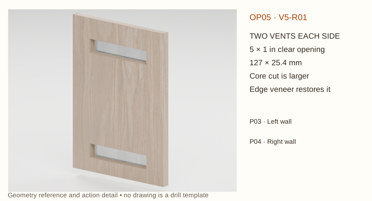
Machine the four side vents · Select to enlarge
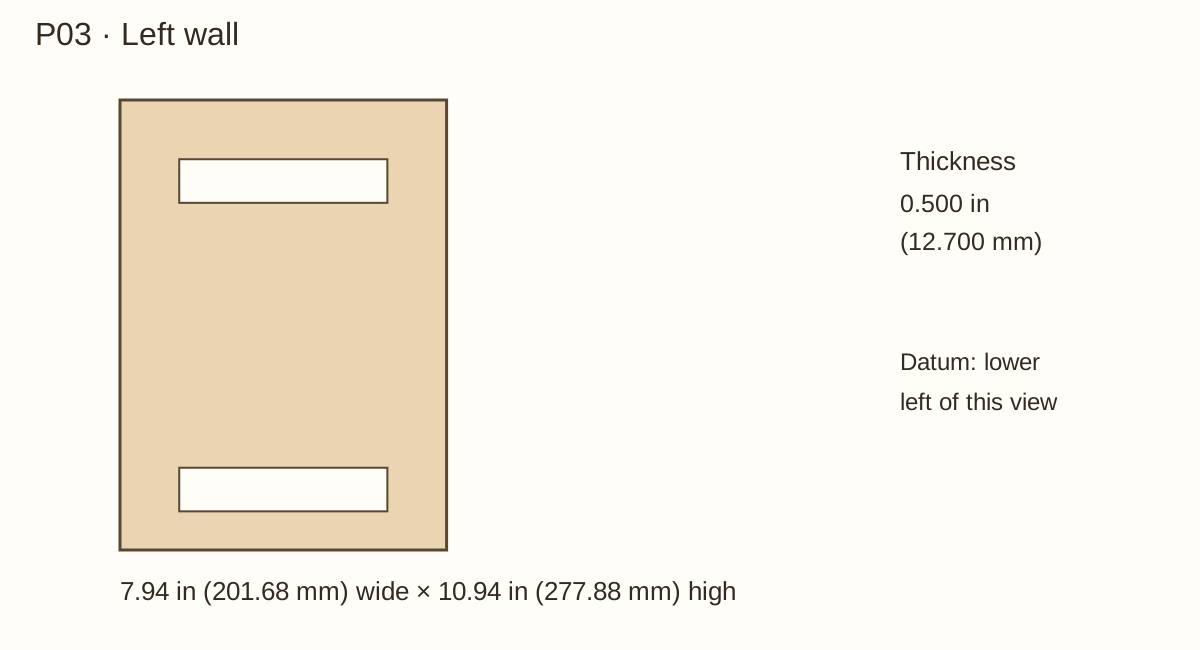
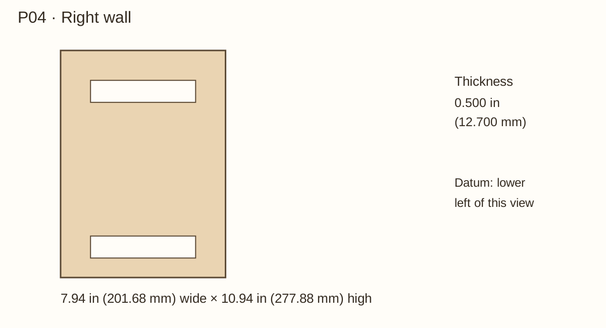
Use the part drawing to locate both openings on each wall from its front and bottom datums. Finished openings are 5 × 1 inches (127 × 25.4 mm). Their global heights are 1.5–2.5 and 9–10 inches (38.1–63.5 and 228.6–254 mm).
The core opening includes an edge-veneer allowance. Use the core bounds in the drawing, not the finished aperture dimensions, for machining.
Cut a trial first; machine the openings, remove splinters and retain the flat reference faces. Apply the same operation to the opposite wall.
Check before continuing: The two walls match; all four finished apertures will remain clear after edge strips. No void or split runs into a retainer screw land.
Wait / hold: Do not install mesh during dusty machining.
THE CREATURE CORNER · SP-SLIM-01 · REVIEW DESIGN
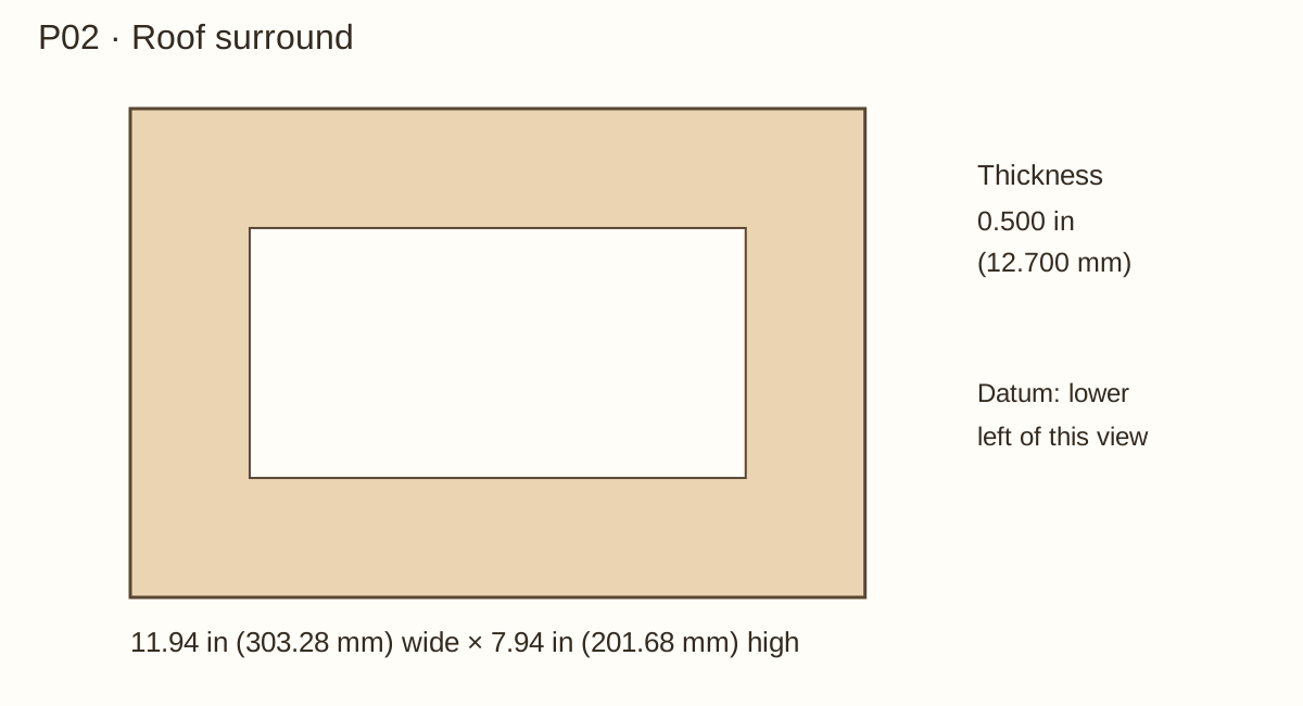
OP06 · Cut the roof window and fixed front openings
Parts: P02 Roof surround; P06 Fixed front
Tools ready: Released drawings; router template; clamps; sacrificial backing
Before you begin: The narrow fixed transom rail must stay intact. Do not copy the door opening into the roof.
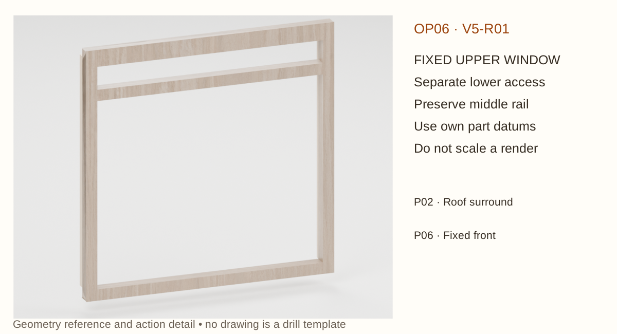
Cut the roof window and fixed front openings · Select to enlarge
Machine P02 for an 8 × 4-inch (203.2 × 101.6 mm) finished roof opening, centred in the roof.
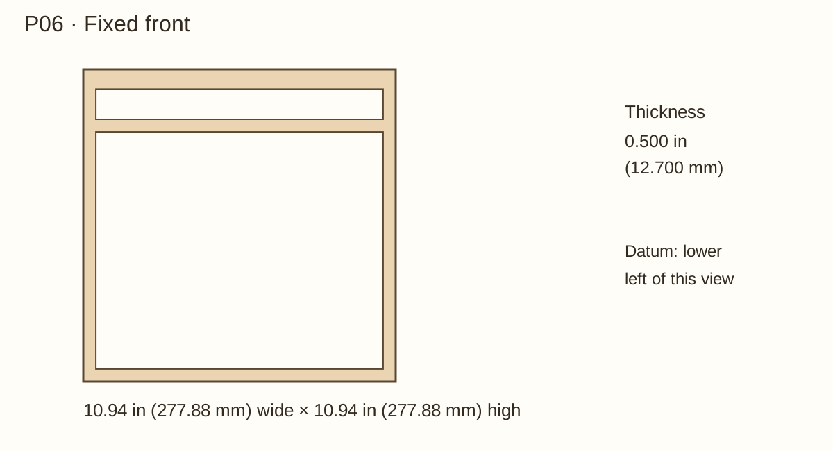
Machine P06 for the 10 × 8.25-inch (254 × 209.55 mm) finished lower opening and the 10 × 1-inch (254 × 25.4 mm) fixed transom. Use the separate core-cut bounds for veneer allowance.
Dry-position the fixed front and roof on the shell. Check that the front transom stays above the routine door access and that all lands remain flat.
Check before continuing: Both parts match their own drawings. The transom rail is sound and the roof opening has no sharp exposed plywood edge.
Wait / hold: Keep these panels loose for later inside access.
THE CREATURE CORNER · SP-SLIM-01 · REVIEW DESIGN
OP07 · Make the door frame
Parts: P07 Door frame; A05 Door glazing and seal face
Before you begin: The finished reveal is 0.060 inch (1.524 mm) per side. It is not an open containment allowance.
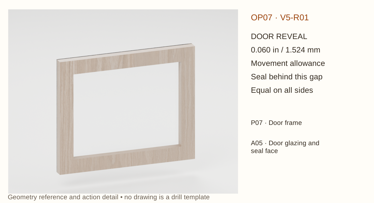
Make the door frame · Select to enlarge
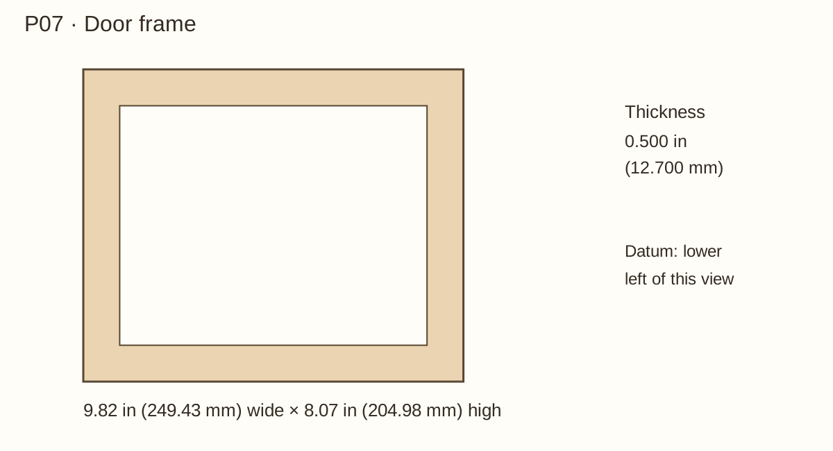
Trim the released P07 core blank. Machine the clear window with its veneer allowance. The finished frame outside is 9.88 × 8.13 inches (250.95 × 206.50 mm).
Keep the frame flat while fitting the opening; check it on a flat surface in both orientations. Leave the complete outer back land for the acrylic seal face.
Place the unfinished frame in P06 using equal reference spacers. Check the proposed hinge and latch lands before any irreversible hole.
Check before continuing: A straight, undamaged frame fits the opening with equal planned reveal. Hinge mortises and catch positions remain uncut until received fittings are available.
Wait / hold: Do not glue a warped door into submission.
THE CREATURE CORNER · SP-SLIM-01 · REVIEW DESIGN
OP08 · Prepare the cleats and bare glue lands
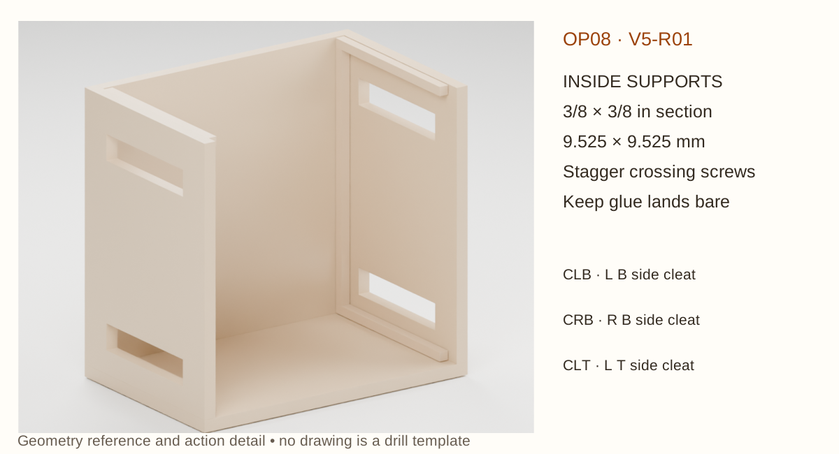
Parts: CLB L B side cleat; CRB R B side cleat; CLT L T side cleat; CRT R T side cleat; CLF L F corner cleat; CRF R F corner cleat; CLK L K corner cleat; CRK R K corner cleat
Before you begin: Machine small cleats from larger supported stock. Do not hold a tiny blank beside a blade.
Prepare the cleats and bare glue lands · Select to enlarge
Prepare the eight 3/8 × 3/8-inch (9.525 × 9.525 mm) cleats. Side horizontal lengths are 6.88 inches (174.75 mm); front/back vertical lengths are 10.13 inches (257.30 mm).
Mark their inside positions on P03/P04. Leave clean bare wood at structural glue lands; PSA veneer or a coating cannot become the glue joint.
Lay out the CS, CV, CB and CF station groups from the machining schedule. The perpendicular screws are deliberately staggered; do not align them at one corner.
Check before continuing: Cleats fit without pushing the panels out of square. Every screw has a receiver and a clear path.
Wait / hold: No glue until dry-fit checks pass.
THE CREATURE CORNER · SP-SLIM-01 · REVIEW DESIGN
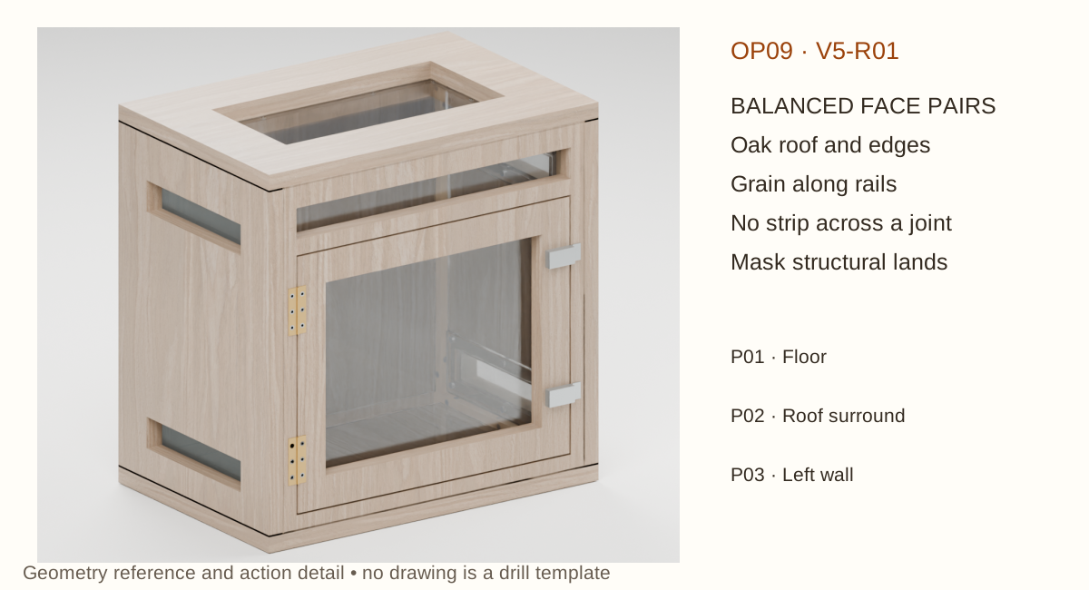
OP09 · Apply balanced veneer and cover the edges
Parts: P01 Floor; P02 Roof surround; P03 Left wall; P04 Right wall; P05 Back; P06 Fixed front; P07 Door frame
Before you begin: Keep veneer out of bare structural glue lands. Never bridge a door gap or case joint with one strip.
Apply balanced veneer and cover the edges · Select to enlarge
Prepare the exact approved preseal system, leaving masked glue lands bare. Follow the veneer supplier’s preparation method and the finish label.
Apply paired face veneers to balance each panel. Use firm scraper pressure from the centre along the grain; trim with multiple controlled knife passes and a backing board.
Apply matching strips to exposed panel edges and all window/vent reveals. Grain runs along long rails and vertically on uprights. Trim flush without rounding away the planned door clearance.
Check before continuing: Roof, outside faces and visible edges are uniformly covered; no raw plywood stripe, bubble, lifted edge or unbalanced door remains.
Wait / hold: At least 24 hours after preseal under the veneer instructions, and any longer full-cure interval required for the actual finish/adhesive combination.
THE CREATURE CORNER · SP-SLIM-01 · REVIEW DESIGN
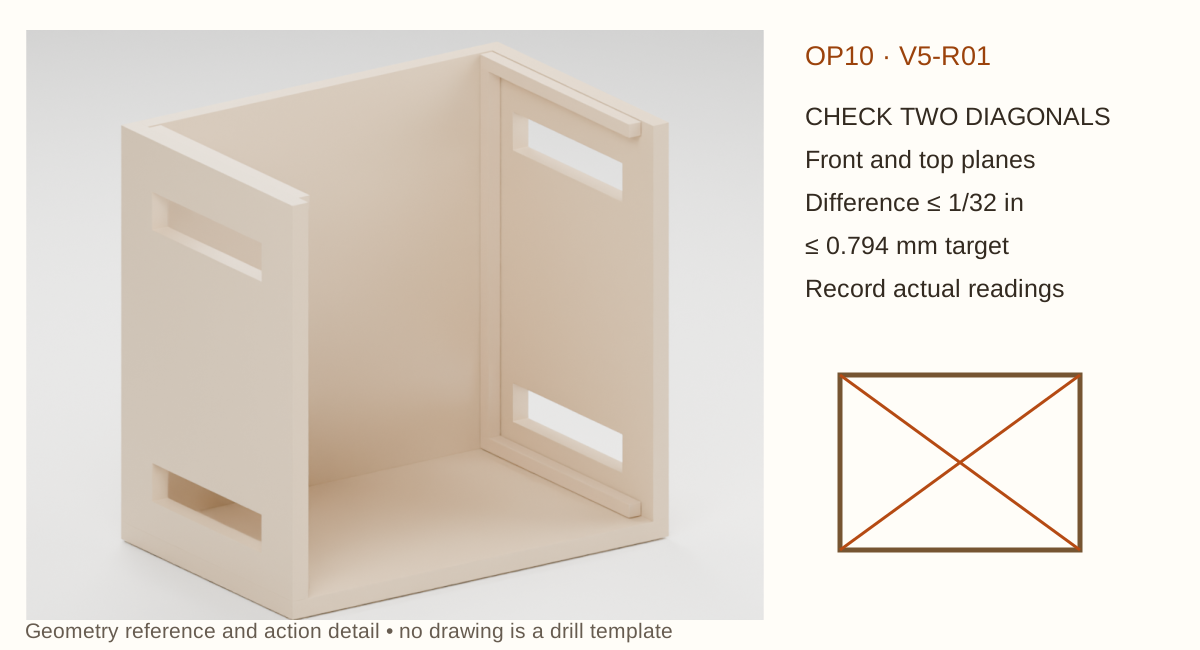
OP10 · Clamp and check the bare shell
Parts: P01 Floor; P03 Left wall; P04 Right wall; P05 Back; CLB L B side cleat; CRB R B side cleat; CLK L K corner cleat; CRK R K corner cleat
Before you begin: Support every panel; clamps must not crush a finished veneer edge.
Clamp and check the bare shell · Select to enlarge
Dry-assemble the floor, sides and back with the internal cleats, keeping the fixed front and roof removable. Match the marked front and bottom edges.
Compare both front-opening diagonals and both top diagonals. This design target is no more than 1/32 inch (0.794 mm) difference; record the actual readings.
Check for rocking, steps at corners and daylight at mating joints. Correct the fit before bonding rather than using screws to force twisted panels together.
Check before continuing: Joint faces meet, dimensions match the released drawing and both diagonal differences meet the design target.
Wait / hold: Dry fit only.
THE CREATURE CORNER · SP-SLIM-01 · REVIEW DESIGN
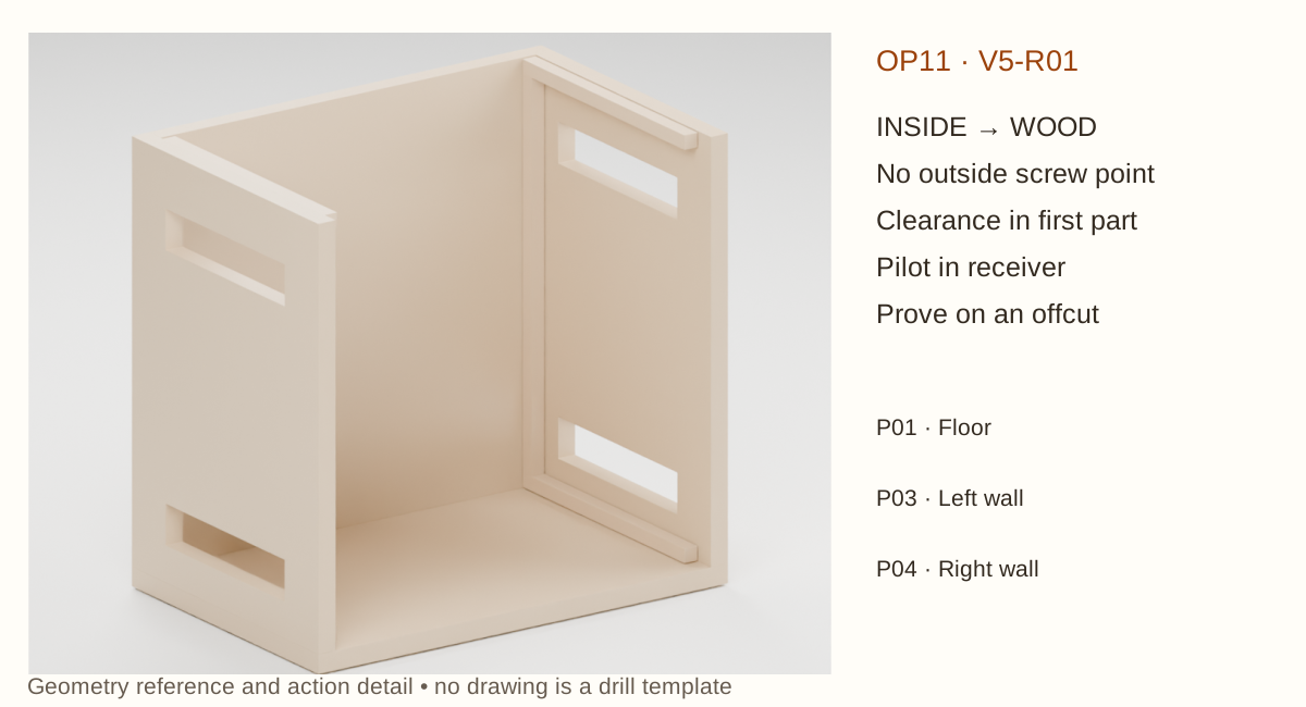
OP11 · Bond and fasten the shell
Parts: P01 Floor; P03 Left wall; P04 Right wall; P05 Back; CLB L B side cleat; CRB R B side cleat; CLK L K corner cleat; CRK R K corner cleat
Before you begin: Finish is not a structural glue surface. Keep glue away from pane pockets and ventilation openings.
Bond and fasten the shell · Select to enlarge
Apply the selected wood glue to clean bare mating lands within its labelled open/assembly time. Reassemble, clamp and recheck diagonals before the glue sets.
Install the scheduled internal #4 × 3/4-inch (19.05 mm) screws with the proven pilot and depth stop. These pass through 3/8-inch (9.525 mm) cleats into panel faces.
Seat heads without stripping. Remove squeeze-out without flooding the wood; verify no screw point reaches the outside veneer.
Check before continuing: The shell remains square. Screws pull joints together without splitting or breaking through the exterior.
Wait / hold: Unstressed joints: clamp at least 30–60 minutes under suitable conditions; do not stress them for at least 24 hours. Follow longer product requirements.
THE CREATURE CORNER · SP-SLIM-01 · REVIEW DESIGN
OP12 · Dry-fit the inside panels and retainers
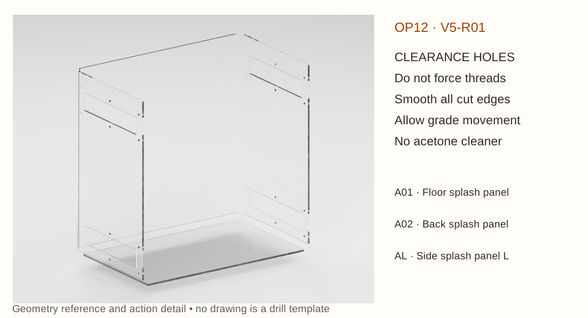
Parts: A01 Floor splash panel; A02 Back splash panel; AL Side splash panel L; AR Side splash panel R; A03 Fixed roof pane; A04 Fixed transom pane; A05 Door glazing and seal face; A06 Adjustable continuous door stop; RL1 Vent retaining ring L1; RL2 Vent retaining ring L2; RR1 Vent retaining ring R1; RR2 Vent retaining ring R2
Before you begin: Acrylic clearance holes must not grip screw threads. Avoid acetone and unsupported drilling.
Dry-fit the inside panels and retainers · Select to enlarge
Order or cut the acrylic parts from the released cut list with protected faces and smooth edges. Transfer vent openings from the finished walls onto the side splash panels.
Fit the roof pane, transom and door pane with their stated overlap. Check the stop ring against the door opening, keeping its inner opening unobstructed.
Dry-fit all keepers and screw holes with the actual clearance allowance proven in the coupon. Leave room for the actual grade’s movement; do not rigidly pinch or solvent-bond it to wood.
Check before continuing: No acrylic edge is chipped or loaded against a hard corner. Each retainer can be reached by a screwdriver during its planned assembly step.
Wait / hold: Remove parts for final wood finishing.
THE CREATURE CORNER · SP-SLIM-01 · REVIEW DESIGN
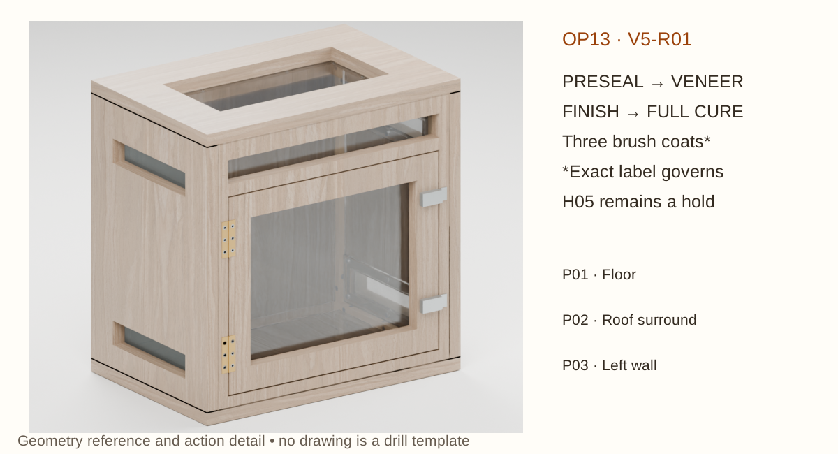
OP13 · Finish and fully cure the wood
Parts: P01 Floor; P02 Roof surround; P03 Left wall; P04 Right wall; P05 Back; P06 Fixed front; P07 Door frame
Tools ready: Selected brush-on finish; brush; ventilation; temperature/RH record
Before you begin: The exact finish SKU, compatibility and full-cure interval remain H05. Do not treat touch-dry as ready for an animal.
Finish and fully cure the wood · Select to enlarge
Coat exposed interior wood, cleats, exterior veneer and machined reveals using the approved system. Preserve masked structural glue lands that will still be joined.
The shortlisted brush-on Varathane system calls for three coats and a two-hour recoat interval under its stated conditions. Verify the received label before use.
Record each coat and conditions. Check edge coverage, brush drips on seal lands and any distortion of the door. Fully cure before installing the tested adhesive/seal assemblies.
Check before continuing: Smooth sealed surfaces; no blocked vent, sticky area or warped panel. The documented exact-product full-cure time has elapsed.
Wait / hold: H05 is a STOP until the exact product full-cure requirement is obtained and satisfied. Odour alone is not a cure test.
THE CREATURE CORNER · SP-SLIM-01 · REVIEW DESIGN
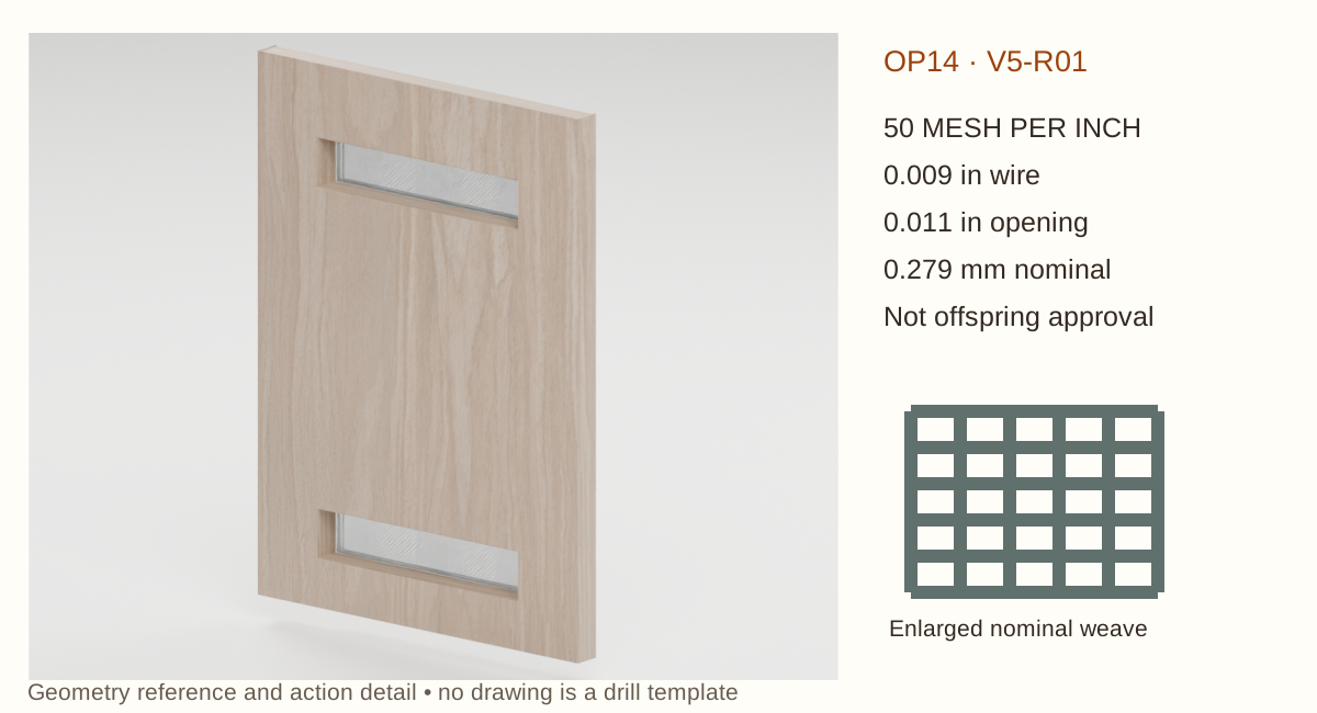
OP14 · Cut and inspect the fine mesh
Parts: ML1 Fine mesh L1; ML2 Fine mesh L2; MR1 Fine mesh R1; MR2 Fine mesh R2
Tools ready: Gloves; metal shears; magnifier; ruler; sealed scrap container
Before you begin: Cut wire ends are sharp. Keep every scrap away from the enclosure and the animal.
Cut and inspect the fine mesh · Select to enlarge
Cut four mesh blanks to 5.7 × 1.7 inches (144.78 × 43.18 mm). Maintain straight undamaged margins around each opening.
Inspect the full sheet against light and under magnification. Nominal 50 mesh uses 0.009-inch (0.229 mm) wire with 0.011-inch (0.279 mm) clear openings.
Reject broken, displaced or enlarged openings. Check the maximum aperture against the received supplier certificate; do not call the material escape-proof from its mesh count.
Check before continuing: Four intact blanks, no sharp strand extending beyond its captured border and no unverified substitution.
Wait / hold: Containment approval remains H04/H06; no live escape experiment.
THE CREATURE CORNER · SP-SLIM-01 · REVIEW DESIGN
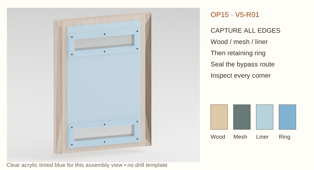
OP15 · Capture and seal the vent borders
Parts: ML1 Fine mesh L1; ML2 Fine mesh L2; MR1 Fine mesh R1; MR2 Fine mesh R2; AL Side splash panel L; AR Side splash panel R; RL1 Vent retaining ring L1; RL2 Vent retaining ring L2; RR1 Vent retaining ring R1; RR2 Vent retaining ring R2
Tools ready: ASI 509; proven screws/pilots; screwdriver; light; magnifier
Before you begin: The mesh must be mechanically captured all around. A loose edge behind a frame can bypass the fine openings.
Capture and seal the vent borders · Select to enlarge
On the inside wall, place each mesh blank over its opening, then the matching acrylic splash panel and the wider retaining ring. All cut wire edges stay behind the solid border.
Apply the tested thin continuous perimeter seal. Keep the viewing aperture open; do not smear silicone across the mesh.
Fit the VR screws in the stated staggered border pattern, tightening evenly by hand. Inspect corners and every edge with light and magnification before the front closes access.
Check before continuing: No lifted mesh edge, damaged strand or bypass channel. Keepers are flat, acrylic uncracked and screw points buried.
Wait / hold: Allow at least 7 days before sealant adhesion testing; extend for confined beads or label conditions.
THE CREATURE CORNER · SP-SLIM-01 · REVIEW DESIGN
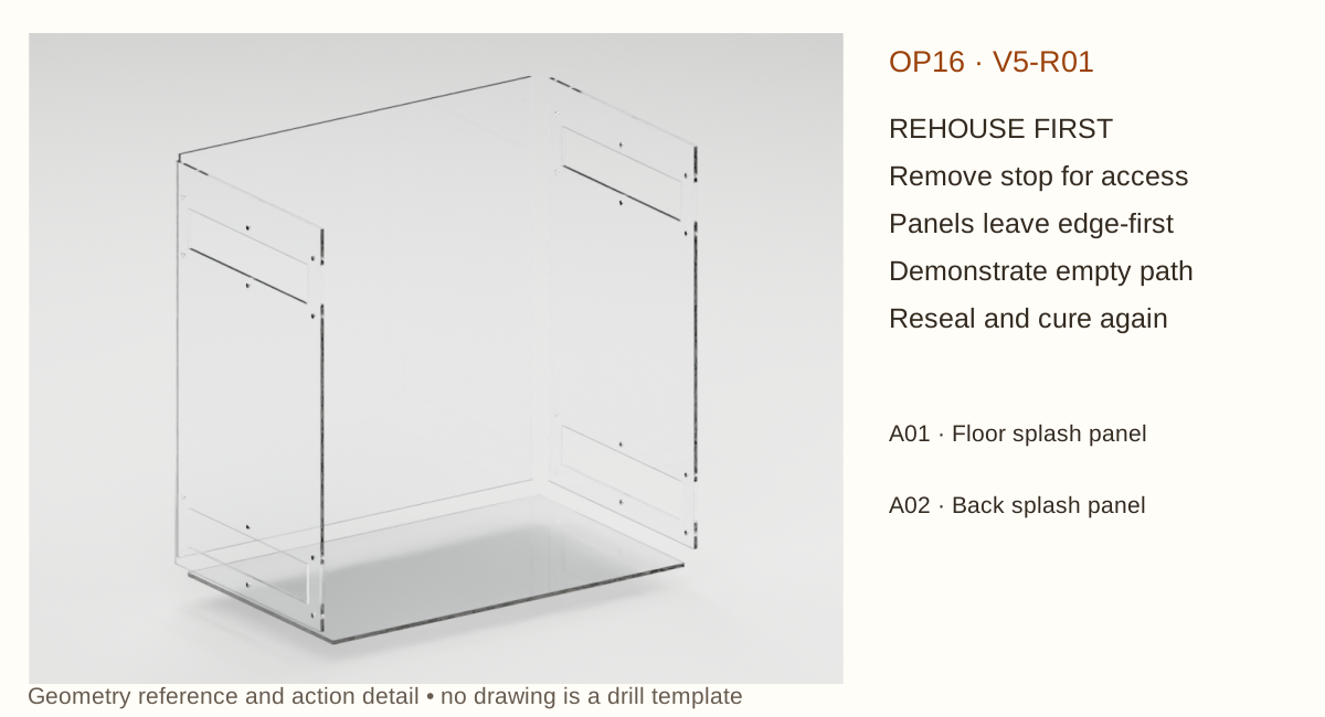
OP16 · Fit the floor and back splash panels
Parts: A01 Floor splash panel; A02 Back splash panel
Before you begin: These are cleaning/splash panels, not a waterproof tank. Do not fill the enclosure with water.
Fit the floor and back splash panels · Select to enlarge
Place the floor panel between the cleats and the back panel between the rear corner cleats. Smooth accessible edges and confirm the panels do not obstruct vents.
Use small tested positioning beads only where removal can later be reached. Close accessible dirt-trap seams with the tested nonstructural sealant detail.
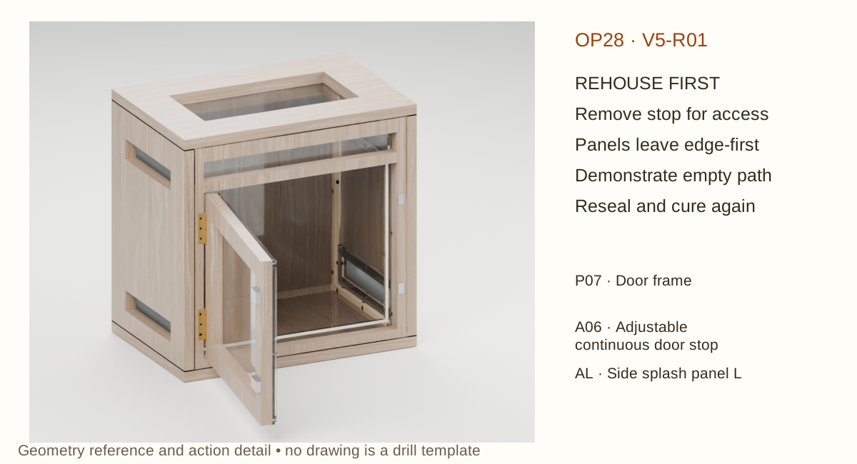
Record how each panel is lifted or removed through the open front. The wider back panel can leave edge-first only after the front stop is removed with the animal rehoused.
Check before continuing: No loose panel edge or exposed sharp corner. Service sequence is demonstrated in an empty prototype.
Wait / hold: Sealant cure as OP15; full removal/access remains H06.
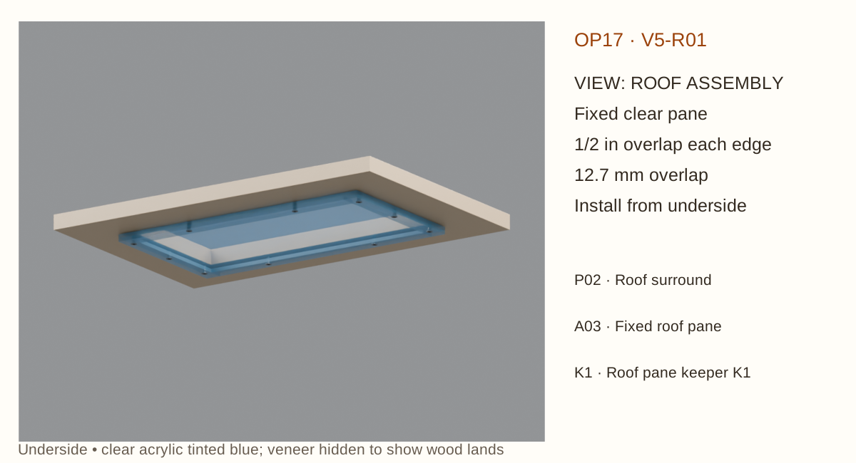
Before you begin: The roof stays fixed in routine use. Its pane is not a shelf and must carry no equipment or stacked enclosure.
Install the fixed roof glazing · Select to enlarge
Place P02 upside down on padded blocks. Centre A03 behind the roof opening, preserving its 1/2-inch (12.7 mm) overlap.
Apply the continuous tested perimeter bead, then the four keeper strips. Drill the released clearance pattern and install RK screws without bending the pane.
Check the entire seal and pane retention while the underside is still accessible. Remove sealant from the clear view only with a plastic-compatible method.
Check before continuing: Pane secure and perimeter continuous; no sharp edge, cracked acrylic or unsupported keeper.
Wait / hold: At least 7 days before adhesion test, longer if the actual bead is confined.
THE CREATURE CORNER · SP-SLIM-01 · REVIEW DESIGN
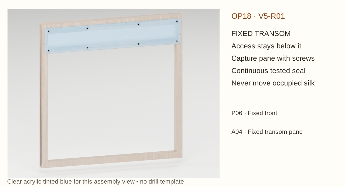
OP18 · Install the fixed front transom
Parts: P06 Fixed front; A04 Fixed transom pane
Tools ready: Padded bench; sealant; TG screws and washers
Before you begin: Keep the upper window fixed so routine door opening does not move the spider’s upper anchor area.
Install the fixed front transom · Select to enlarge
Place P06 face down on padding. Centre A04 behind the narrow upper opening and apply the tested perimeter bead.
Fit the TG clearance holes and retain the pane with the specified short screws and washers. Tighten by hand only enough to hold it flat.
Check the transom at every corner. Keep the lower opening and future gasket contact land free of silicone ridges.
Check before continuing: Fixed pane cannot shift out of its overlap; no through-gap or stressed hole.
Wait / hold: Sealant cure and adhesion check as OP15.
THE CREATURE CORNER · SP-SLIM-01 · REVIEW DESIGN
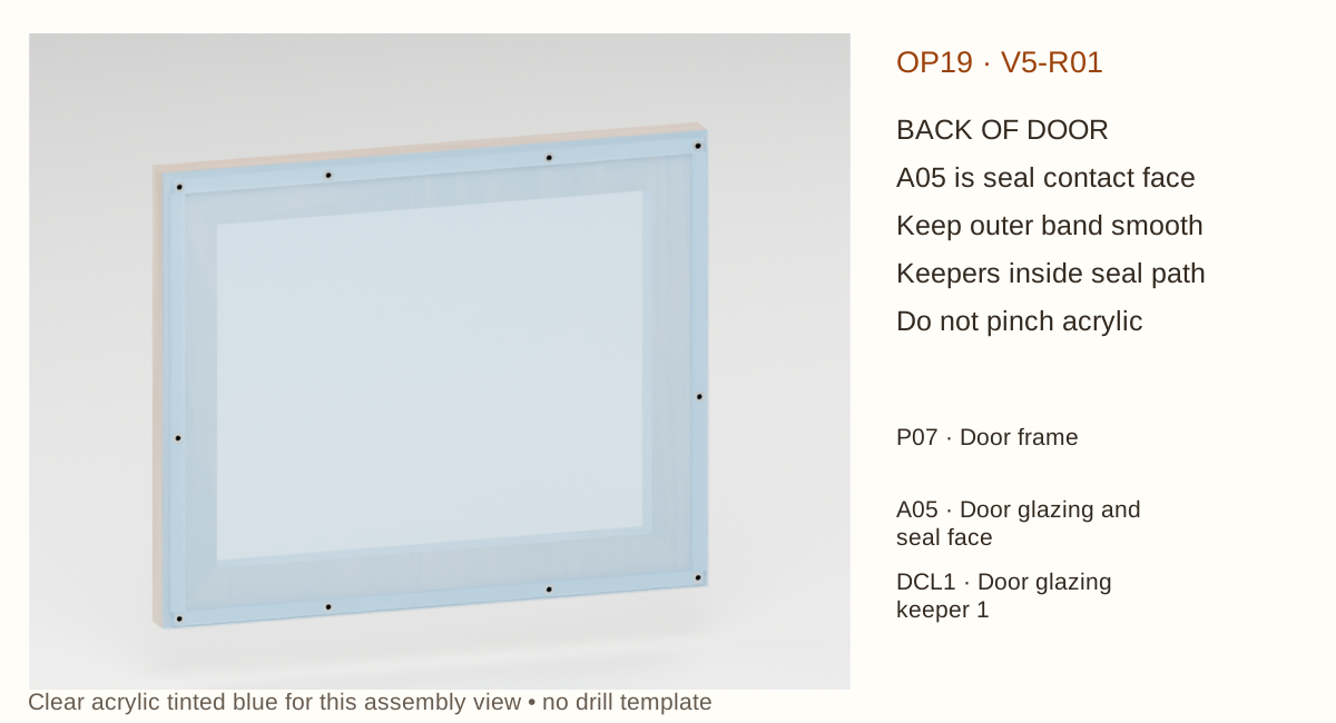
OP19 · Fit the door pane and keepers
Parts: P07 Door frame; A05 Door glazing and seal face; DCL1 Door glazing keeper 1; DCL2 Door glazing keeper 2; DCL3 Door glazing keeper 3; DCL4 Door glazing keeper 4
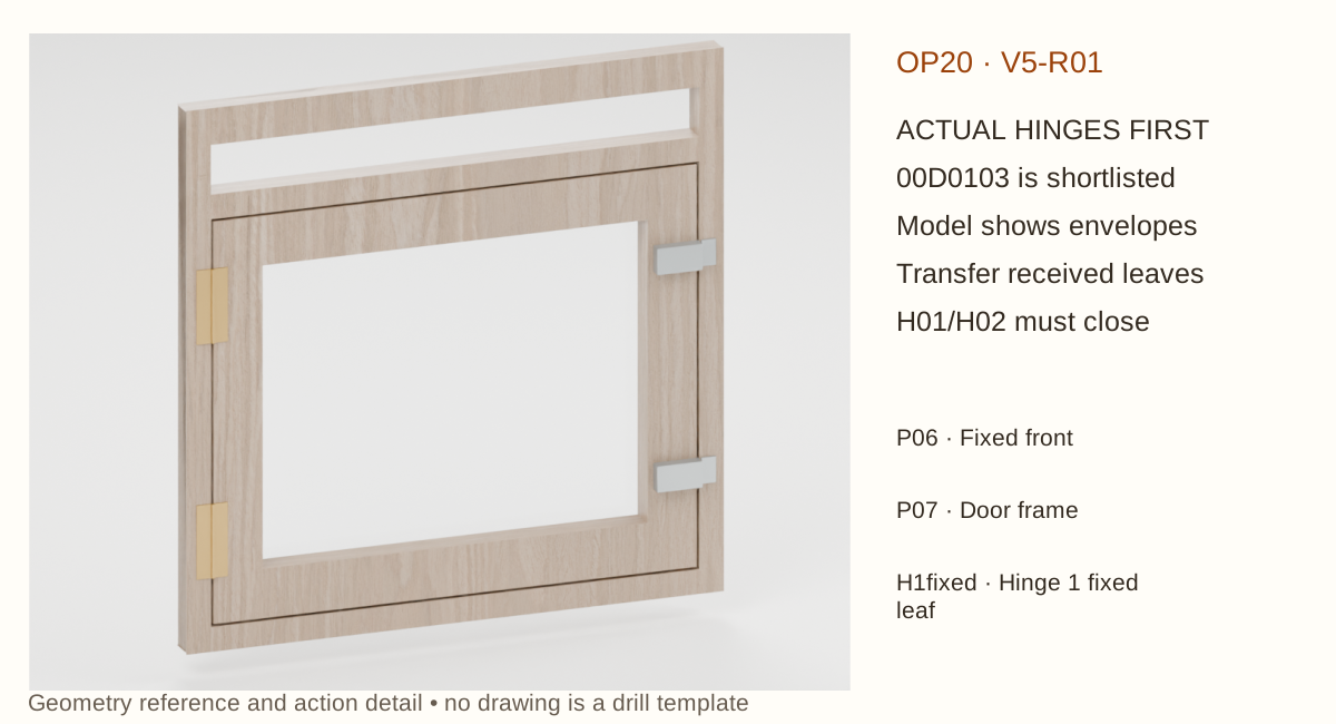
Before you begin: H02 is unresolved until actual hinge geometry is measured. The model’s hinge leaves are envelopes, not a drilling template.
Fit the actual hinges on the bench · Select to enlarge
With P06 flat on the bench, centre the completed door using 0.060-inch (1.524 mm) reveal spacers. Place hinge centres at 2.75 and 7.5 inches (69.85 and 190.5 mm) above the case bottom.
Use the received hinge leaves to transfer mortise depth, pin location and screw pattern. A mortise is the shallow pocket that lets the hinge sit at its designed level.
Trial the hinge and screw length on matching stock. Fit the two hinges and swing the supported door through at least 100 degrees without binding or pulling the frame sideways.
Check before continuing: Door moves smoothly, clears the fixed frame and stays aligned. Actual pin axis, screw purchase and service screwdriver access recorded.
Wait / hold: Do not continue on a merely approximate hinge fit.
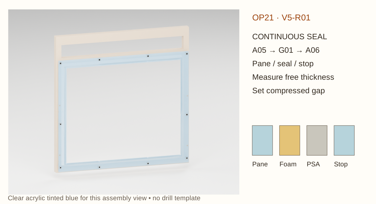
Before you begin: H03/H05: obtain the converter’s exact compatible adhesive backing, thickness and bond instructions first. Do not install a loose ring or cut a joint at a corner.
Set the continuous door seal · Select to enlarge
Measure foam and backing thickness separately around the perimeter. Target 75% of the free foam thickness plus the uncompressed backing. Bond the one-piece ring to A06 with its specified factory-applied backing; no adhesive edge may remain loose or exposed.
With the door closed and supported flat, fit the ten spacers so A06 supports G01 at that measured gap. Plane safely held oversize spacer stock, then cut individual spacers; seal and fully cure them.
Fit DS screws through clearance holes into P06. Close the door gently and use removable contact-transfer material to check an unbroken impression around the ring. Remove all test material afterward.
Check before continuing: Continuous contact without bending A06, distorting the door or excessively loading the hinges. Actual compression response still requires supplier/prototype confirmation.
Wait / hold: Hold H03 if any thin spot, gap or force problem remains.
THE CREATURE CORNER · SP-SLIM-01 · REVIEW DESIGN
OP22 · Fit two compact draw latches
Parts: P06 Fixed front; P07 Door frame; LB1 SCC25 body 1; LB2 SCC25 body 2; LC1 SCC25 counterplate 1; LC2 SCC25 counterplate 2
Tools ready: Two SCC25 latches; #4 trial screws; transfer marker; screwdriver
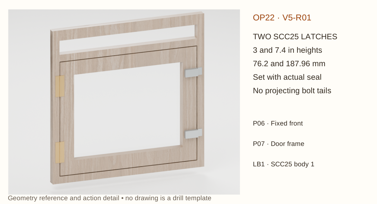
Before you begin: The manufacturer drawing is at zero clamping force. Drilling it blindly will not establish correct seal pressure.
Fit two compact draw latches · Select to enlarge
Set latch centre heights at 3 and 7.4 inches (76.2 and 187.96 mm). Hold each body on the door’s right stile and its counterplate on the fixed frame.
Close the actual latch against the measured seal setup. Transfer final holes from the actual fittings only after both latches close comfortably and the seal contact remains continuous.
Drill proven pilots with depth stops and fit the short countersunk screws. Check every point stays inside wood and every screw head sits within the hardware recess.
Check before continuing: Both latches positively engage; releasing one does not leave an unnoticed false-closed door. No exposed screw tail or oversized exterior bolt.
Wait / hold: Repeat H03 after final latch placement.
THE CREATURE CORNER · SP-SLIM-01 · REVIEW DESIGN
OP23 · Close the shell in the planned order
Parts: P02 Roof surround; P06 Fixed front; CLF L F corner cleat; CRF R F corner cleat; CLT L T side cleat; CRT R T side cleat
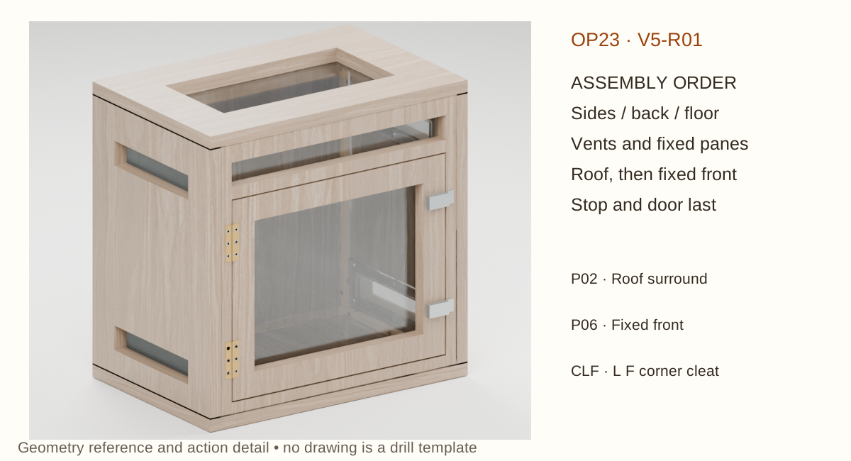
Before you begin: Finish all inaccessible mesh and glazing work before closing the front. Remove the hinged door temporarily if needed to protect it.
Close the shell in the planned order · Select to enlarge
Dry-fit the roof and fixed front again. Verify that the front-facing internal cleat screws can be reached through the lower doorway with the stop temporarily removed.
Bond and fasten the roof to its prepared bare lands first, then the fixed front. Use the scheduled internal screws and recheck both diagonals.
Refit the completed door and measured stop assembly. Record the order for future empty service. Do not cover service screws with permanent veneer or silicone.
Check before continuing: Actual driver and hand access demonstrated; door clearance and continuous seal retained after final assembly.
Wait / hold: Wood-joint waits as OP11; restart any disturbed sealant cure.
THE CREATURE CORNER · SP-SLIM-01 · REVIEW DESIGN
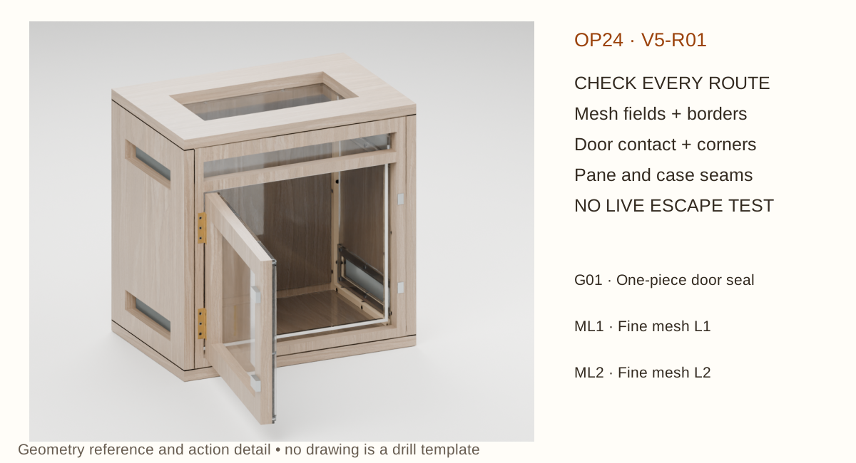
OP24 · Inspect every possible escape route
Parts: G01 One-piece door seal; ML1 Fine mesh L1; ML2 Fine mesh L2; MR1 Fine mesh R1; MR2 Fine mesh R2; A03 Fixed roof pane; A04 Fixed transom pane; A05 Door glazing and seal face
Tools ready: Magnifier; inspection light; contact-transfer materials; receiving record
Before you begin: A nice render and fine mesh do not prove containment. Do not introduce an animal to find faults.
Inspect every possible escape route · Select to enlarge
Inspect all four mesh fields, every mesh border, fixed-pane perimeter, case seam and corner. Check the door seal with both latches fully closed.
Check the door after repeated openings and representative humidity cycles. Look for panel movement, seal compression loss, loose retainers or a route around a gasket corner.
Have a competent reviewer assess containment for the actual adult and the entire enclosure. Document faults and repair/retest them; do not invent a universal safe gap from body length.
Check before continuing: H03, H04 and H06 have documented passing physical checks. No unresolved bypass or loose part remains.
Wait / hold: Animal introduction is held until these checks and commissioning pass.
THE CREATURE CORNER · SP-SLIM-01 · REVIEW DESIGN
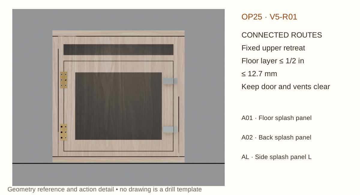
OP25 · Furnish a connected climbing route
Parts: A01 Floor splash panel; A02 Back splash panel; AL Side splash panel L; AR Side splash panel R; A04 Fixed transom pane
Tools ready: Clean dry cork/perches; shallow floor material; species care guide
Before you begin: Do not use an unsupported heavy decoration, sharp wire or adhesive that has not completed its approved cure.
Furnish a connected climbing route · Select to enlarge
Keep the floor layer at or below 1/2 inch (12.7 mm) for the stated usable-space calculation. Anchor connected climbing surfaces from low levels to the fixed upper retreat.
Leave a shaded resting area, visible hunting routes and access to drinking droplets. Keep furnishings away from the moving door, seal and latches.
Preserve enough visibility to locate the spider before opening. The guide’s empty model deliberately does not approve a particular decorating arrangement.
Check before continuing: Routes stable; no decoration blocks a vent, pushes on glazing or traps the door. Recheck usable height after furnishing.
Wait / hold: Do not disturb an occupied silk retreat during later maintenance.
THE CREATURE CORNER · SP-SLIM-01 · REVIEW DESIGN
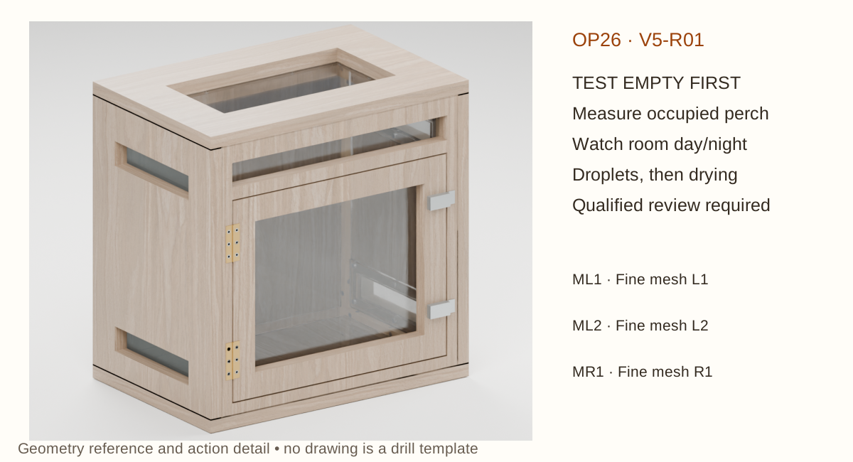
OP26 · Commission the empty enclosure
Parts: ML1 Fine mesh L1; ML2 Fine mesh L2; MR1 Fine mesh R1; MR2 Fine mesh R2; A04 Fixed transom pane
Tools ready: Temperature/RH instruments; observation log; current care guide
Before you begin: No direct sun or unreviewed heat fixture. This design has no approved lamp, UVB dose or heating port.
Commission the empty enclosure · Select to enlarge
Place the furnished empty enclosure in its intended location. Use the current regal-jumping-spider guide for starting conditions and drinking practice.
Measure the shaded occupied perch and a second location through representative day/night conditions. Observe droplets and drying without obstructing the vents to chase a humidity reading.
Confirm feeding and opening access with the actual tools and a secure catch area. Obtain qualified species review before introducing the adult.
Check before continuing: No overheating, persistent trapped moisture or inaccessible drinking/feeding area. Instrument readings and reviewer/date recorded.
Wait / hold: Observe representative conditions until the reviewer’s acceptance criteria are met; no invented fixed-duration guarantee.
THE CREATURE CORNER · SP-SLIM-01 · REVIEW DESIGN
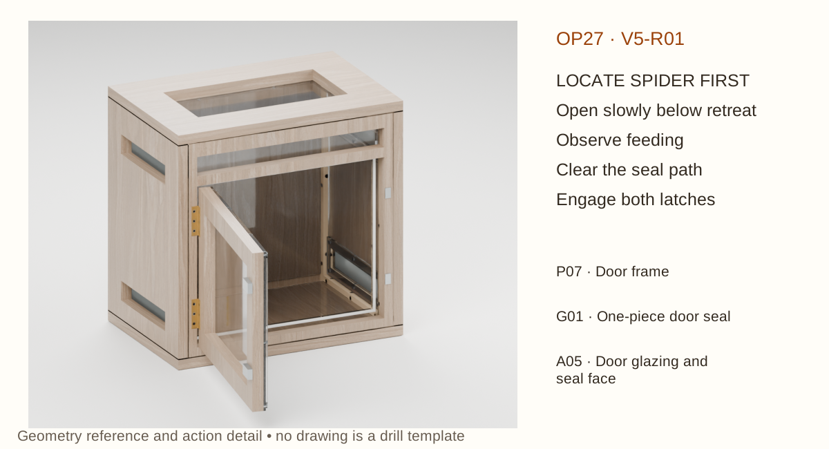
OP27 · Open, feed and clean safely
Parts: P07 Door frame; G01 One-piece door seal; A05 Door glazing and seal face
Before you begin: Find the spider before unlatching. Keep fingers and feeding tools away from the hinge and seal as the door closes.
Open, feed and clean safely · Select to enlarge
Open slowly below the fixed transom, watching the spider and its silk. Offer appropriately sized prey under observation and remove uneaten prey according to the care guide.
Wipe accessible splash panels with the acrylic supplier’s cleaning method. Keep water out of wood joints; do not spray cleaners around the animal.
Close both latches and confirm the seal is clear of legs, silk, prey and substrate. Recheck the animal’s location.
Check before continuing: Door fully closed, both latches engaged, no material trapped in the seal and the spider accounted for.
Wait / hold: Avoid routine disruption of an occupied moulting retreat.
THE CREATURE CORNER · SP-SLIM-01 · REVIEW DESIGN
OP28 · Service only with the animal rehoused
Parts: P07 Door frame; A06 Adjustable continuous door stop; AL Side splash panel L; AR Side splash panel R; A01 Floor splash panel; A02 Back splash panel; A03 Fixed roof pane
Before you begin: Rehouse the spider before removing any containment part. A fixed roof does not lift off as a routine cleaning lid.
Service only with the animal rehoused · Select to enlarge
For a door or gasket repair, support the door, remove accessible hardware/stop screws and label spacers by their original positions. Do not let the door hang on one screw.
For mesh or liner service, remove the stop to increase access; release keepers from inside. Cut cured nonstructural beads carefully and withdraw panels edge-first. If the prototype cannot demonstrate the path, revise the design.
Inspect replacement parts, restore seals and repeat receiving, cure, door-contact and containment checks. Inspect hardware, mesh and seal whenever cleaning reveals wear or damage.
Check before continuing: No part is forced through an undersized opening. The empty service path is demonstrated and every reopened interface passes its checks again.
Wait / hold: Restart full cure after any resealing. Return the animal only after all affected holds close.
Workshop drawings and measurements
How to use the workshop drawings
THE CREATURE CORNER · SP-SLIM-01 · REVIEW DESIGN
The specification is canonical in millimetres. Workshop coordinates are X right, Y toward the back and Z up, measured from the finished case’s front-left bottom corner. Part drawings show local lower-left datums; they are not to scale for printing as templates.
GLB coordinates are metres, centred on the floor, with Y up and Z toward the front. That export transformation changes no part size.
Record
Use
Part loMm + sizeMm
Assembled lower corner and size. Subtract the receiver’s lower corner to obtain a local station coordinate.
holesMm
Actual core or acrylic rectangular removals; veneer cuts are separate. Do not confuse core opening with finished opening.
Station entryMm + axis
Entry point and drilling direction. Use throughMm for the clearance stack; use the coupon result for wood pilot depth/diameter.
Hinge/latch transfer
Product drawing plus received part governs final location. Nominal envelope coordinates are explicitly not a drill release.
THE CREATURE CORNER · SP-SLIM-01 · REVIEW DESIGNOrthographic cut reference; local datum lower left · Select to enlarge
Core-cut bounds below include veneer allowance. Final visible openings are separately defined.
Opening
Lower-left offset
Opening width × height
1
1.94 × 1.94 in (49.28 × 49.28 mm)
8.06 × 4.06 in (204.72 × 103.12 mm)
Reference 1/2-inch core; receive thickness before releasing cuts
P03 · Left wall
THE CREATURE CORNER · SP-SLIM-01 · REVIEW DESIGNOrthographic cut reference; local datum lower left · Select to enlarge
Core-cut bounds below include veneer allowance. Final visible openings are separately defined.
Opening
Lower-left offset
Opening width × height
1
1.44 × 0.94 in (36.58 × 23.88 mm)
5.06 × 1.06 in (128.52 × 26.92 mm)
2
1.44 × 8.44 in (36.58 × 214.38 mm)
5.06 × 1.06 in (128.52 × 26.92 mm)
Reference 1/2-inch core; receive thickness before releasing cuts
P04 · Right wall
THE CREATURE CORNER · SP-SLIM-01 · REVIEW DESIGNOrthographic cut reference; local datum lower left · Select to enlarge
Core-cut bounds below include veneer allowance. Final visible openings are separately defined.
Opening
Lower-left offset
Opening width × height
1
1.44 × 0.94 in (36.58 × 23.88 mm)
5.06 × 1.06 in (128.52 × 26.92 mm)
2
1.44 × 8.44 in (36.58 × 214.38 mm)
5.06 × 1.06 in (128.52 × 26.92 mm)
Reference 1/2-inch core; receive thickness before releasing cuts
P06 · Fixed front
THE CREATURE CORNER · SP-SLIM-01 · REVIEW DESIGNOrthographic cut reference; local datum lower left · Select to enlarge
Core-cut bounds below include veneer allowance. Final visible openings are separately defined.
Opening
Lower-left offset
Opening width × height
1
0.44 × 0.44 in (11.18 × 11.18 mm)
10.06 × 8.31 in (255.52 × 211.07 mm)
2
0.44 × 9.19 in (11.18 × 233.43 mm)
10.06 × 1.06 in (255.52 × 26.92 mm)
Reference 1/2-inch core; receive thickness before releasing cuts
P07 · Door frame
THE CREATURE CORNER · SP-SLIM-01 · REVIEW DESIGNOrthographic cut reference; local datum lower left · Select to enlarge
Core-cut bounds below include veneer allowance. Final visible openings are separately defined.
Opening
Lower-left offset
Opening width × height
1
0.94 × 0.94 in (23.88 × 23.88 mm)
7.94 × 6.19 in (201.68 × 157.23 mm)
Reference 1/2-inch core; receive thickness before releasing cuts
A03 · Fixed roof pane
THE CREATURE CORNER · SP-SLIM-01 · REVIEW DESIGNOrthographic cut reference; local datum lower left · Select to enlarge
Receive actual material thickness and supplier tolerances before fabrication.
No rectangular opening. Drill clearance holes only from the released station schedule.
A04 · Fixed transom pane
THE CREATURE CORNER · SP-SLIM-01 · REVIEW DESIGNOrthographic cut reference; local datum lower left · Select to enlarge
Receive actual material thickness and supplier tolerances before fabrication.
No rectangular opening. Drill clearance holes only from the released station schedule.
A05 · Door glazing and seal face
THE CREATURE CORNER · SP-SLIM-01 · REVIEW DESIGNOrthographic cut reference; local datum lower left · Select to enlarge
Receive actual material thickness and supplier tolerances before fabrication.
No rectangular opening. Drill clearance holes only from the released station schedule.
A06 · Adjustable continuous door stop
THE CREATURE CORNER · SP-SLIM-01 · REVIEW DESIGNOrthographic cut reference; local datum lower left · Select to enlarge
Receive actual material thickness and supplier tolerances before fabrication.
Opening
Lower-left offset
Opening width × height
1
0.65 × 0.65 in (16.51 × 16.51 mm)
9.4 × 7.65 in (238.76 × 194.31 mm)
Stand-off spacers must be individually measured and fitted; do not fix to nominal position
RL1 · Vent retaining ring L1
THE CREATURE CORNER · SP-SLIM-01 · REVIEW DESIGNOrthographic cut reference; local datum lower left · Select to enlarge
Receive actual material thickness and supplier tolerances before fabrication.
Opening
Lower-left offset
Opening width × height
1
0.45 × 0.45 in (11.43 × 11.43 mm)
5 × 1 in (127 × 25.4 mm)
G01 · One-piece door seal
THE CREATURE CORNER · SP-SLIM-01 · REVIEW DESIGNOrthographic cut reference; local datum lower left · Select to enlarge
Receive actual material thickness and supplier tolerances before fabrication.
Opening
Lower-left offset
Opening width × height
1
0.125 × 0.125 in (3.17 × 3.17 mm)
9.45 × 7.7 in (240.03 × 195.58 mm)
Nominal 25% compression; set support from measured free ring thickness; supplier die-cut tolerance held
Fastener paths · workshop reference
THE CREATURE CORNER · SP-SLIM-01 · REVIEW DESIGN
H · 12 stations · F2
Example H1-front--0.5: receiver P06; entry X/Y/Z from that part’s lower corner: 0.3 × -0.05 × 1.72 in (7.62 × -1.27 × 43.69 mm). Direction [0, 1, 0]. Full length 0.375 in (9.52 mm); first-member stack 0.045 in (1.14 mm); actual nominal wood engagement 0.325 in (8.26 mm).
Provisional envelope: exact #2 pattern/length must match received hinge. All station coordinates and receiver IDs follow in this PDF and stations.csv; transfer to the marked local datums before drilling.
LT · 8 stations · F4short
Example LT1-0: receiver P06; entry X/Y/Z from that part’s lower corner: 10.645 × -0.03 × 2.313 in (270.38 × -0.76 × 58.74 mm). Direction [0, 1, 0]. Full length 0.375 in (9.52 mm); first-member stack 0.039 in (1 mm); actual nominal wood engagement 0.345 in (8.76 mm).
Nominal transfer; catch position from compressed seal. All station coordinates and receiver IDs follow in this PDF and stations.csv; transfer to the marked local datums before drilling.
CS · 12 stations · F4long
Example CS-L-0.7475-1.25: receiver P03; entry X/Y/Z from that part’s lower corner: 0.905 × 1.22 × 0.217 in (22.99 × 30.99 × 5.52 mm). Direction [-1, 0, 0]. Full length 0.75 in (19.05 mm); first-member stack 0.375 in (9.52 mm); actual nominal wood engagement 0.345 in (8.76 mm).
Coupon-selected pilot; no exterior breakthrough. All station coordinates and receiver IDs follow in this PDF and stations.csv; transfer to the marked local datums before drilling.
CV · 12 stations · F4long
Example CV-L-0.7475-1.5: receiver P03; entry X/Y/Z from that part’s lower corner: 0.905 × 0.718 × 0.97 in (22.99 × 18.22 × 24.64 mm). Direction [-1, 0, 0]. Full length 0.75 in (19.05 mm); first-member stack 0.375 in (9.52 mm); actual nominal wood engagement 0.345 in (8.76 mm).
Coupon-selected pilot. All station coordinates and receiver IDs follow in this PDF and stations.csv; transfer to the marked local datums before drilling.
Fastener paths · workshop reference
THE CREATURE CORNER · SP-SLIM-01 · REVIEW DESIGN
CB · 12 stations · F4long
Example CB-L-0.935-2: receiver P06; entry X/Y/Z from that part’s lower corner: 0.217 × 0.905 × 1.47 in (5.52 × 22.99 × 37.34 mm). Direction [0, -1, 0]. Full length 0.75 in (19.05 mm); first-member stack 0.375 in (9.52 mm); actual nominal wood engagement 0.345 in (8.76 mm).
Coupon-selected pilot; staggered from perpendicular side screw. All station coordinates and receiver IDs follow in this PDF and stations.csv; transfer to the marked local datums before drilling.
CF · 12 stations · F4long
Example CF-L-0.935-1.5: receiver P01; entry X/Y/Z from that part’s lower corner: 0.718 × 1.47 × 0.905 in (18.22 × 37.34 × 22.99 mm). Direction [0, 0, -1]. Full length 0.75 in (19.05 mm); first-member stack 0.375 in (9.52 mm); actual nominal wood engagement 0.345 in (8.76 mm).
Coupon-selected pilot. All station coordinates and receiver IDs follow in this PDF and stations.csv; transfer to the marked local datums before drilling.
VR · 24 stations · F4med
Example VR-L-1.275-1.275: receiver P03; entry X/Y/Z from that part’s lower corner: 0.784 × 1.245 × 0.745 in (19.92 × 31.62 × 18.92 mm). Direction [-1, 0, 0]. Full length 0.5 in (12.7 mm); first-member stack 0.254 in (6.46 mm); actual nominal wood engagement 0.216 in (5.48 mm).
Flat-head counterbore in keeper only; pan head accepted inside if coupon demands. All station coordinates and receiver IDs follow in this PDF and stations.csv; transfer to the marked local datums before drilling.
DG · 10 stations · F4med
Example DG0: receiver P07; entry X/Y/Z from that part’s lower corner: 0.21 × 0.766 × 0.185 in (5.33 × 19.46 × 4.7 mm). Direction [0, -1, 0]. Full length 0.5 in (12.7 mm); first-member stack 0.236 in (6 mm); actual nominal wood engagement 0.234 in (5.94 mm).
Pane and keeper clearance holes; no force-fit screw in acrylic. All station coordinates and receiver IDs follow in this PDF and stations.csv; transfer to the marked local datums before drilling.
Fastener paths · workshop reference
THE CREATURE CORNER · SP-SLIM-01 · REVIEW DESIGN
DS · 10 stations · F4stop
Example DS0: receiver P06; entry X/Y/Z from that part’s lower corner: 0.27 × 0.818 × 0.47 in (6.86 × 20.79 × 11.94 mm). Direction [0, -1, 0]. Full length 0.625 in (15.88 mm); first-member stack 0.288 in (7.33 mm); actual nominal wood engagement 0.307 in (7.79 mm).
Measured spacers support stop without bending it; clearance holes in acrylic. All station coordinates and receiver IDs follow in this PDF and stations.csv; transfer to the marked local datums before drilling.
RK · 10 stations · F4med
Example RK0: receiver P02; entry X/Y/Z from that part’s lower corner: 1.72 × 1.97 × -0.266 in (43.69 × 50.04 × -6.76 mm). Direction [0, 0, 1]. Full length 0.5 in (12.7 mm); first-member stack 0.236 in (6 mm); actual nominal wood engagement 0.234 in (5.94 mm).
Mechanical roof pane retainers; clearance holes in acrylic. All station coordinates and receiver IDs follow in this PDF and stations.csv; transfer to the marked local datums before drilling.
TG · 8 stations · F4short
Example TG0: receiver P06; entry X/Y/Z from that part’s lower corner: 0.47 × 0.648 × 8.97 in (11.94 × 16.46 × 227.84 mm). Direction [0, -1, 0]. Full length 0.375 in (9.52 mm); first-member stack 0.118 in (3 mm); actual nominal wood engagement 0.227 in (5.76 mm).
Pane clearance holes, washers; do not squeeze acrylic. All station coordinates and receiver IDs follow in this PDF and stations.csv; transfer to the marked local datums before drilling.
All drilling stations · 1–10
THE CREATURE CORNER · SP-SLIM-01 · REVIEW DESIGN
X / Y / Z entry coordinates from the receiving part’s lower corner. Negative entries start in an attached member outside that part. Direction +/− means along or against the named axis. Length includes the first member; wood engagement is calculated separately.
Station / receiver / drill direction
Local X × Y × Z entry
Screw length / wood engagement
H1-front--0.5 Into P06 · +Y
0.3 × -0.05 × 1.72 in (7.62 × -1.27 × 43.69 mm)
0.375 in (9.52 mm) Wood: 0.325 in (8.26 mm)
H1-front-0 Into P06 · +Y
0.3 × -0.05 × 2.22 in (7.62 × -1.27 × 56.39 mm)
0.375 in (9.52 mm) Wood: 0.325 in (8.26 mm)
H1-front-0.5 Into P06 · +Y
0.3 × -0.05 × 2.72 in (7.62 × -1.27 × 69.09 mm)
0.375 in (9.52 mm) Wood: 0.325 in (8.26 mm)
H1-door--0.5 Into P07 · +Y
0.11 × -0.05 × 1.16 in (2.79 × -1.27 × 29.46 mm)
0.375 in (9.52 mm) Wood: 0.325 in (8.26 mm)
H1-door-0 Into P07 · +Y
0.11 × -0.05 × 1.66 in (2.79 × -1.27 × 42.16 mm)
0.375 in (9.52 mm) Wood: 0.325 in (8.26 mm)
H1-door-0.5 Into P07 · +Y
0.11 × -0.05 × 2.16 in (2.79 × -1.27 × 54.86 mm)
0.375 in (9.52 mm) Wood: 0.325 in (8.26 mm)
H2-front--0.5 Into P06 · +Y
0.3 × -0.05 × 6.47 in (7.62 × -1.27 × 164.34 mm)
0.375 in (9.52 mm) Wood: 0.325 in (8.26 mm)
H2-front-0 Into P06 · +Y
0.3 × -0.05 × 6.97 in (7.62 × -1.27 × 177.04 mm)
0.375 in (9.52 mm) Wood: 0.325 in (8.26 mm)
H2-front-0.5 Into P06 · +Y
0.3 × -0.05 × 7.47 in (7.62 × -1.27 × 189.74 mm)
0.375 in (9.52 mm) Wood: 0.325 in (8.26 mm)
H2-door--0.5 Into P07 · +Y
0.11 × -0.05 × 5.91 in (2.79 × -1.27 × 150.11 mm)
0.375 in (9.52 mm) Wood: 0.325 in (8.26 mm)
Conditional layout, not a released drill template. H01/H02/H03 and offcut pilot tests must close first. Received hinge/latch patterns govern those hardware stations; regenerate this schedule if the geometry changes.
All drilling stations · 11–20
THE CREATURE CORNER · SP-SLIM-01 · REVIEW DESIGN
X / Y / Z entry coordinates from the receiving part’s lower corner. Negative entries start in an attached member outside that part. Direction +/− means along or against the named axis. Length includes the first member; wood engagement is calculated separately.
Conditional layout, not a released drill template. H01/H02/H03 and offcut pilot tests must close first. Received hinge/latch patterns govern those hardware stations; regenerate this schedule if the geometry changes.
All drilling stations · 21–30
THE CREATURE CORNER · SP-SLIM-01 · REVIEW DESIGN
X / Y / Z entry coordinates from the receiving part’s lower corner. Negative entries start in an attached member outside that part. Direction +/− means along or against the named axis. Length includes the first member; wood engagement is calculated separately.
Conditional layout, not a released drill template. H01/H02/H03 and offcut pilot tests must close first. Received hinge/latch patterns govern those hardware stations; regenerate this schedule if the geometry changes.
All drilling stations · 31–40
THE CREATURE CORNER · SP-SLIM-01 · REVIEW DESIGN
X / Y / Z entry coordinates from the receiving part’s lower corner. Negative entries start in an attached member outside that part. Direction +/− means along or against the named axis. Length includes the first member; wood engagement is calculated separately.
Conditional layout, not a released drill template. H01/H02/H03 and offcut pilot tests must close first. Received hinge/latch patterns govern those hardware stations; regenerate this schedule if the geometry changes.
All drilling stations · 41–50
THE CREATURE CORNER · SP-SLIM-01 · REVIEW DESIGN
X / Y / Z entry coordinates from the receiving part’s lower corner. Negative entries start in an attached member outside that part. Direction +/− means along or against the named axis. Length includes the first member; wood engagement is calculated separately.
Conditional layout, not a released drill template. H01/H02/H03 and offcut pilot tests must close first. Received hinge/latch patterns govern those hardware stations; regenerate this schedule if the geometry changes.
All drilling stations · 51–60
THE CREATURE CORNER · SP-SLIM-01 · REVIEW DESIGN
X / Y / Z entry coordinates from the receiving part’s lower corner. Negative entries start in an attached member outside that part. Direction +/− means along or against the named axis. Length includes the first member; wood engagement is calculated separately.
Conditional layout, not a released drill template. H01/H02/H03 and offcut pilot tests must close first. Received hinge/latch patterns govern those hardware stations; regenerate this schedule if the geometry changes.
All drilling stations · 61–70
THE CREATURE CORNER · SP-SLIM-01 · REVIEW DESIGN
X / Y / Z entry coordinates from the receiving part’s lower corner. Negative entries start in an attached member outside that part. Direction +/− means along or against the named axis. Length includes the first member; wood engagement is calculated separately.
Conditional layout, not a released drill template. H01/H02/H03 and offcut pilot tests must close first. Received hinge/latch patterns govern those hardware stations; regenerate this schedule if the geometry changes.
All drilling stations · 71–80
THE CREATURE CORNER · SP-SLIM-01 · REVIEW DESIGN
X / Y / Z entry coordinates from the receiving part’s lower corner. Negative entries start in an attached member outside that part. Direction +/− means along or against the named axis. Length includes the first member; wood engagement is calculated separately.
Conditional layout, not a released drill template. H01/H02/H03 and offcut pilot tests must close first. Received hinge/latch patterns govern those hardware stations; regenerate this schedule if the geometry changes.
All drilling stations · 81–90
THE CREATURE CORNER · SP-SLIM-01 · REVIEW DESIGN
X / Y / Z entry coordinates from the receiving part’s lower corner. Negative entries start in an attached member outside that part. Direction +/− means along or against the named axis. Length includes the first member; wood engagement is calculated separately.
Conditional layout, not a released drill template. H01/H02/H03 and offcut pilot tests must close first. Received hinge/latch patterns govern those hardware stations; regenerate this schedule if the geometry changes.
All drilling stations · 91–100
THE CREATURE CORNER · SP-SLIM-01 · REVIEW DESIGN
X / Y / Z entry coordinates from the receiving part’s lower corner. Negative entries start in an attached member outside that part. Direction +/− means along or against the named axis. Length includes the first member; wood engagement is calculated separately.
Conditional layout, not a released drill template. H01/H02/H03 and offcut pilot tests must close first. Received hinge/latch patterns govern those hardware stations; regenerate this schedule if the geometry changes.
All drilling stations · 101–110
THE CREATURE CORNER · SP-SLIM-01 · REVIEW DESIGN
X / Y / Z entry coordinates from the receiving part’s lower corner. Negative entries start in an attached member outside that part. Direction +/− means along or against the named axis. Length includes the first member; wood engagement is calculated separately.
Conditional layout, not a released drill template. H01/H02/H03 and offcut pilot tests must close first. Received hinge/latch patterns govern those hardware stations; regenerate this schedule if the geometry changes.
All drilling stations · 111–120
THE CREATURE CORNER · SP-SLIM-01 · REVIEW DESIGN
X / Y / Z entry coordinates from the receiving part’s lower corner. Negative entries start in an attached member outside that part. Direction +/− means along or against the named axis. Length includes the first member; wood engagement is calculated separately.
Conditional layout, not a released drill template. H01/H02/H03 and offcut pilot tests must close first. Received hinge/latch patterns govern those hardware stations; regenerate this schedule if the geometry changes.
All drilling stations · 121–130
THE CREATURE CORNER · SP-SLIM-01 · REVIEW DESIGN
X / Y / Z entry coordinates from the receiving part’s lower corner. Negative entries start in an attached member outside that part. Direction +/− means along or against the named axis. Length includes the first member; wood engagement is calculated separately.
Conditional layout, not a released drill template. H01/H02/H03 and offcut pilot tests must close first. Received hinge/latch patterns govern those hardware stations; regenerate this schedule if the geometry changes.
Inspection records
THE CREATURE CORNER · SP-SLIM-01 · REVIEW DESIGN
Receiving and physical release record
Hold
Actual result / date / reviewer
H01 stock/finish stack Read the audit for the acceptance method.
________________________
________________________
H02 received hardware geometry Read the audit for the acceptance method.
________________________
________________________
H03 continuous seal/compression and warping Read the audit for the acceptance method.
________________________
________________________
H04 received mesh and bypass Read the audit for the acceptance method.
________________________
________________________
H05 material compatibility and full cure Read the audit for the acceptance method.
________________________
________________________
H06 prototype fit/access/containment Read the audit for the acceptance method.
________________________
________________________
H07 empty commissioning and qualified species review Read the audit for the acceptance method.
________________________
________________________
No blank is a passing measurement. Coat/cure log, ring compression map, mesh certificate, prototype service-path photos and reviewer signature belong with this record.
THE CREATURE CORNER · SP-SLIM-01 · REVIEW DESIGN
Separate evidence statuses
Status
This candidate
RESEARCHED
candidate research recorded; H02/H05 product details open
DIMENSIONALLY CHECKED
Bounded checks recorded separately in the dimensional check record; received hardware and seal fit remain held
CALCULATION CHECKED
Mesh/layout/nominal path calculations recorded in the dimensional check record; no strength certification
DIGITALLY VALIDATED
See model, browser and PDF receipts for exact coverage; no physical or animal-use inference
Automated dimensions, render appearance and responsive UI checks are separate from construction, containment testing, animal suitability and publication. The verification record states the exact checks completed. Publication does not close any construction or animal-use hold.
Research limitations and rejected alternatives: construction audit. No universal spider-safe gap was inferred.
Finish textures: Poly Haven white oak, white maple and black walnut veneer, Jenelle van Heerden, CC0. Downloaded texture files are used under that licence; supplier product photographs are not republished.