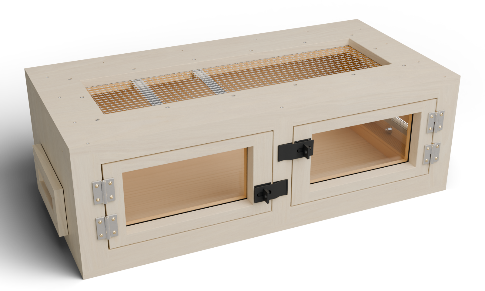
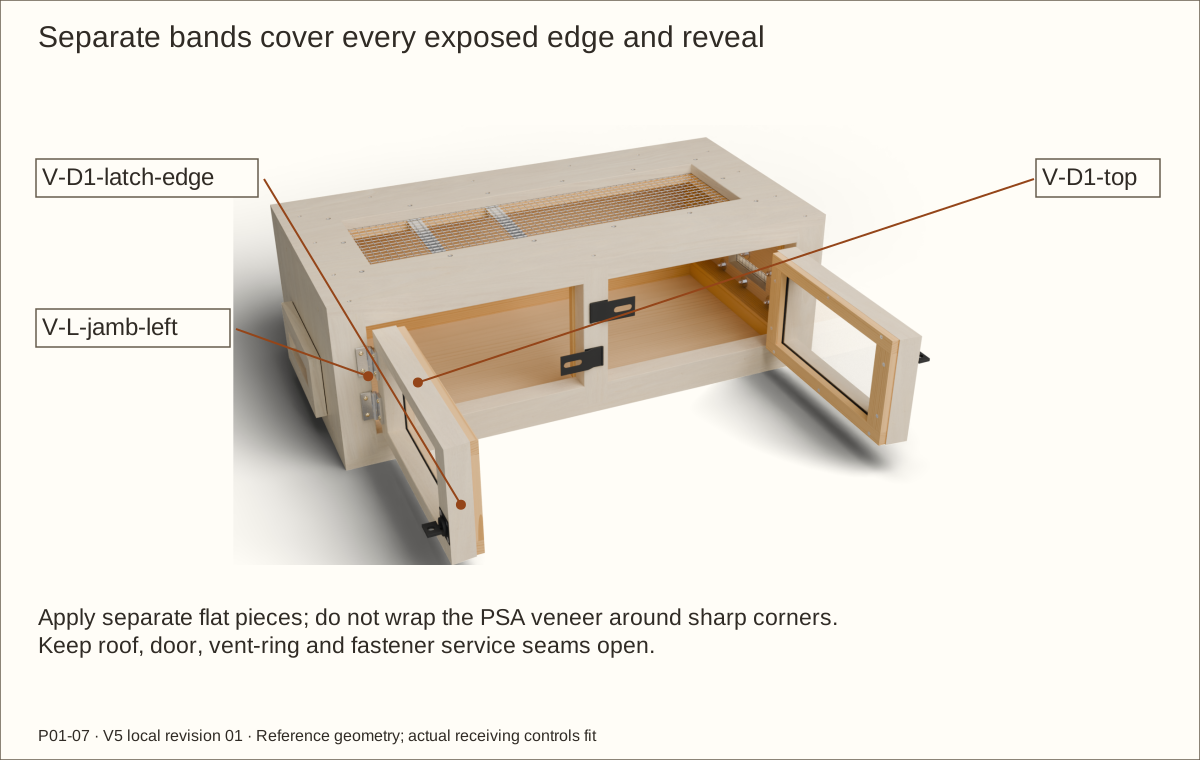
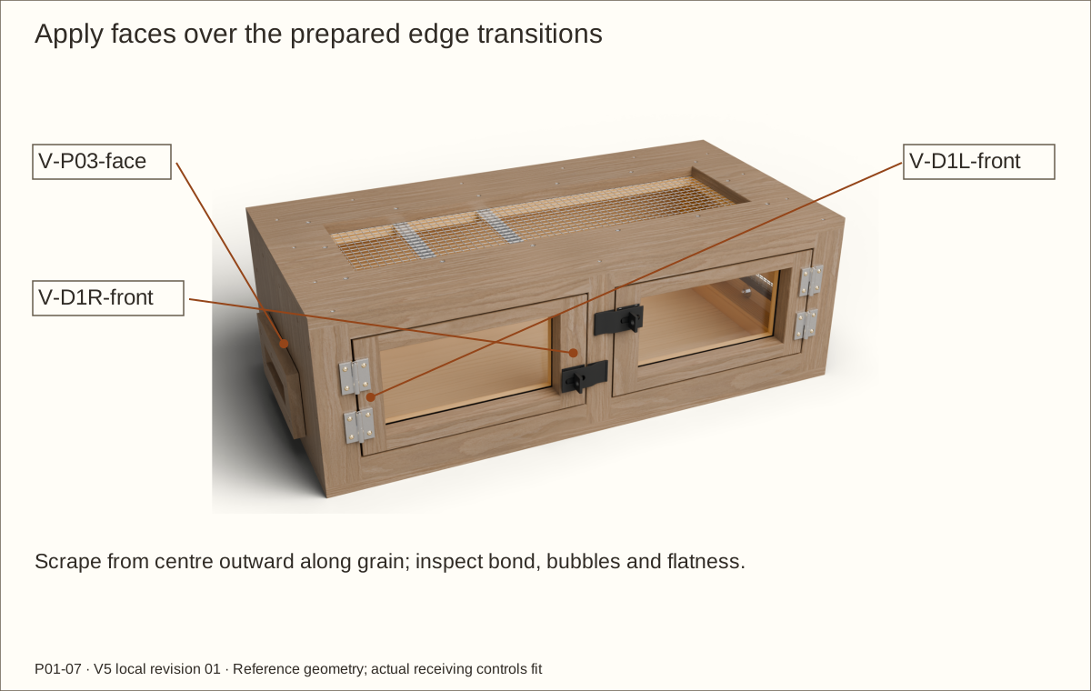
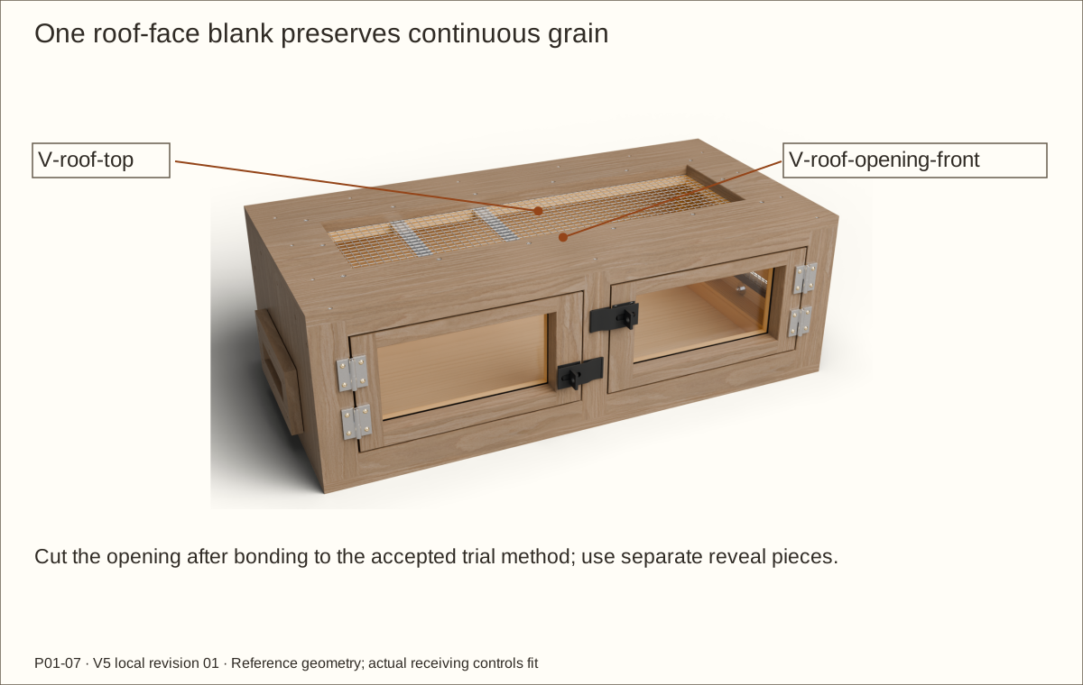
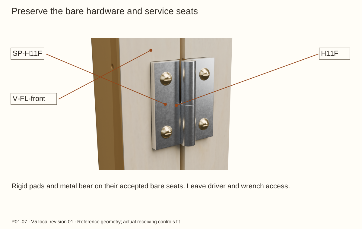
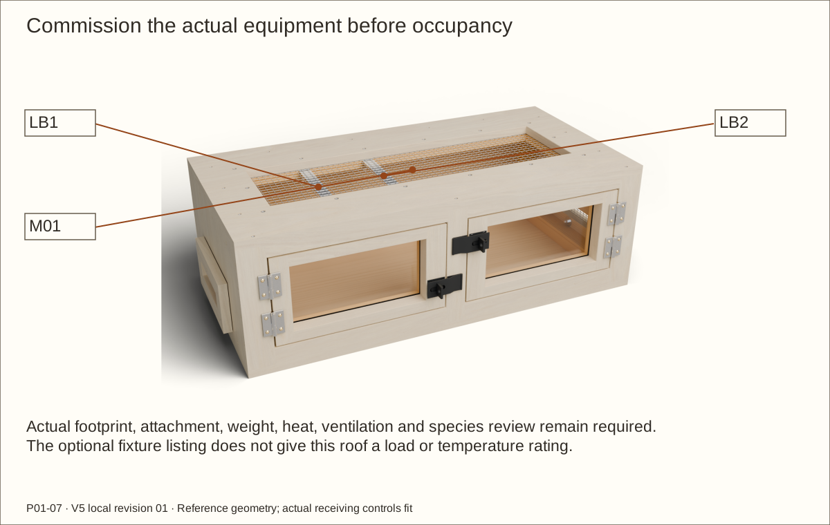
Full exterior veneer: the roof, faces, edges and reveals are included in this guide’s coordinated veneer schedule and geometry. Supplier balance, bond and actual-stack acceptance remain required. Natural grain and color vary.
About these previews
Rendered from this enclosure’s actual reference geometry. Veneer layers preserve service seams and bare hardware seats. The 3D viewer shows maple; these choices change the main picture. Texture scans by Jenelle van Heerden via Poly Haven, CC0 illustrate appearance and are not delivered veneer samples.
Two independently latched acrylic doors, a removable screened roof and low screened inlets. Follow 51 pictured operations with checks before continuing.
Construction holds: actual material and hardware acceptance, custom hinge-pad mounting, veneer balance/bond trials, prototype construction, physical testing and qualified review remain open.
Receive and trial the actual products before dependent final cuts. This is P01-07’s own shallow case and handed hardware. Recalculate every affected part if stock or hardware changes.
Measurement
Reference
Bare case
36 × 18 × 12 in (914.4 × 457.2 × 304.8 mm)
Reference covered case
36.061 in (915.95 mm) × 18.061 in (458.75 mm) × 12.061 in (306.35 mm)
Maximum covered wood, including side rings
37.696 in (957.48 mm) × 18.092 in (459.54 mm) × 12.092 in (307.14 mm)
Each bare door
14.56125 in (369.86 mm) × 7.685 in (195.2 mm)
Bare door gaps
Hinge/top/bottom 3/16 in (4.76 mm); latch 5/32 in (3.97 mm)
Minimum final operating gap
1/16 in (1.59 mm); containment acceptance is separate
Each acrylic pane
12.155 in (308.74 mm) × 0.22 in (5.59 mm) × 6.56 in (166.62 mm)
Reference lift-off stroke
1 1/16 in (26.99 mm) with leaf at 90°; received hinge and actual final clearance govern
Full cured veneer layer
Reference 0.0305 in (0.77 mm); maximum 0.046 in (1.17 mm)
Measurements: in means inches; mm means millimetres. Exact decimals are retained for fitting. Hardware projects beyond the wood envelope. Assembly coordinates begin at outside LEFT (X), outside FRONT (Y) and FLOOR UNDERSIDE (Z), unless a local part edge is named.
Tools, terms and workholding
Prepare a flat supporting bench, helpers, clamps, straight cauls, tape, square, caliper and marking knife. Use supported saw and guided router/jigsaw setups, a chisel, block plane, sliding bevel and stopped drills. Plane while wood is long and wide. Use a guarded carrier or machining service for narrow strips.
Prepare root-matched wood pilots, clearance bits and the actual head’s countersink; BOLT uses 82°. Use a #2 Phillips driver for BOLT, correctly fitted Phillips drivers for the flat wood screws, and a slotted driver for the brass S3 hinge screws. Two thin wrenches must fit the actual locknut and cover; 3/8 in (9.53 mm) is only their reference envelope. Metal needs a vise, suitable cutting/drilling tools, backer and files. Veneer needs a sharp knife, straightedge, cutting board and approved scraper.
Wear eye/hearing protection, control dust and ventilate finishes. Protect hands from sharp mesh and metal. Keep gloves, fingers and loose clothing clear of rotating machinery. Clamp small work; do not hold it beside a moving cutter.
Term
Meaning
Cleat / stile / rail
Screw-receiving strip / vertical frame member / horizontal frame member
Caul / lamination
Straight board spreading clamp pressure / layers glued together
Pilot / clearance hole
Thread-guiding hole in receiver / free screw passage through first member
Countersink / rabbet
Conical flat-head seat / shallow edge pocket
Datum / kerf
Named measuring surface / width removed by a cut
PSA / RH / BOM
Pressure-sensitive adhesive / relative humidity / bill of materials
Use the actual-stock worksheet
Record the received plywood thickness: t = ______ in / ______ mm. The equations below preserve the bare case. They assume accepted 1 1/2-inch (38.1 mm) square supports and frame depth. A changed support section needs a coordinated revision.
Part or opening
Equation, inches
Reference
P01 floor and P02 roof
36 × 18
36 × 18 in (914.4 × 457.2 mm)
P03/P04 side height; P05 back height
12 − 2t
10.56 in (268.22 mm)
P05 back and fixed-frame width
36 − 2t
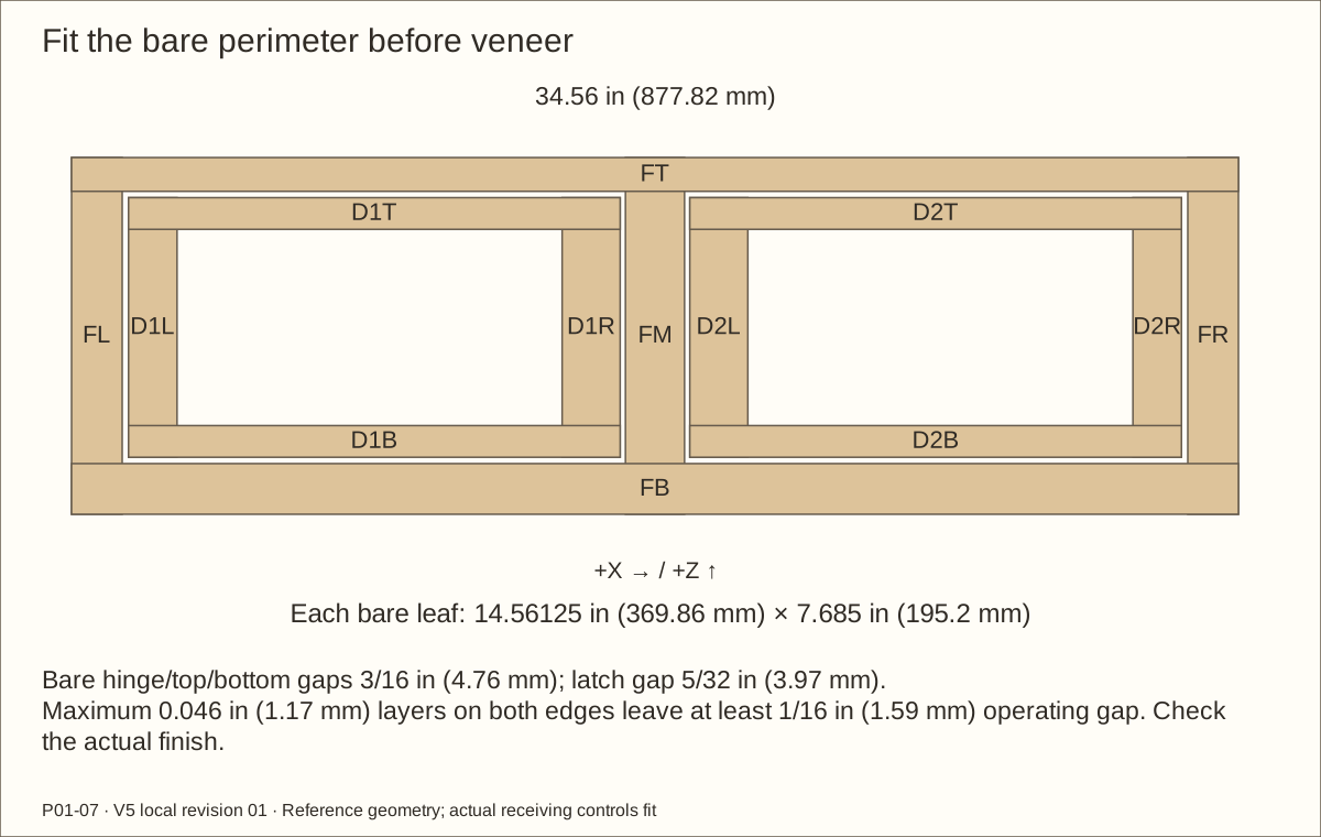
34.56 in (877.82 mm)
Each front opening width
(36 − 2t − 1.5 − 1.5 − 1.75) ÷ 2
14.905 in (378.59 mm)
Front opening height
12 − 2t − 1.5 − 1
8.06 in (204.72 mm)
Bare leaf width
Measured opening − 3/16 − 5/32
14.56125 in (369.86 mm)
Bare leaf height
Measured opening − 3/16 − 3/16
7.685 in (195.2 mm)
CLB/CLT/CRB/CRT
18 − t − 3
14.28 in (362.71 mm)
CLV/CRV
12 − 2t − 3
7.56 in (192.02 mm)
CBB/CBT
36 − 2t − 3
31.56 in (801.62 mm)
Use real mating offcuts as gauges. Recompute dependent frame cuts, pocket depths, panes, hardware locations and veneer blanks when measurements differ. Do not simply round the reference dimensions to a tape fraction.
Tools / setup: Tape, square, caliper, pencil and the tools named in this step
Before you begin: No load rating, stacking permission or species approval is supplied.
Plan support, handling and service space
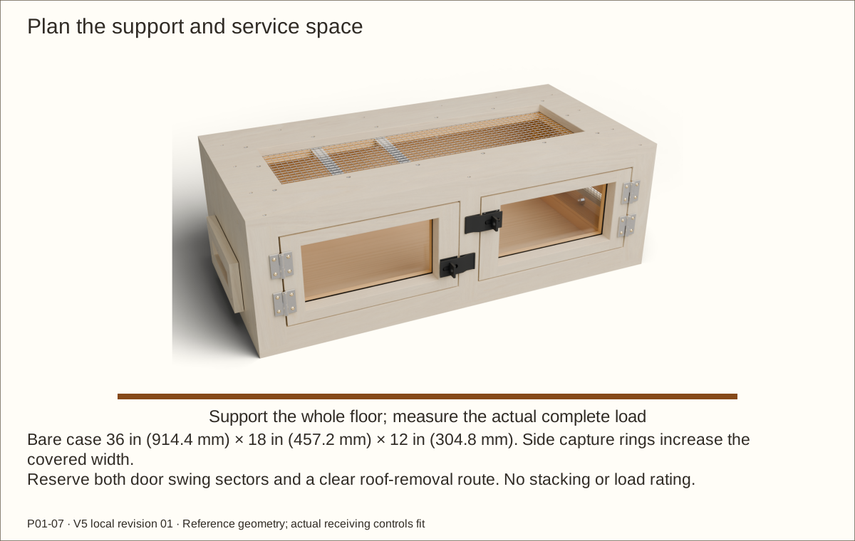
Start with the bare 36 in (914.4 mm) × 18 in (457.2 mm) × 12 in (304.8 mm) case. The fully covered side rings increase the maximum wood width to 37.696 in (957.48 mm); maximum covered depth is 18.092 in (459.54 mm) and height 12.092 in (307.14 mm). Handles and other metal project farther.
Provide a rigid, level support under the entire finished floor. Record the actual shell, contents and equipment weights, and have the furniture and floor assessed for that complete load.
Reserve both door swing sectors, room to support and lift each leaf, and a clear route to remove the roof. Rehearse turning the empty case with help onto a padded bench.
Check before continuing: Support, helpers, tool room and removal route are recorded.
Parts: Accepted material samples and the named workshop setup
Tools / setup: Tape, square, caliper, pencil and the tools named in this step
Before you begin: Unresolved product suitability is a hold, not a blank to fill with an assumed value.
Resolve the product holds
Read H01–H06 before buying or making dependent cuts. Keep supplier decisions and actual received measurements on the worksheet.
Choose one maple, white-oak or walnut veneer system. Confirm the exact backing, adhesive, sealer, topcoat and balancing method. Pressure-sensitive adhesive is shortened to PSA in the shopping list.
Use the exact handed hinges, hasps, glazing and fixing types. Record a substitution and revise every affected cut, bore and picture before proceeding.
Check before continuing: The inputs needed for the next operation have been accepted.
Parts: P01 · Floor; P03 · Left side; FM · Fixed centre stile; G1 · Acrylic pane 1
Tools / setup: Tape, square, caliper, pencil and the tools named in this step
Measure and label the stock
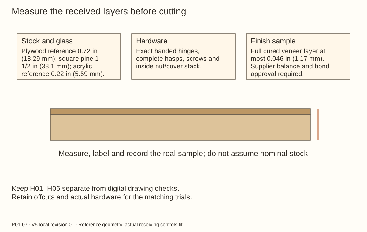
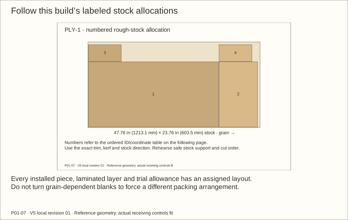
Measure each sheet at its corners and centre. Reference plywood is 0.72 in (18.29 mm) thick; the layout uses minimum 47.76 in (1213.1 mm) × 23.76 in (603.5 mm) sheets. Reject bowed, damaged or voided bearing areas.
Check actual 1 1/2 in (38.1 mm) square pine, 3/4 in (19.05 mm) × 5 1/2 in (139.7 mm) pine boards, 1/2 in (12.7 mm) × 1 1/2 in (38.1 mm) poplar, acrylic, neoprene, mesh crossings and steel. Record dimensions without rounding them to a tape fraction.
Mark each part ID, FRONT, LEFT or RIGHT, reference face A and measuring corner. Save labeled offcuts for fitting trials.
Check before continuing: Every stock type and measuring datum is identified.
Parts: Accepted material samples and the named workshop setup
Tools / setup: Tape, square, caliper, pencil and the tools named in this step
Before you begin: Do not make trapped cuts or hold small parts by hand beside a moving blade.
Prepare safe cutting and drilling setups
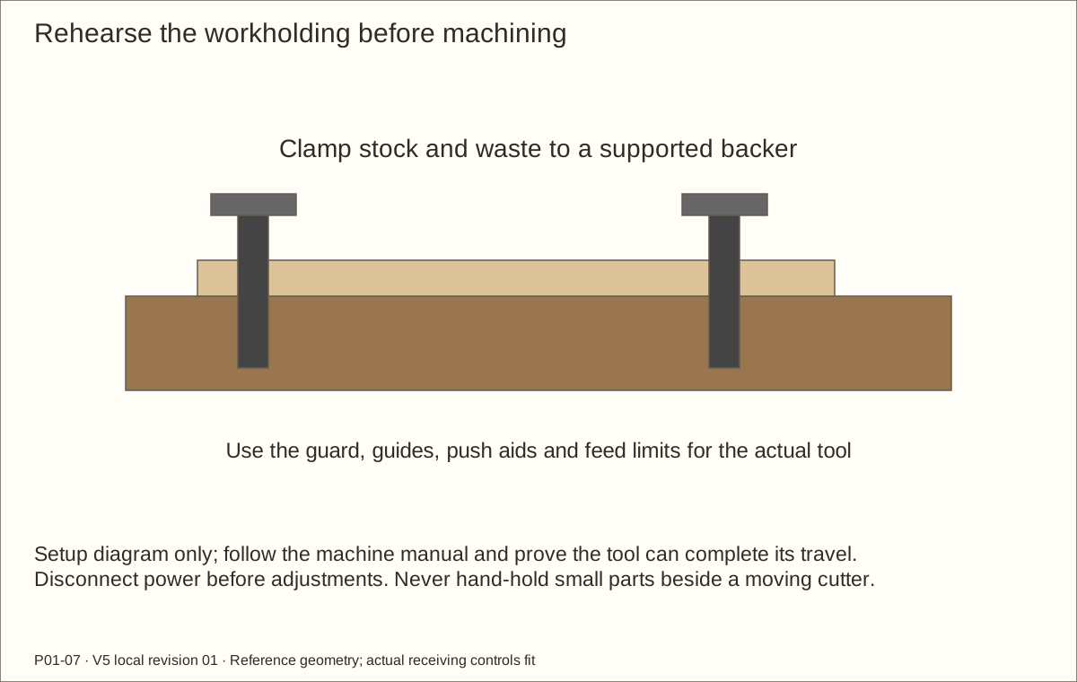
Use a flat padded bench, supported infeed/outfeed and clamps suitable for the actual tools. Rehearse the longest panel cut and case turning before machining.
Use the saw guard, riving knife and push aids required by its manual. For narrow strips, use an approved carrier or milling service; do not feed a short loose strip through a planer.
Clamp routing and drilling work to a backer, with hands away from the cutter. Disconnect the tool before changing bits, stops or guides.
Check before continuing: Stock is stable and the actual tool can complete its motion.
Parts: Accepted material samples and the named workshop setup
Tools / setup: Stopped drill, countersink, caliper, actual screws, clamps and backer
Before you begin: These are geometric references, not a torque or connection-capacity rating.
Trial pilots, clearance holes and seats
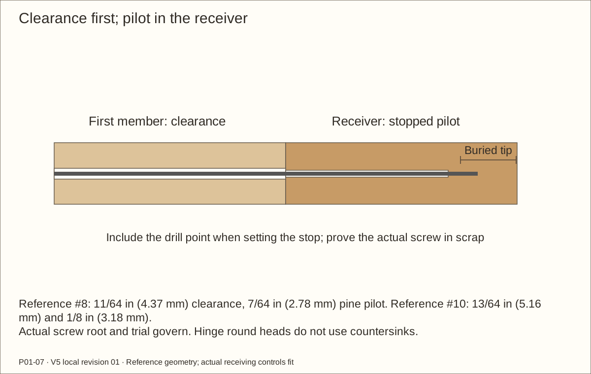
A clearance hole lets the screw pass through the first part. A smaller pilot guides its threads in the final receiver. Trial actual screws in matching offcuts before the finished parts.
The #8 reference uses 11/64 in (4.37 mm) clearance and 7/64 in (2.78 mm) pine pilot; the hasp #10 uses 13/64 in (5.16 mm) clearance and 1/8 in (3.18 mm) pilot. Received root diameter and the trial govern the pilot. Use 1/4 in (6.35 mm) through holes for the screen machine screws.
Trial the actual flat head in a matching 82-degree seat. Include the drill point when setting stopped depth. Hinge round heads use their supplied flat bearing holes; do not countersink or enlarge them.
Check before continuing: Heads seat without crushing, receivers do not split and screw points remain buried.
Parts: H11F · Door 1 hinge 1 fixed pin and leaf; H11M · Door 1 hinge 1 moving socket; L-HP-base · Hasp mounting leaf; L-ST-base · Swivel-staple mounting plate
Tools / setup: Tape, square, caliper, pencil and the tools named in this step
Before you begin: Do not use the illustrative hasp shape as a drilling template.
Trial both handed hinges and hasps
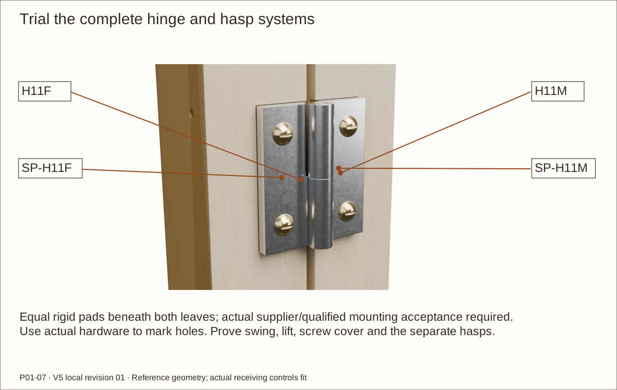
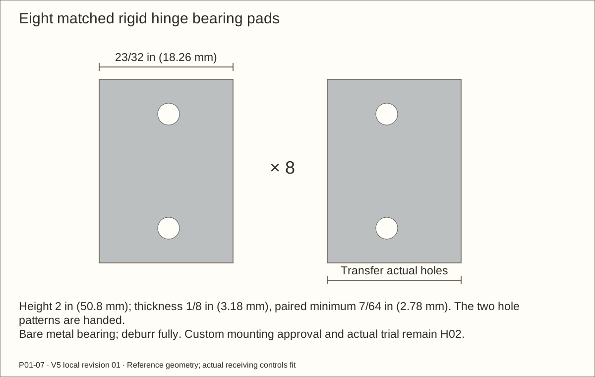
Use matching fixed- and moving-frame offcuts. Trial equal 1/8 in (3.18 mm) rigid aluminium pads under BOTH leaves; each reference pad is 2 in (50.8 mm) high × 23/32 in (18.26 mm) wide. Obtain H02 acceptance for this custom mounting. Fit 1151A81 left and 1151A82 right with fixed pins upward.
Fit the complete swivel hasp on the actual finished gap and full-width latch stile. Trace both plates; every hole and bearing edge must be supported.
Transfer the actual holes and use S3 brass slotted round-head screws. Check seating, buried tip cover, actual pad support, opening and lift stroke. Turn the swivel by hand and fully lift the hasp clear before moving the sample.
Check before continuing: Accepted hardware models, depths, support and release stroke are recorded.
Parts: D1L · Door 1 hinge stile; D1R · Door 1 latch stile; D1B · Door 1 rail; D1T · Door 1 rail
Tools / setup: Tape, square, caliper, pencil and the tools named in this step
Before you begin: Adding an unplanned backing or balancing layer changes the door and hardware fit.
Make the full-size veneer trial
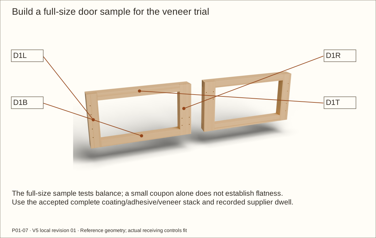
Use the reserved wood and veneer to make a representative full-size door frame with its planned coating and edge bands. A small coupon alone cannot prove panel balance.
Follow supplier-approved surface preparation, balancing, pressure and dwell. Measure the complete cured layer; the allowed maximum on any specified face is 0.046 in (1.17 mm).
Check flatness, bond and all finished gaps under the intended conditions. Record results and obtain the missing supplier answers before covering the enclosure.
Check before continuing: The full-size sample stays flat and its accepted stack fits this revision.
Required wait: Use the supplier’s confirmed dwell and full finish cure; no unsupported adhesive dwell is supplied.
Parts: G1 · Acrylic pane 1; K1FB · Door 1 dry neoprene cushion; Q1B · Door 1 glazing retainer
Tools / setup: Tape, square, caliper, pencil and the tools named in this step
Before you begin: No glue touches acrylic or cushions. Final pocket adjustment remains receiving-controlled.
Trial the cured glazing pocket
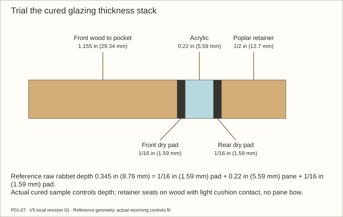
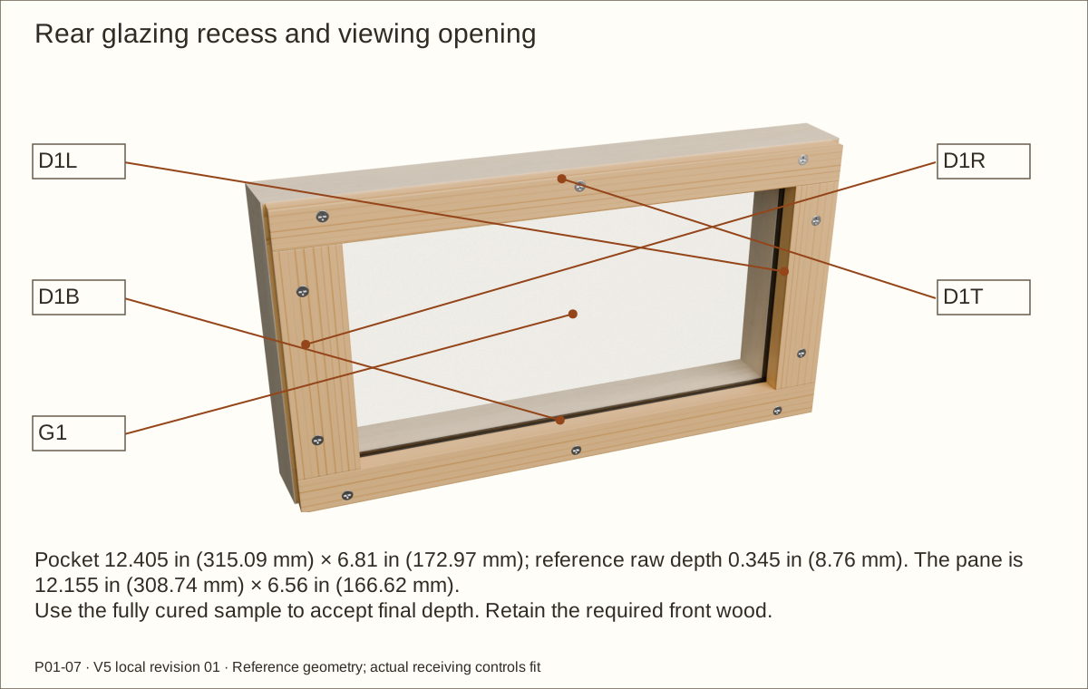
Make a same-stock sample of the rear glazing recess, called a rabbet. The reference raw depth is 0.345 in (8.76 mm) from the rear door face.
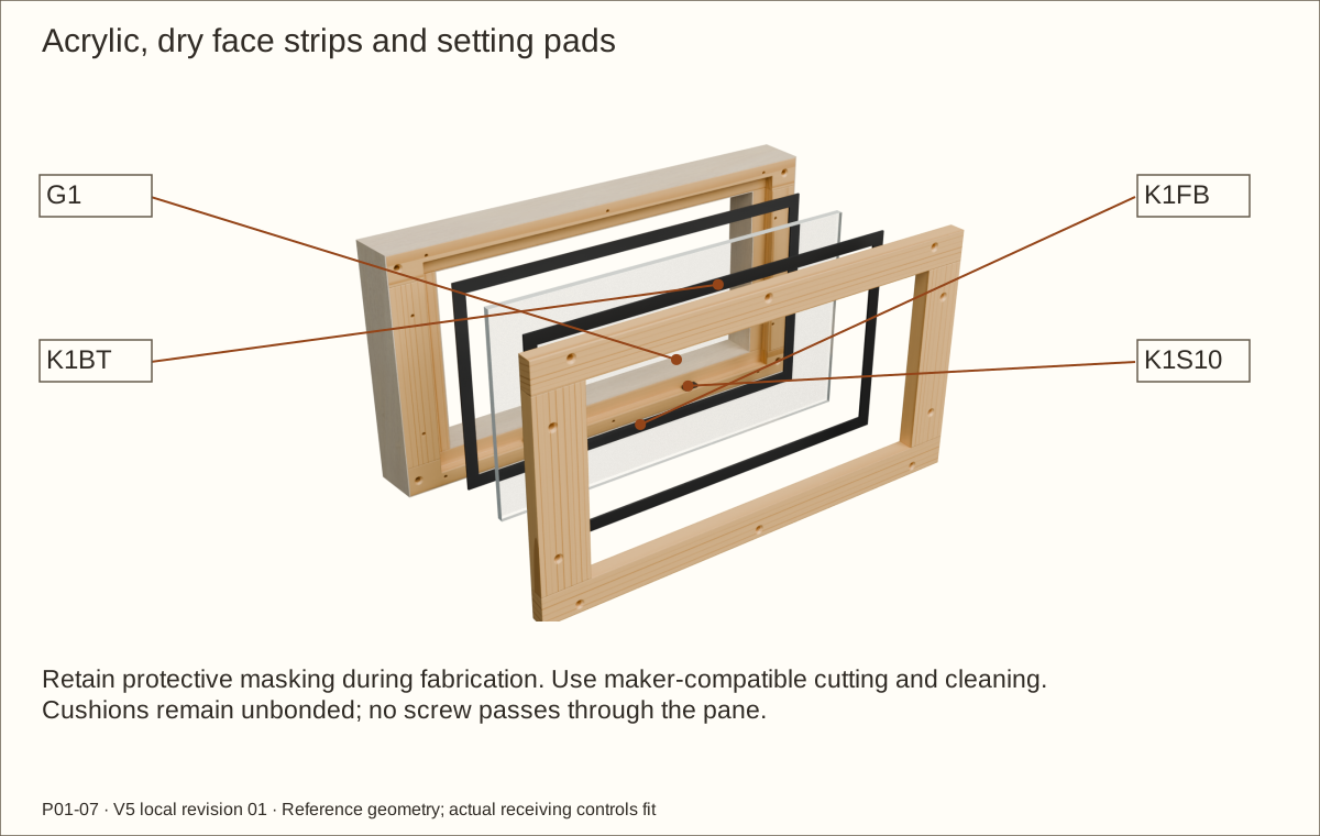
Finish and fully cure the sample. Fit the actual 0.22 in (5.59 mm) reference acrylic between two dry 1/16 in (1.59 mm) neoprene face strips and a removable poplar retainer.
Fit the pocket to the measured cured stack so the retainer seats on wood and the pane has light cushion contact without bowing. Record the accepted depth; coating and pad variation must not be forced into the nominal pocket.
Check before continuing: The pane is supported, unbowed and free of hard edge contact.
Required wait: Complete the specified finish cure before measuring the sample.
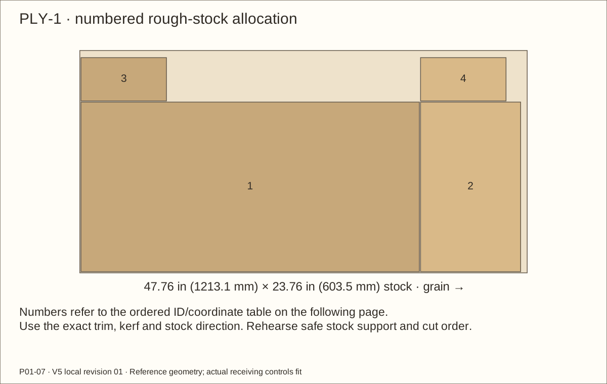
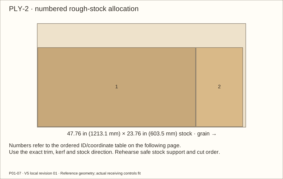
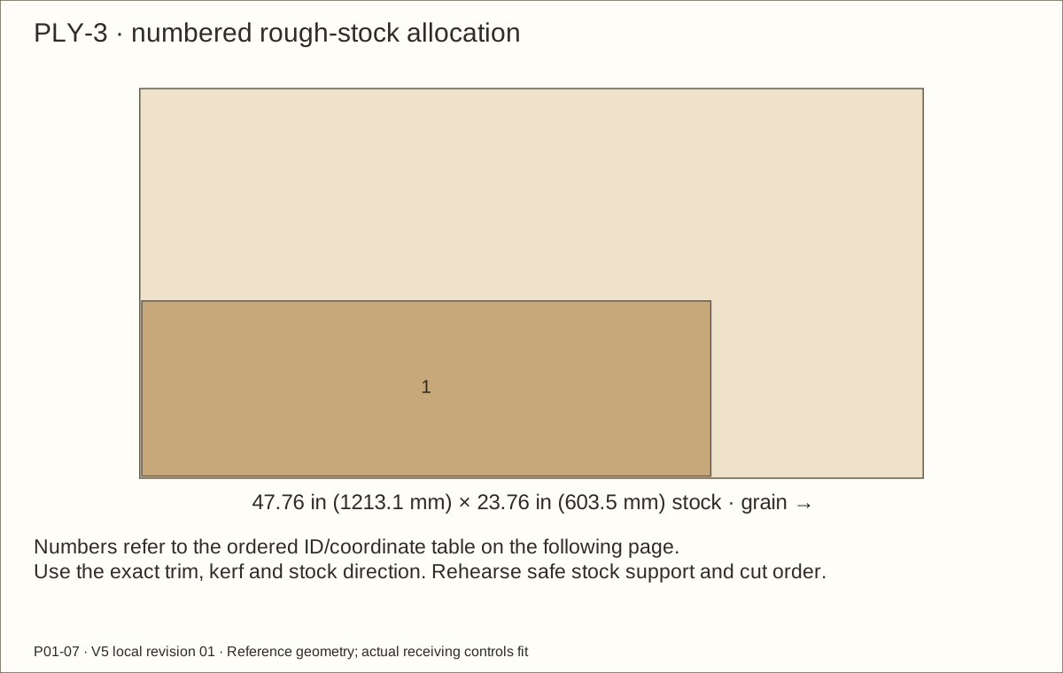
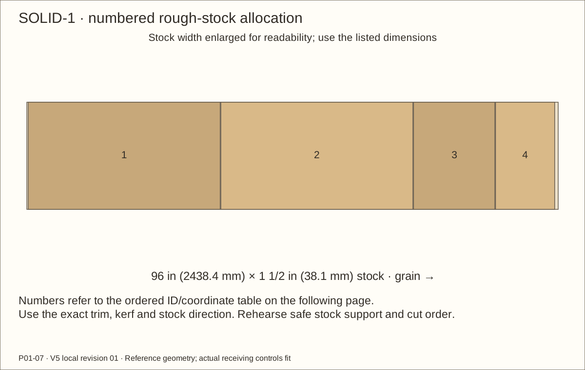
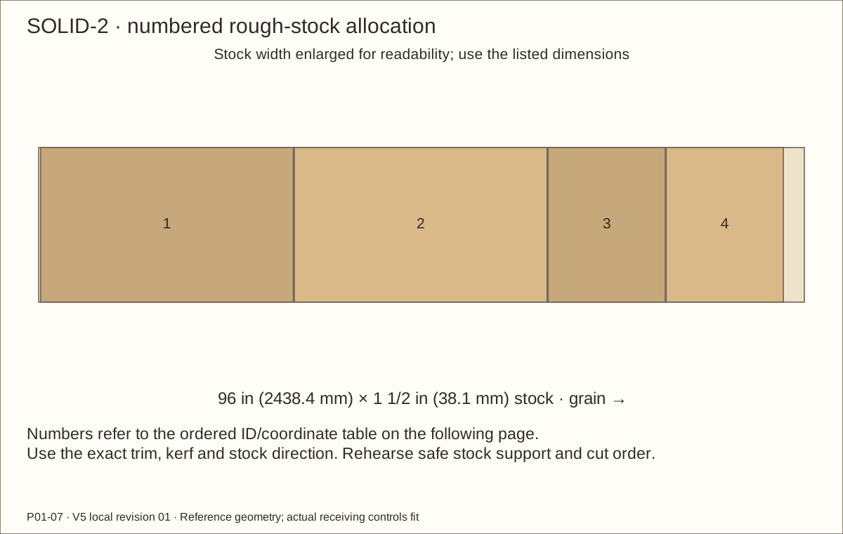
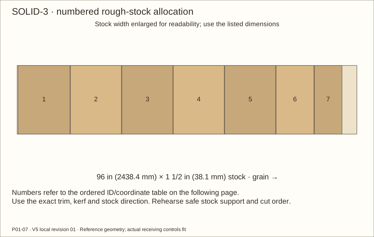
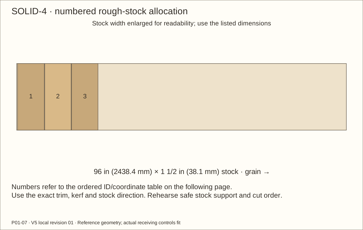
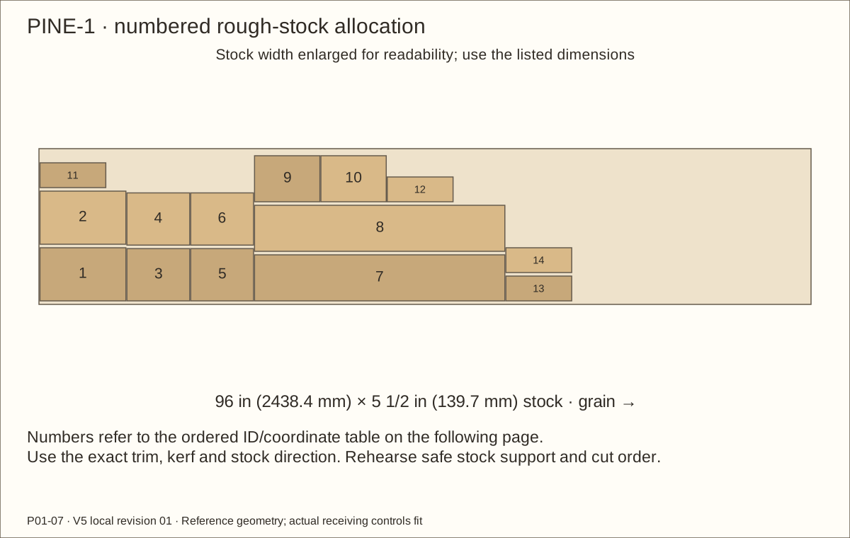
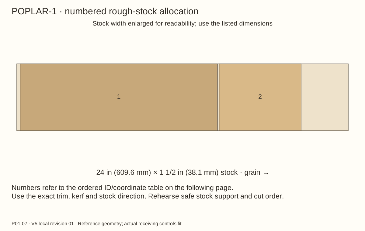
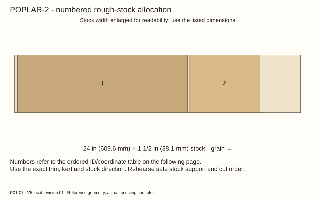
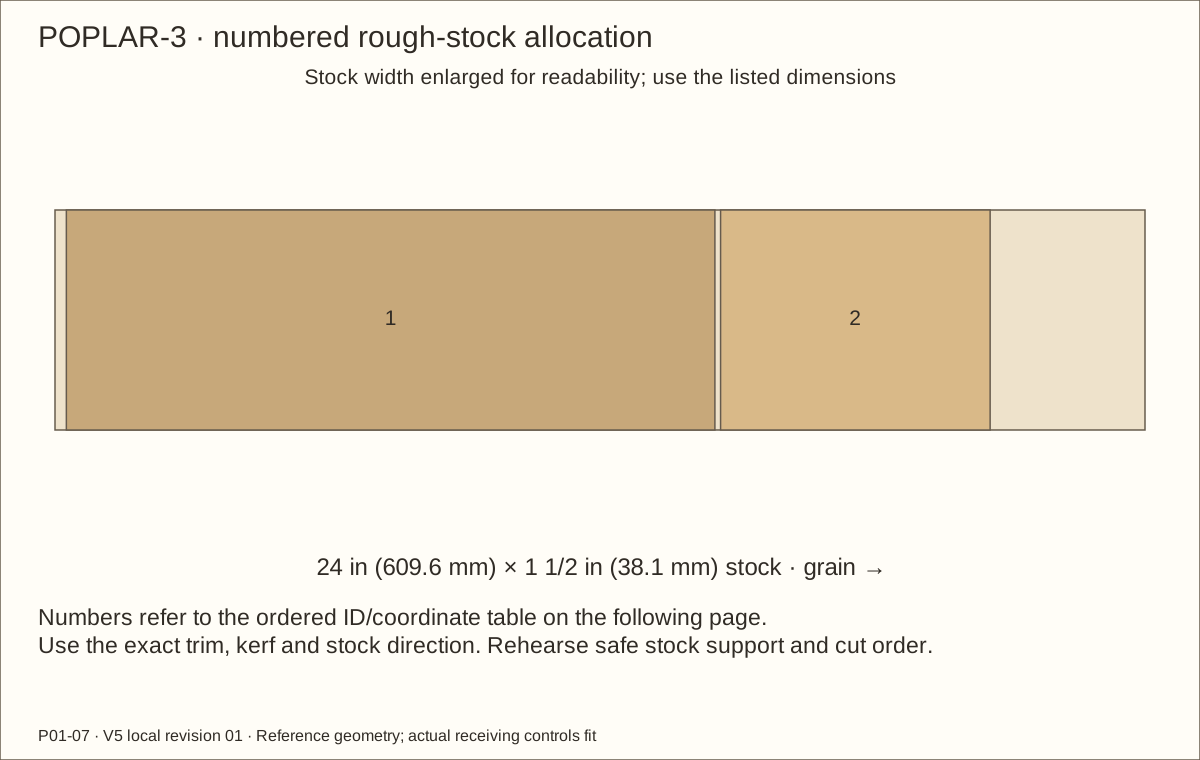
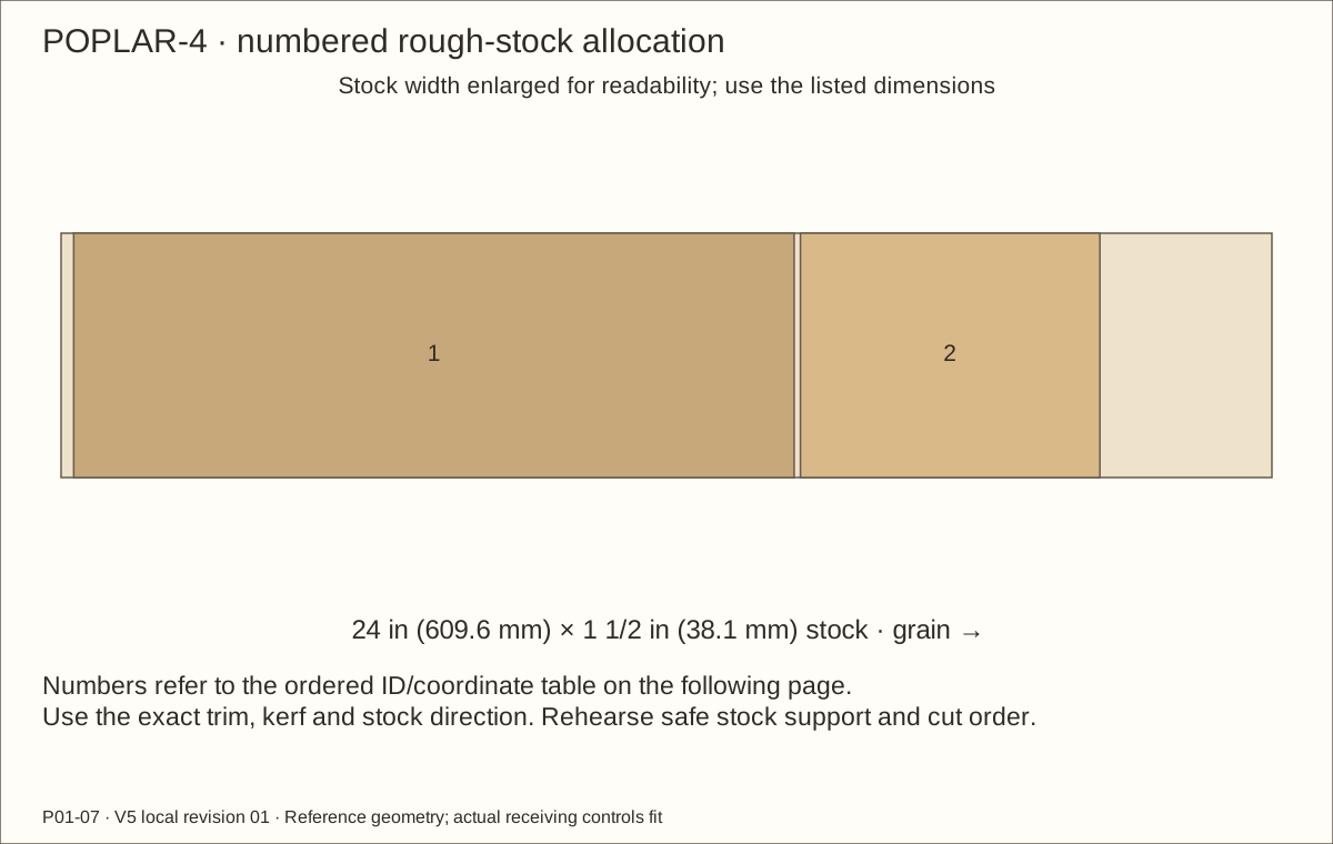
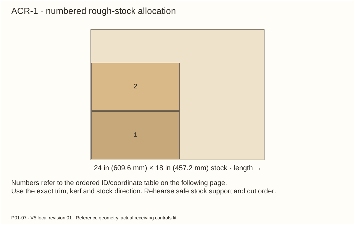
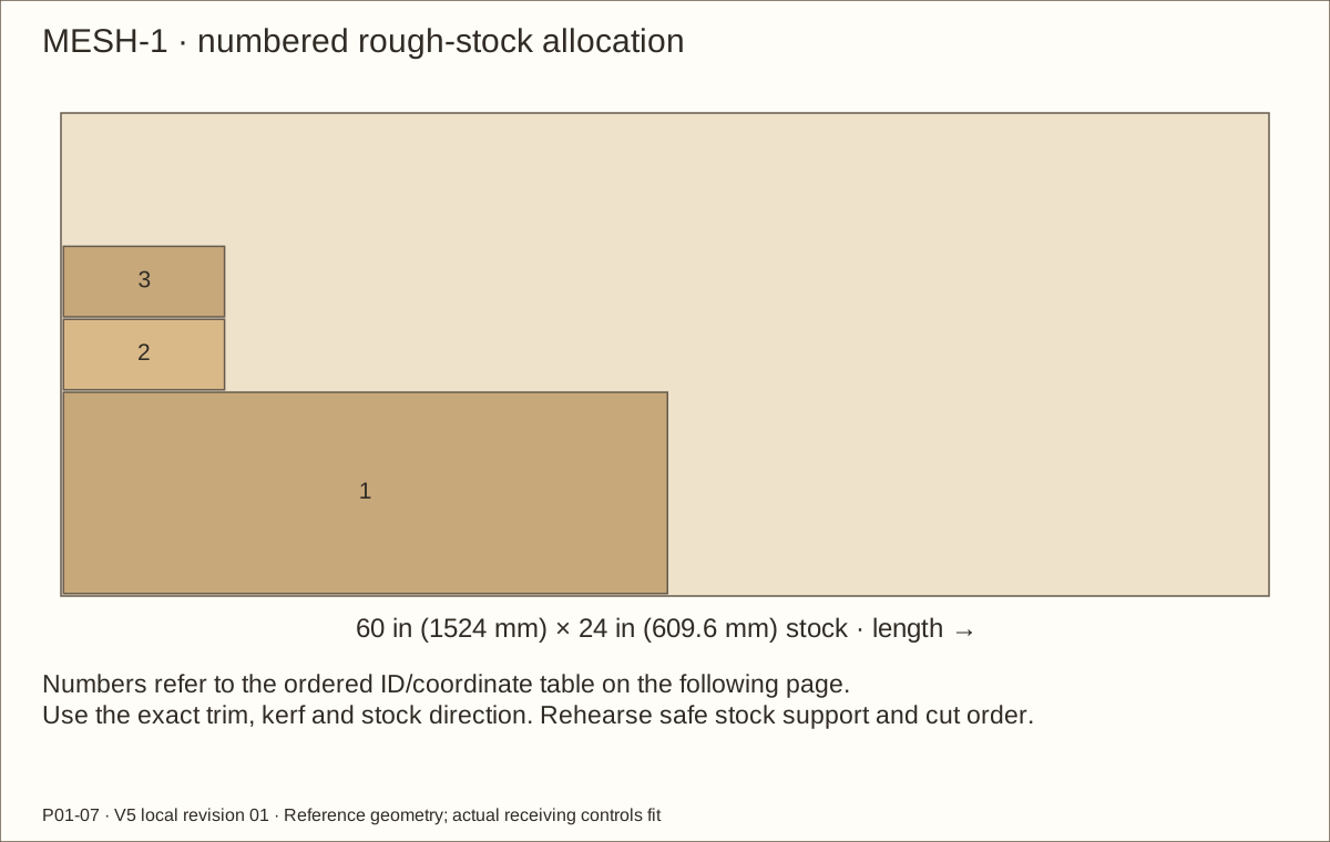
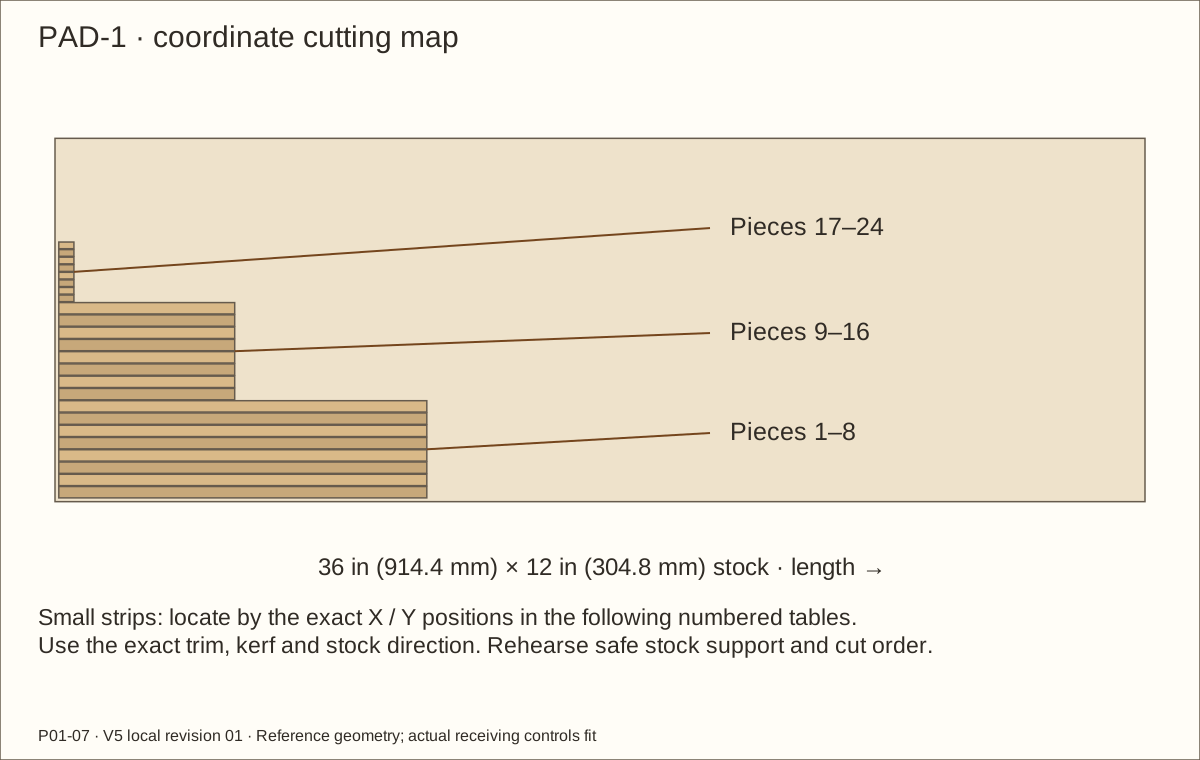
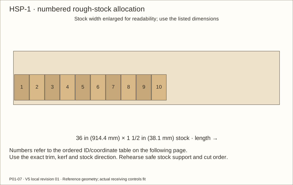
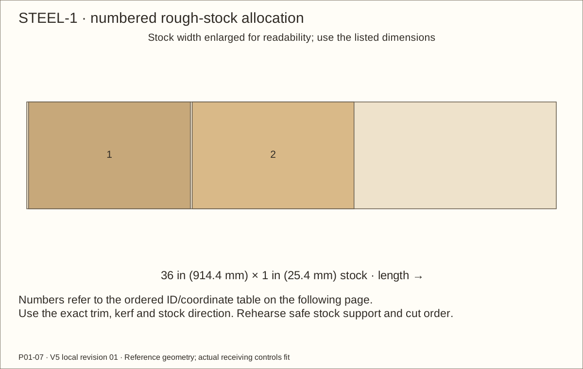
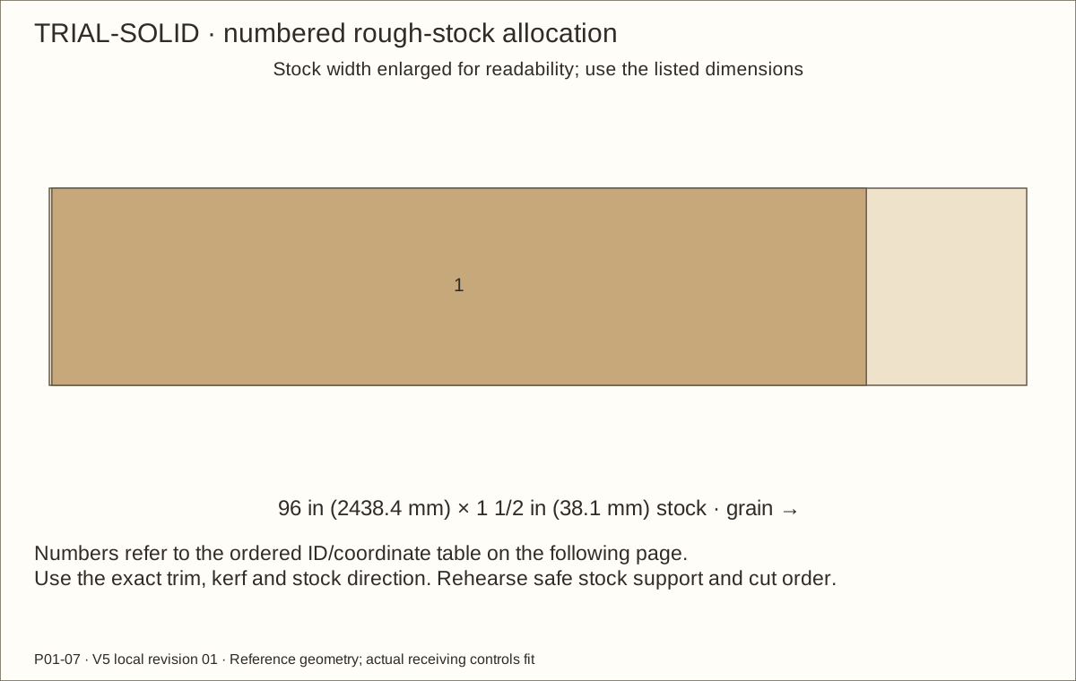
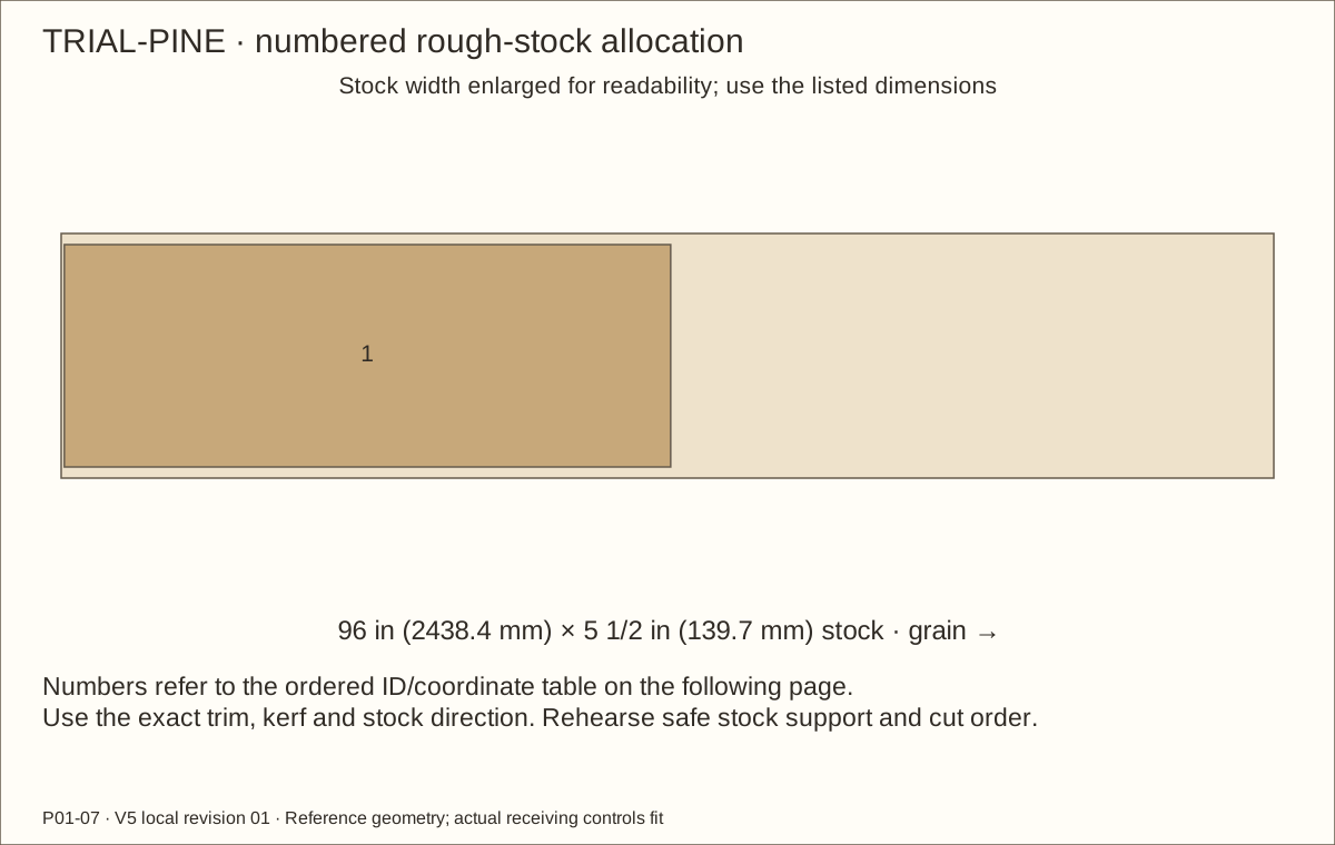
Use the numbered layouts for this build. Grain follows the layout length; keep the shown end trim and 1/8 in (3.18 mm) saw kerf, or revise the allocation for the measured blade.
Cut rough blanks, label immediately and retain the fitting allowance. Use exact finished settings from the cut list after proving actual mating stock.
Keep the dedicated trial boards separate. The three plywood sheets, working pine and trial allocations are all accounted for; do not consume trials as installed pieces.
Check before continuing: Every finished part and every laminated layer has an allocated blank.
Parts: P01 · Floor; P02 · Roof; P03 · Left side; P04 · Right side; P05 · Back
Tools / setup: Tape, square, caliper, pencil and the tools named in this step
Fit the five case panels
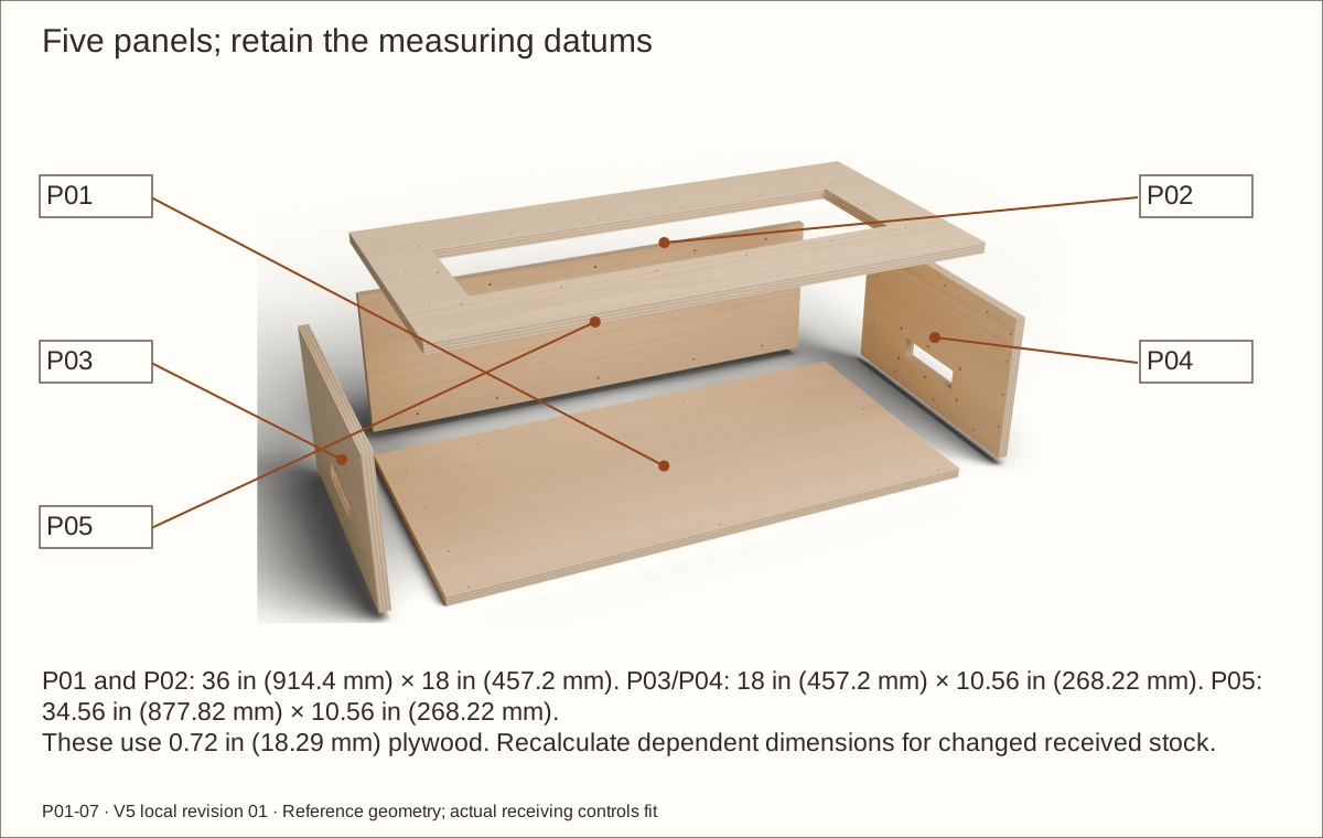
Finish P01 floor and P02 roof at 36 in (914.4 mm) × 18 in (457.2 mm). Pair P03 and P04 sides at 18 in (457.2 mm) deep × 10.56 in (268.22 mm) high for the 0.72 in (18.29 mm) reference gauge.
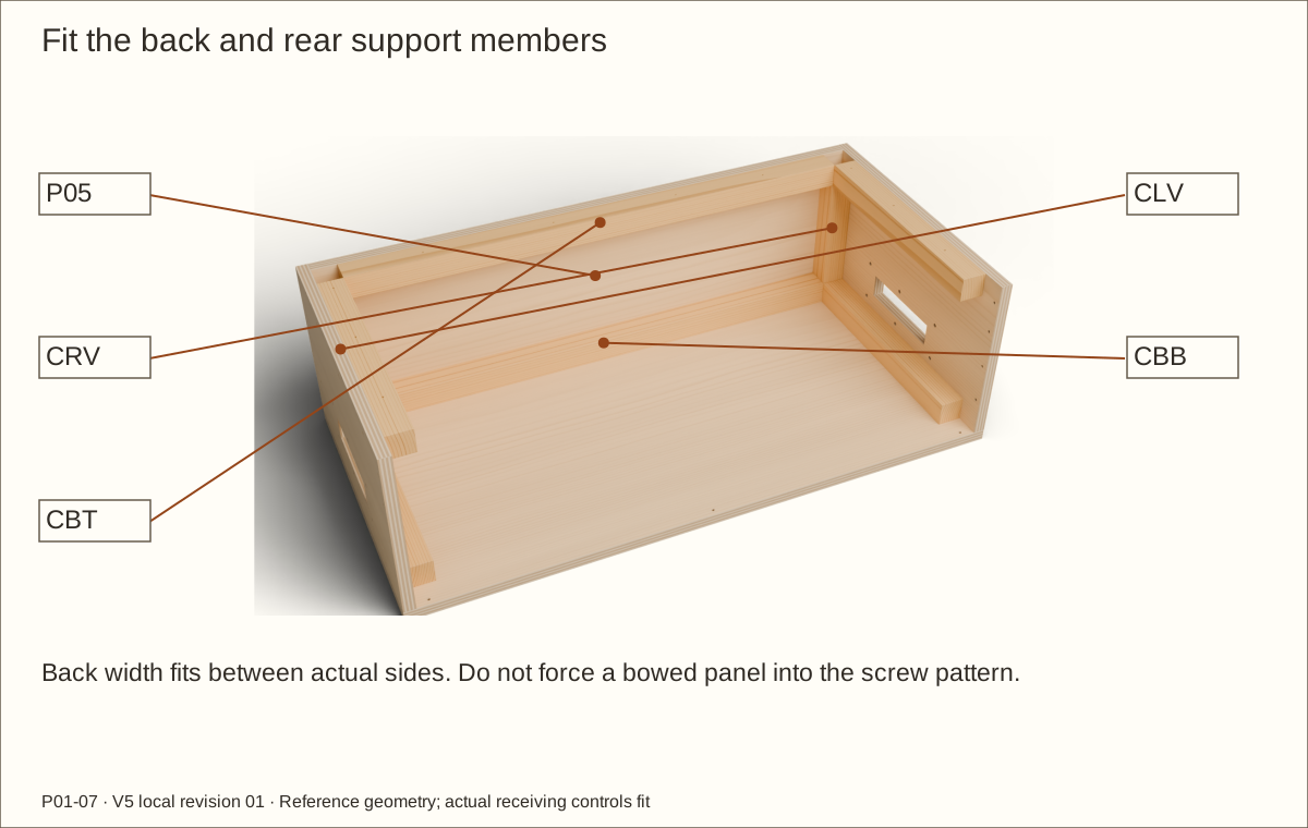
Fit P05 back between the actual sides: reference 34.56 in (877.82 mm) wide × 10.56 in (268.22 mm) high. Confirm the chain before cutting: side gauge + back width + side gauge = 36 in (914.4 mm).
Mark the outward faces and lightly remove splinters without rounding joint datums. If the received gauge changes, regenerate mating dimensions and layouts.
Check before continuing: Paired sides match and the dry panel chain closes at the intended bare size.
Tools / setup: Supported jigsaw/router setup, square, clamps and backer
Before you begin: Do not cut while the unsupported waste can fall or pinch the blade.
Cut the roof aperture
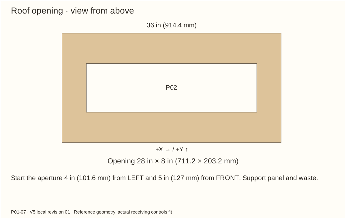
Lay P02 on a supported backer, top face visible. Mark the 28 in (711.2 mm) × 8 in (203.2 mm) opening from 4 in (101.6 mm) off LEFT and 5 in (127 mm) off FRONT.
Clamp the waste and panel, use the tool’s safe starter and guided-cut method, and keep the full border. Do not allow the last cut to tear the panel.
Check the two diagonal measurements, straight edges and the actual screen/capture overlap. Ease only splinters; do not enlarge the opening.
Check before continuing: The aperture agrees with the roof drawing and capture assembly.
Parts: P03 · Left side; P04 · Right side; V1R · One-piece inlet capture ring; V2R · One-piece inlet capture ring
Tools / setup: Supported saw/router, clamps, backer and square
Cut both side inlets and their rings
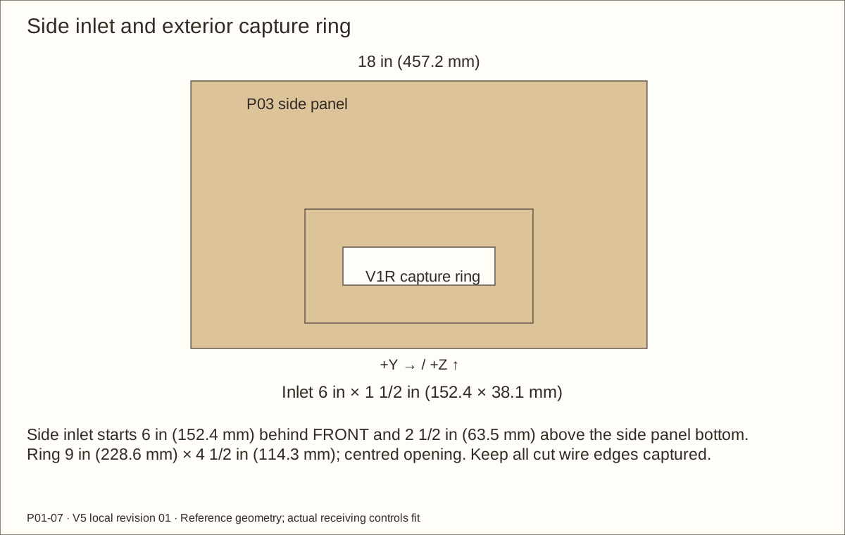
Mark each side aperture 6 in (152.4 mm) long × 1 1/2 in (38.1 mm) high, beginning 6 in (152.4 mm) behind FRONT and 2 1/2 in (63.5 mm) above that side panel’s bottom edge. This is 3.22 in (81.79 mm) above the assembled floor underside.
Make V1R and V2R as single 9 in (228.6 mm) × 4 1/2 in (114.3 mm) plywood rings, with a centred 6 in (152.4 mm) × 1 1/2 in (38.1 mm) opening. Keep continuous lands around every wire edge.
Dry-align the rings at 4 1/2 in (114.3 mm) behind FRONT and 1.72 in (43.69 mm) above the floor underside. Mark left/right; retain the datum labels for later drilling.
Check before continuing: Both openings and ring lands align without exposed cut wire paths.
Parts: CLB · Solid side B cleat; CLT · Solid side T cleat; CLV · Solid rear upright cleat; CBB · Solid back horizontal cleat; FL · Fixed L stile; FB · Fixed sill; ST0 · Vertical door stop
Tools / setup: Tape, square, caliper, pencil and the tools named in this step
Cut the supports, rails and stops
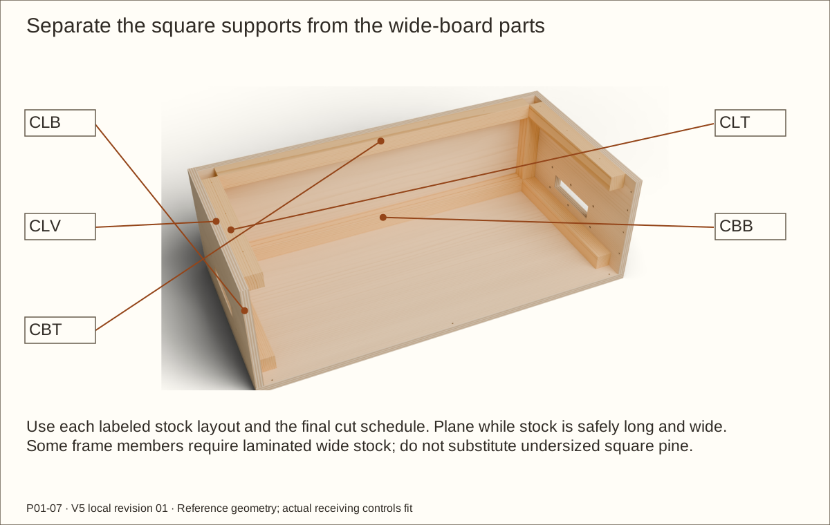
Crosscut the solid square-pine supports from their own list. Leave fitting allowance on lengths, then fit paired members against the actual panel stack.
Prepare 1 1/2 in (38.1 mm)-deep frame stock. The sill FB is 1 1/2 in (38.1 mm) high; header FT and door rails are 1 in (25.4 mm) high before the specified door perimeter fitting.
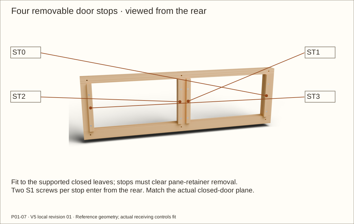
Prepare 3/4 in (19.05 mm) roof capture battens and four 1/2 in (12.7 mm)-deep door stops from the wide-board allocation. Plane safely while stock is long and wide; use a guarded fixture for final narrow ripping.
Check before continuing: All sections match the cut schedule and no short piece needs unsupported planing.
Parts: FM · Fixed centre stile; D1R · Door 1 latch stile; D2L · Door 2 latch stile
Tools / setup: Tape, square, caliper, pencil and the tools named in this step
Before you begin: This adhesive is not specified for continuous immersion or a rated structural connection.
Laminate the three wider stiles
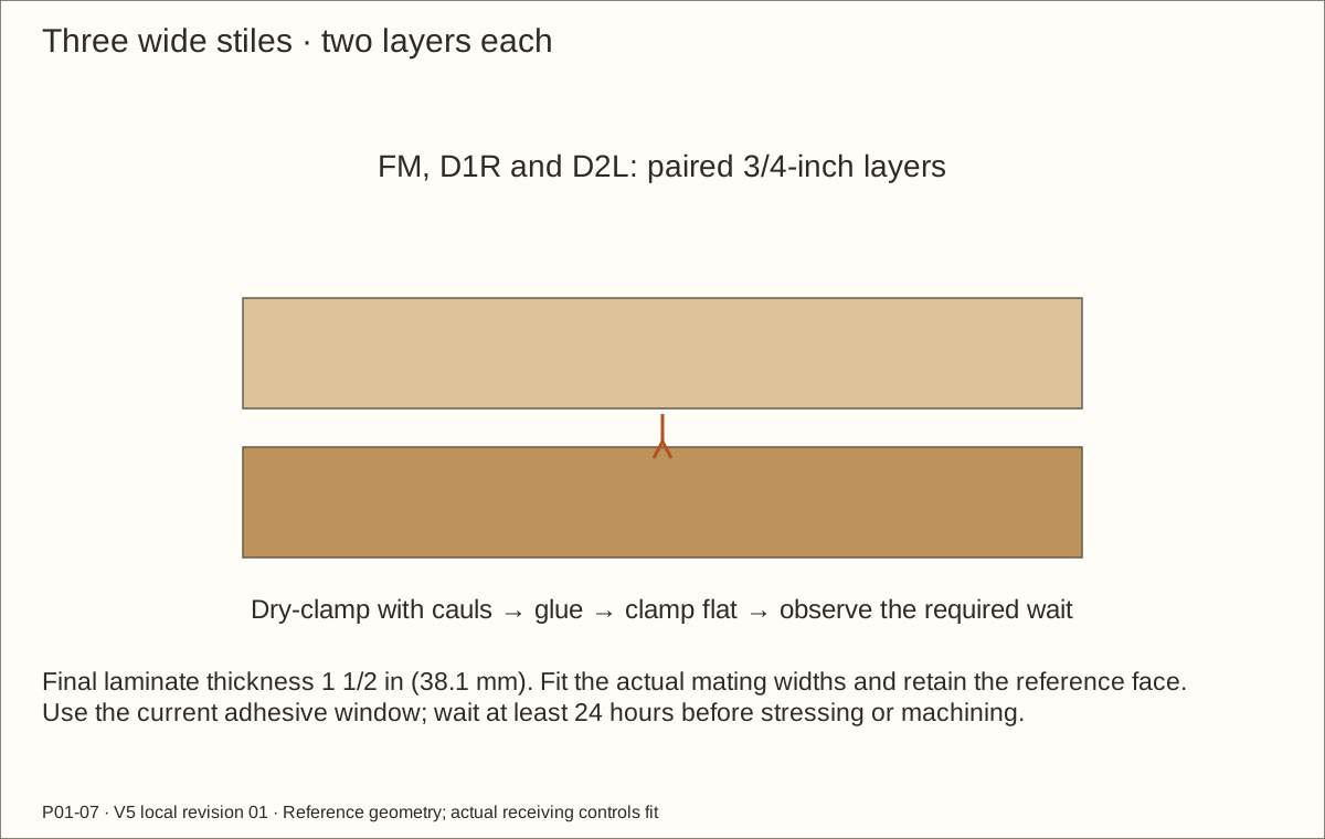
Pair two 3/4 in (19.05 mm) pine blanks for each 1 1/2 in (38.1 mm)-deep member: FM centre stile, D1R left latch stile and D2L right latch stile. Mark the outward face and matching grain.
Dry-clamp flat with cauls before glue. Spread Titebond III on clean bare mating faces and clamp evenly within its current assembly window.
At 70°F (21.1°C) and 50% relative humidity, the maker gives 8–10 minutes open time and 20–25 minutes total assembly time. Keep the glue, stock and work area above 47°F (8.3°C); conditions and the received label control.
Check before continuing: The paired layers remain aligned and flat with sound continuous contact.
Required wait: Follow the label’s clamp time; wait at least 24 hours before stressing or machining the joint. Cold or damp conditions can require longer.
Parts: FL · Fixed L stile; FM · Fixed centre stile; FR · Fixed R stile; FB · Fixed sill; FT · Fixed header
Tools / setup: Router with guide and depth stop, backer, clamps and square
Machine the fixed-frame half-laps
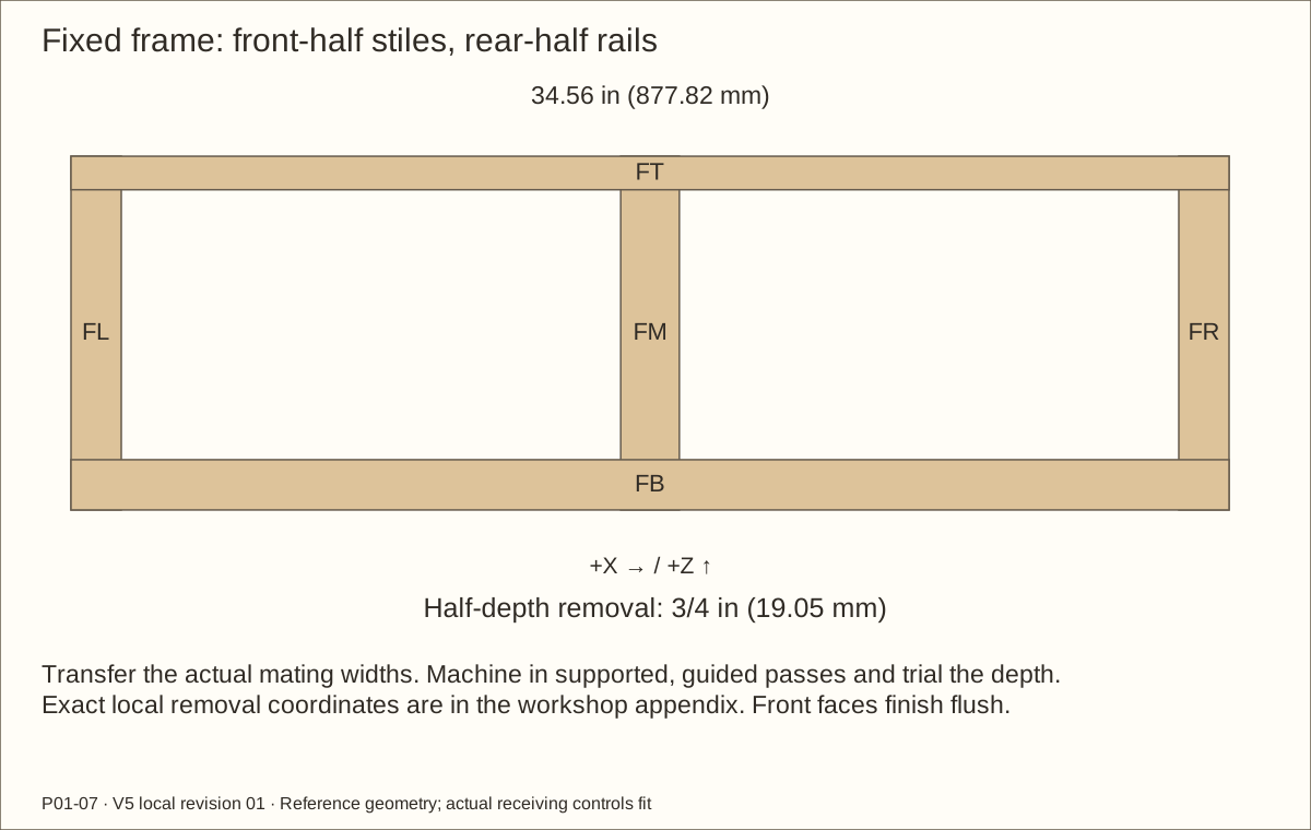
A half-lap removes half the depth from each overlapping member. In this frame, each upright keeps the FRONT 3/4 in (19.05 mm); the horizontal rails keep the REAR 3/4 in (19.05 mm) at the joints.
Mark lap widths from the actual 1 1/2 in (38.1 mm) outer stiles and 1 3/4 in (44.45 mm) centre stile. Use the fixed-frame drawing and machining bounds from the labeled corner.
Clamp a guided routing setup, prove its depth on scrap, and machine in controlled passes. Dry-fit on a flat surface; the two front openings must be equal.
Check before continuing: Lap shoulders close without forcing and both faces are flush.
Parts: D1L · Door 1 hinge stile; D1R · Door 1 latch stile; D1B · Door 1 rail; D1T · Door 1 rail; D2L · Door 2 latch stile; D2R · Door 2 hinge stile; D2B · Door 2 rail; D2T · Door 2 rail
Tools / setup: Tape, square, caliper, pencil and the tools named in this step
Machine the door-frame half-laps
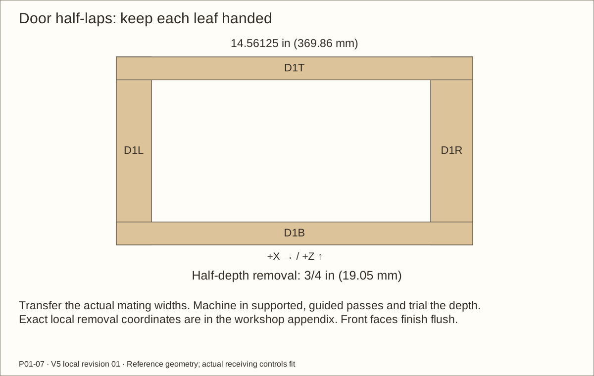
Lay out each handed leaf. The narrow stile is on its hinge side and the 1 3/4 in (44.45 mm) stile is on its latch side before perimeter fitting.
Keep the front 3/4 in (19.05 mm) on the vertical stiles and the rear 3/4 in (19.05 mm) on both full-width rails at their overlaps. Transfer the actual stile widths to the rail laps.
Use the door machining drawing, stopped router and supported stock. Check both leaves against their own raw openings without exchanging left/right members.
Check before continuing: Both dry frames lie flat; the glazing opening and wide latch land remain intact.
Parts: FL · Fixed L stile; FM · Fixed centre stile; FR · Fixed R stile; FB · Fixed sill; FT · Fixed header
Tools / setup: Tape, square, caliper, pencil and the tools named in this step
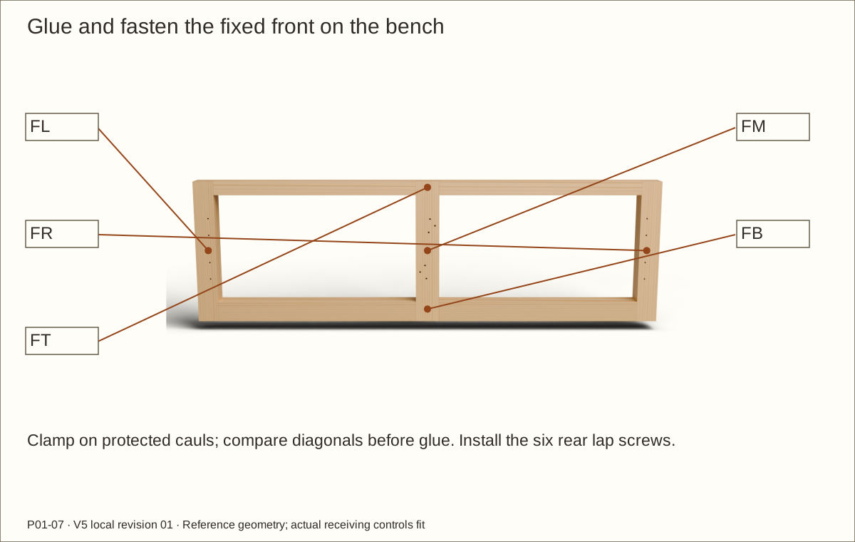
Glue and screw the fixed frame
Dry-fit the complete frame flat on protected cauls, front face downward. Confirm equal opening widths and measure both outer diagonals.
Glue bare half-laps, clamp against movement and install six S1 #8 × 1 1/4 in (31.75 mm) screws from the rear at the fixed-frame positions in the fastener station table. Clearance-drill the first layer and pilot the receiver.
Recheck shoulder contact and diagonals before the glue sets. Record the result; the proposed dry-fit diagonal difference is no more than 1/16 in (1.59 mm).
Check before continuing: The frame is flat and square with six buried, seated fixings.
Required wait: Keep clamped as the label requires; allow at least 24 hours before stressing or machining.
Parts: D1L · Door 1 hinge stile; D1R · Door 1 latch stile; D1B · Door 1 rail; D1T · Door 1 rail; D2L · Door 2 latch stile; D2R · Door 2 hinge stile; D2B · Door 2 rail; D2T · Door 2 rail
Tools / setup: Tape, square, caliper, pencil and the tools named in this step
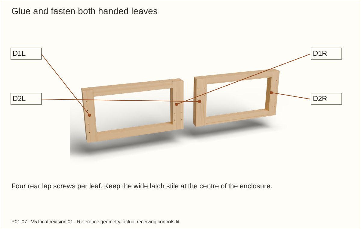
Glue and screw both door frames
Work one leaf at a time, front face downward on flat cauls. Check the joint trial and keep the latch stile on the correct side.
Glue the clean half-laps, clamp square and fit four S1 #8 × 1 1/4 in (31.75 mm) rear lap screws per leaf at its positions in the fastener station table.
Check flatness and diagonals before the adhesive sets. Keep the window opening at the original datums; later fitting removes only the specified outside perimeter.
Check before continuing: Both leaves are flat and square, with eight correctly seated lap screws.
Required wait: Follow clamp instructions and allow at least 24 hours before stressing or machining.
Parts: D1L · Door 1 hinge stile; D1R · Door 1 latch stile; D1B · Door 1 rail; D1T · Door 1 rail; D2L · Door 2 latch stile; D2R · Door 2 hinge stile; D2B · Door 2 rail; D2T · Door 2 rail
Tools / setup: Tape, square, caliper, pencil and the tools named in this step
Before you begin: Do not replace the exact reference size with its nearest tape fraction.
Fit the door perimeters for veneer
Reference fitted leaf width is 14.56125 in (369.86 mm) and height 7.685 in (195.2 mm). Remove 1/16 in (1.59 mm) from the hinge edge and each top/bottom edge, and 1/32 in (0.79 mm) from the latch edge, relative to the original blank.
Use the exact source corner positions in the door drawing. The bare hinge and top/bottom gaps become 3/16 in (4.76 mm); the latch gap becomes 5/32 in (3.97 mm). Do not move the hinge centres or window opening.
Trial the maximum approved veneer stack on both mating edges. Final operating gaps must remain at least 1/16 in (1.59 mm); actual containment is a separate animal-specific review.
Check before continuing: Both fitted leaves match their own openings with room for all finish layers.
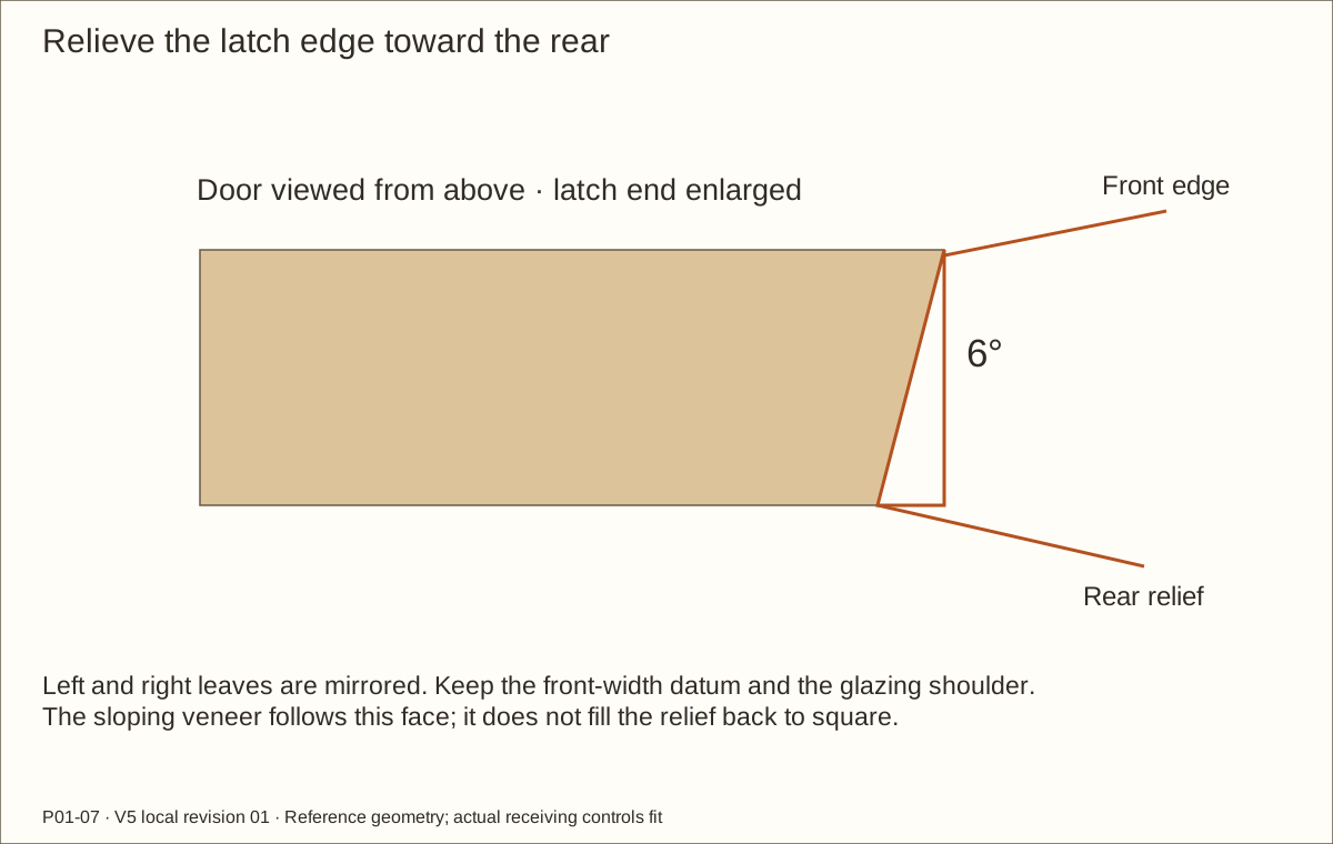
Mark the front arris, the sharp meeting line of front face and latch edge. It controls the full fitted width.
Back-bevel only the latch edge by 6 degrees: the rear edge recedes into the leaf while the front edge stays at its fitted datum. Left and right leaves are mirrored.
Use a supported guided setup and a sample first. Preserve the wide hasp-bearing face and the original glazing pocket; leave the hinge edge square.
Check before continuing: The latch edge clears during closing without reducing the required front bearing face.
Parts: D1L · Door 1 hinge stile; D1R · Door 1 latch stile; D1B · Door 1 rail; D1T · Door 1 rail; D2L · Door 2 latch stile; D2R · Door 2 hinge stile; D2B · Door 2 rail; D2T · Door 2 rail
Tools / setup: Tape, square, caliper, pencil and the tools named in this step
Rout and prove the glazing pockets
With the rear door face upward, mark each 12.405 in (315.09 mm) × 6.81 in (172.97 mm) reference pocket from the drawing. Preserve the existing 11.405 in (289.69 mm) × 5.81 in (147.57 mm) raw viewing opening.
Use the accepted cured-pocket trial to set depth; nominal raw depth is 0.345 in (8.76 mm). Clamp the whole frame to a backer and rout in supported passes.
Check the actual pane/pad/retainer stack and all screw lands before coating. Record a revised depth if the measured stack needs it and update the reference package.
Check before continuing: The pane can float inside the pocket, with continuous bearing and no hardware breakthrough.
Parts: Q1B · Door 1 glazing retainer; Q1T · Door 1 glazing retainer; Q1L · Door 1 glazing retainer; Q1R · Door 1 glazing retainer; Q2B · Door 2 glazing retainer; Q2T · Door 2 glazing retainer; Q2L · Door 2 glazing retainer; Q2R · Door 2 glazing retainer
Tools / setup: Tape, square, caliper, pencil and the tools named in this step
Cut and trial the removable retainers
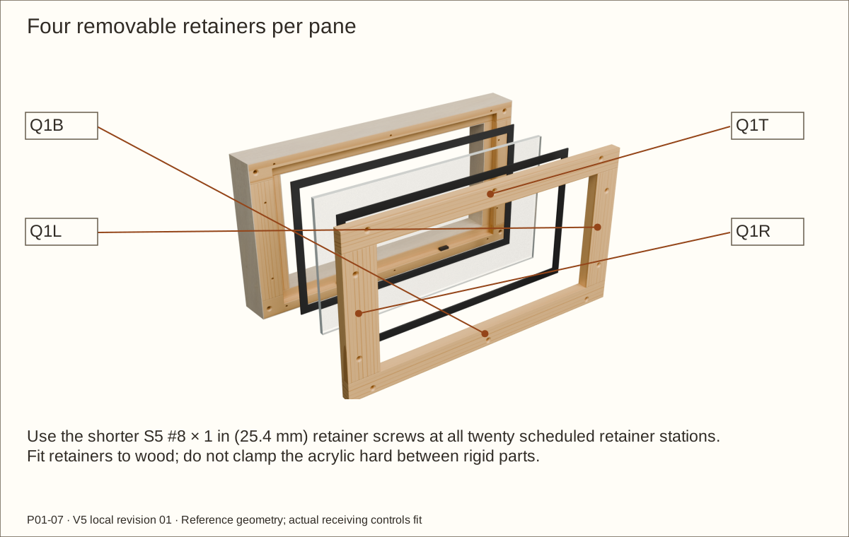
Cut the eight poplar pieces from their actual 1/2 in (12.7 mm) × 1 1/2 in (38.1 mm) stock. Use this revision’s shorter top and bottom heights after door perimeter fitting.
Dry-fit each retainer against its own door, keeping it flush inside the fitted perimeter. Transfer the twenty positions from the fastener station table; retainers must seat on wood.
Use S5 #8 × 1 in (25.4 mm) screws at every retainer position. The original longer screws are not used here; the shorter length leaves reference cover in the rear half-lapped rails.
Check before continuing: Every retainer is removable and all twenty screw tips remain covered.
Tools / setup: Tape, square, caliper, pencil and the tools named in this step
Before you begin: Do not drill the panes, bond the pads to them or clamp away the expansion space.
Prepare acrylic, face cushions and setting pads
Prepare two 12.155 in (308.74 mm) × 6.56 in (166.62 mm) reference OPTIX panes using the supplier’s cutting and edge-finishing method. Preserve protective film until final cleaning and fitting.
Cut sixteen dry face strips and eight bottom pad layers from the neoprene schedule. Two stacked 1/16 in (1.59 mm) layers make each 1/8 in (3.18 mm) bottom setting pad.
Check the nominal 1/8 in (3.18 mm) edge expansion space around each pane, including the setting pads. Actual expansion, material compatibility and light cushion contact require the glazing hold.
Check before continuing: Panes have sound edges; every pad and strip is correctly cut and labeled.
Parts: M01 · Roof steel mesh; V1M · Side inlet mesh; V2M · Side inlet mesh
Tools / setup: Tape, square, caliper, pencil and the tools named in this step
Cut and protect the mesh edges
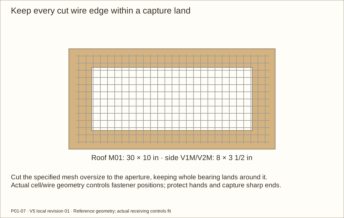
Cut the roof blank 30 in (762 mm) × 10 in (254 mm) and two side blanks 8 in (203.2 mm) × 3 1/2 in (88.9 mm). The nominal half-inch mesh is modeled with 1/2 in (12.7 mm) wire-centre spacing and 0.041 in (1.04 mm) wire, giving a 0.459 in (11.66 mm) reference clear opening. Measure the actual product; this is not a containment approval.
Use suitable snips, eye protection and cut-resistant gloves. Support the sheet and keep every cut wire end inside its continuous capture land.
Measure actual welded crossings and dry-clamp each capture. Transfer fixing centres through clear cells; never drill through or break a wire to force the drawing’s station.
Check before continuing: All mesh edges are concealed and the actual stack fits without distorting wire.
Parts: LB1 · Steel bar beneath left screen; LB2 · Steel bar beneath left screen
Tools / setup: Tape, square, caliper, pencil and the tools named in this step
Before you begin: Steel presence does not establish a safe roof or heater load.
Prepare the two roof steel strips
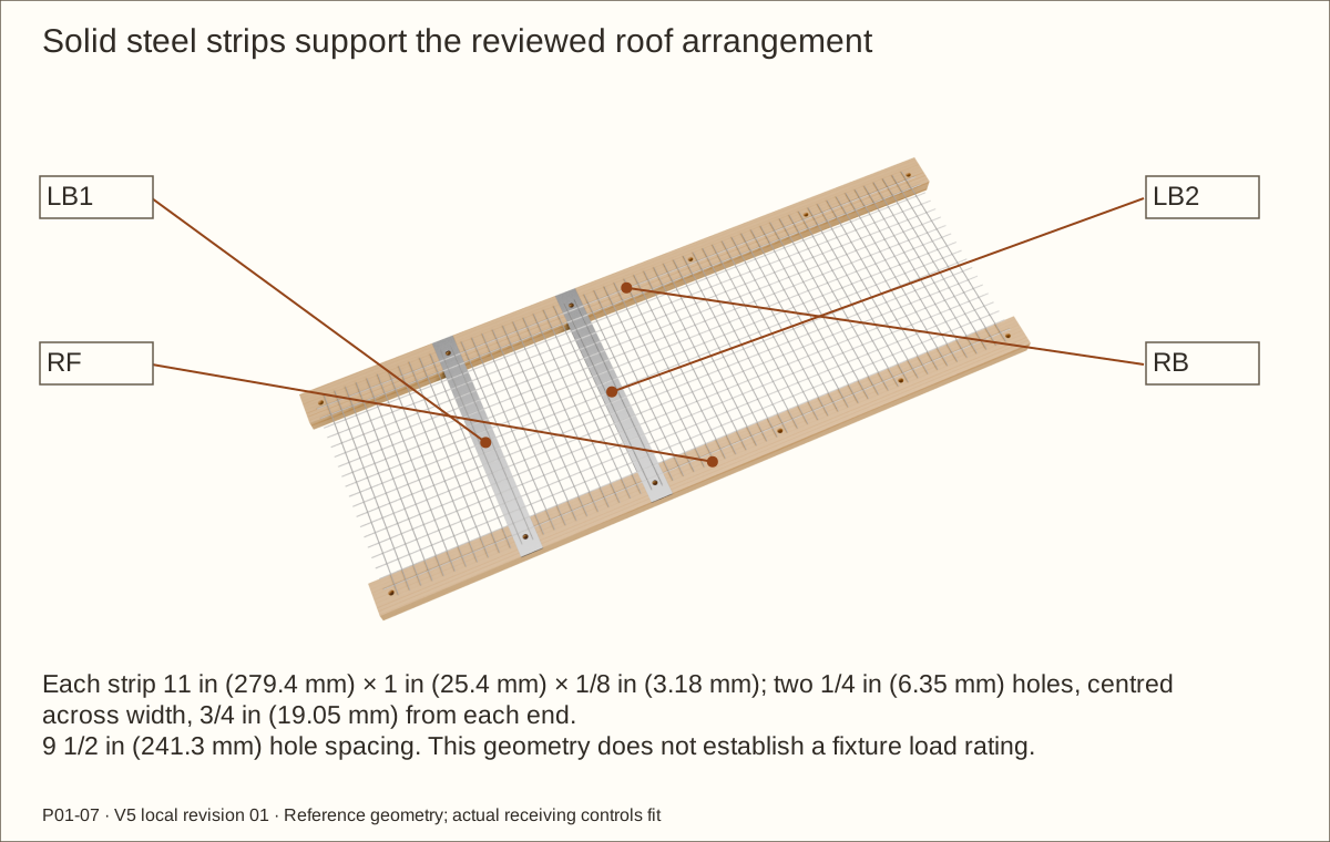
Cut two solid 11 in (279.4 mm) × 1 in (25.4 mm) × 1/8 in (3.18 mm) steel strips from the 36 in (914.4 mm) bar. Clamp while sawing and file all sharp edges.
Drill two 1/4 in (6.35 mm) holes on each width centreline, 3/4 in (19.05 mm) from each end: 9 1/2 in (241.3 mm) centre spacing. Use a drill press or stable clamped setup and deburr both faces.
Dry-fit strip centrelines 9 1/4 in (234.95 mm) and 15 1/4 in (387.35 mm) from LEFT in their coordinated seats. Transfer actual holes through the clamped roof assembly, below the screen. Inspect the actual fixture footprint separately.
Check before continuing: Both strips fit their seats and four captured holes align.
Parts: SP-H11F · Rigid hinge bearing pad H11F; SP-H11M · Rigid hinge bearing pad H11M; SP-H21F · Rigid hinge bearing pad H21F; SP-H21M · Rigid hinge bearing pad H21M
Tools / setup: Metal vise, guarded cutting/drilling setup, file, caliper and actual hinges
Before you begin: Custom pad mounting requires supplier or qualified acceptance before use.
Machine the rigid hinge bearing pads
After the H02 mounting trial is accepted, prepare eight aluminium pads from HSP. Each reference pad is 2 in (50.8 mm) high × 23/32 in (18.26 mm) wide × 1/8 in (3.18 mm) thick; two trial pads are allocated separately.
Use a metal-cutting service or a guarded, supported vise setup. Cut while the stock is securely held, deburr every edge and keep matching faces flat. Never support a narrow loose strip by hand.
Match both pad thicknesses at each hinge, minimum 7/64 in (2.78 mm). Transfer the actual two leaf holes to each pad and drill clearance holes with a backer. Keep the specified wood-bearing position; do not bridge the door gap.
Check before continuing: Every pad is flat, smooth, identified and paired; the accepted screws and lift path work.
Parts: P01 · Floor; P03 · Left side; P04 · Right side; CLB · Solid side B cleat; CLT · Solid side T cleat; CRB · Solid side B cleat; CRT · Solid side T cleat
Tools / setup: Tape, square, caliper, pencil and the tools named in this step
Dry-fit the floor, sides and supports
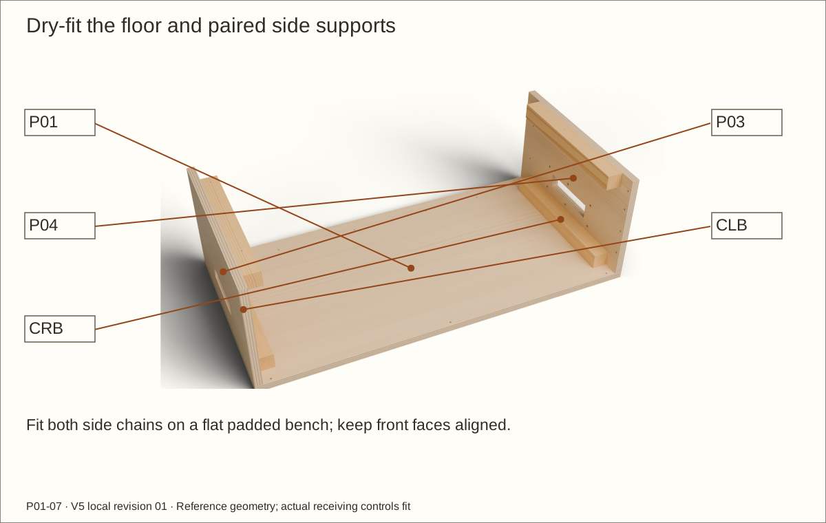
Place P01 flat on the padded bench. Stand the two sides in their correct positions and clamp temporary supports so neither can fall.
Fit the four side horizontal supports 1 1/2 in (38.1 mm) behind FRONT. Lower supports sit on the floor; upper support tops meet the roof underside at 11.28 in (286.51 mm) above the floor underside.
Check flush outer edges, equal height and the actual thickness chain. Add a helper for turning; never rely on unsecured upright panels.
Check before continuing: The dry side assembly is stable and its support faces align.
Parts: FL · Fixed L stile; FM · Fixed centre stile; FR · Fixed R stile; FB · Fixed sill; FT · Fixed header; P01 · Floor; P02 · Roof
Tools / setup: Tape, square, caliper, pencil and the tools named in this step
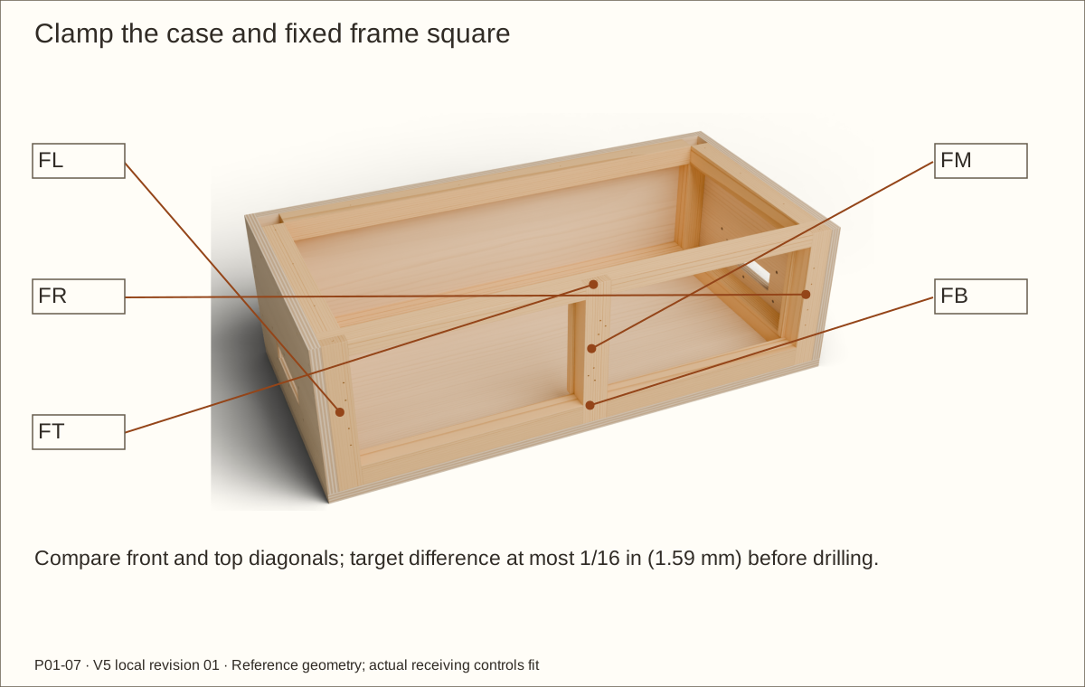
Fit the front and clamp the case square
Fit the fixed front flush with the front edges, then dry-place P02 roof. Do not glue the removable roof.
Use padded clamps across width and height to close the intended joints. Clamp bars and pads must avoid apertures, door openings and the drilling paths.
Compare front and top diagonals on the flat bench; target no more than 1/16 in (1.59 mm) difference. Record corner squareness and check both door openings before drilling.
Check before continuing: Joints are closed, roof is removable and both openings remain correct.
Parts: P01 · Floor; P03 · Left side; P04 · Right side; P05 · Back; FL · Fixed L stile; FM · Fixed centre stile; FR · Fixed R stile
Tools / setup: Tape, square, caliper, pencil and the tools named in this step
Before you begin: Recheck actual clamping after each rotation; do not remove temporary restraints early.
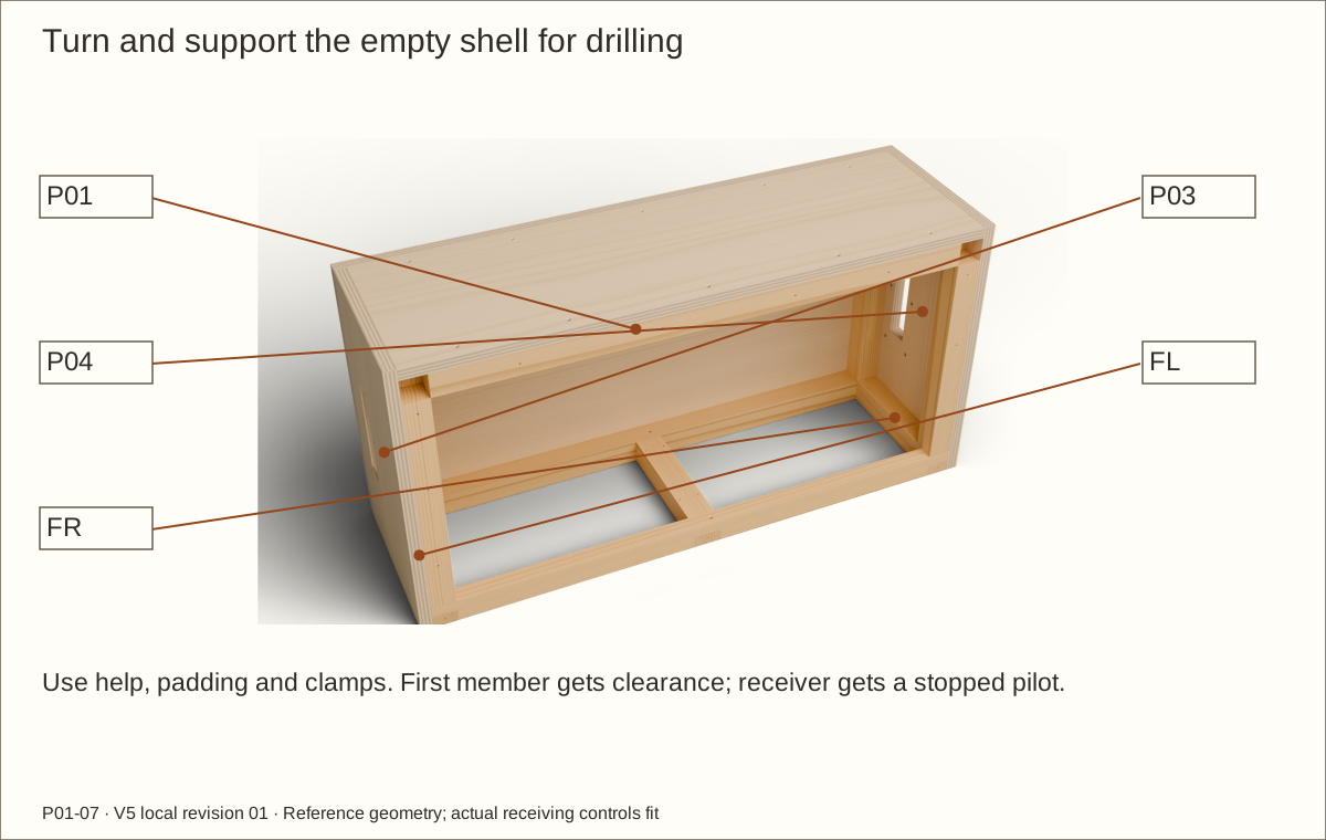
Drill the shell and front attachment
Use the shell positions in the fastener station table and sixty S2 #8 × 1 3/4 in (44.45 mm) fixings allocated across the case, front and roof. Keep roof-specific stations separate until the next step.
With the empty assembly clamped, drill each clearance entry and stopped receiver pilot. Rehearse an 8 in (203.2 mm) drill-body envelope and your actual clamp arrangement.
For floor underside stations, use helpers to place the restrained empty case on its padded back. Drill from the exposed underside; do not drill upward through the bench.
Check before continuing: Each station enters its named solid receiver, with no crossing or exposed tip.
Parts: P02 · Roof; CLT · Solid side T cleat; CRT · Solid side T cleat; CBT · Solid back horizontal cleat; FT · Fixed header
Tools / setup: Tape, square, caliper, pencil and the tools named in this step
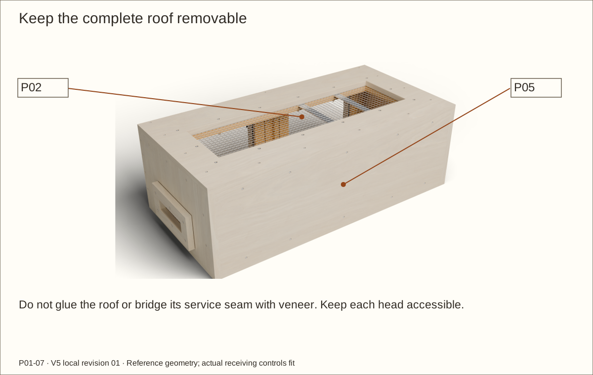
Prepare removable roof attachment
Dry-seat the roof on the square shell. Transfer its source-bound S2 stations onto the actual receiving supports.
Clearance-drill through P02 and stop the pilots inside the receivers. Trial the flat heads flush in bare wood; keep these service recesses open through later veneer.
Label every roof screw and lift off the roof for the screen work. No glue or veneer bridges this service joint.
Check before continuing: Roof can be repeatedly seated and removed without stripping its pilots.
Tools / setup: Tape, square, caliper, pencil and the tools named in this step
Before you begin: A countersink that cuts a void, edge or wire requires repair/redesign before continuing.
Machine the exterior screen-fixing seats
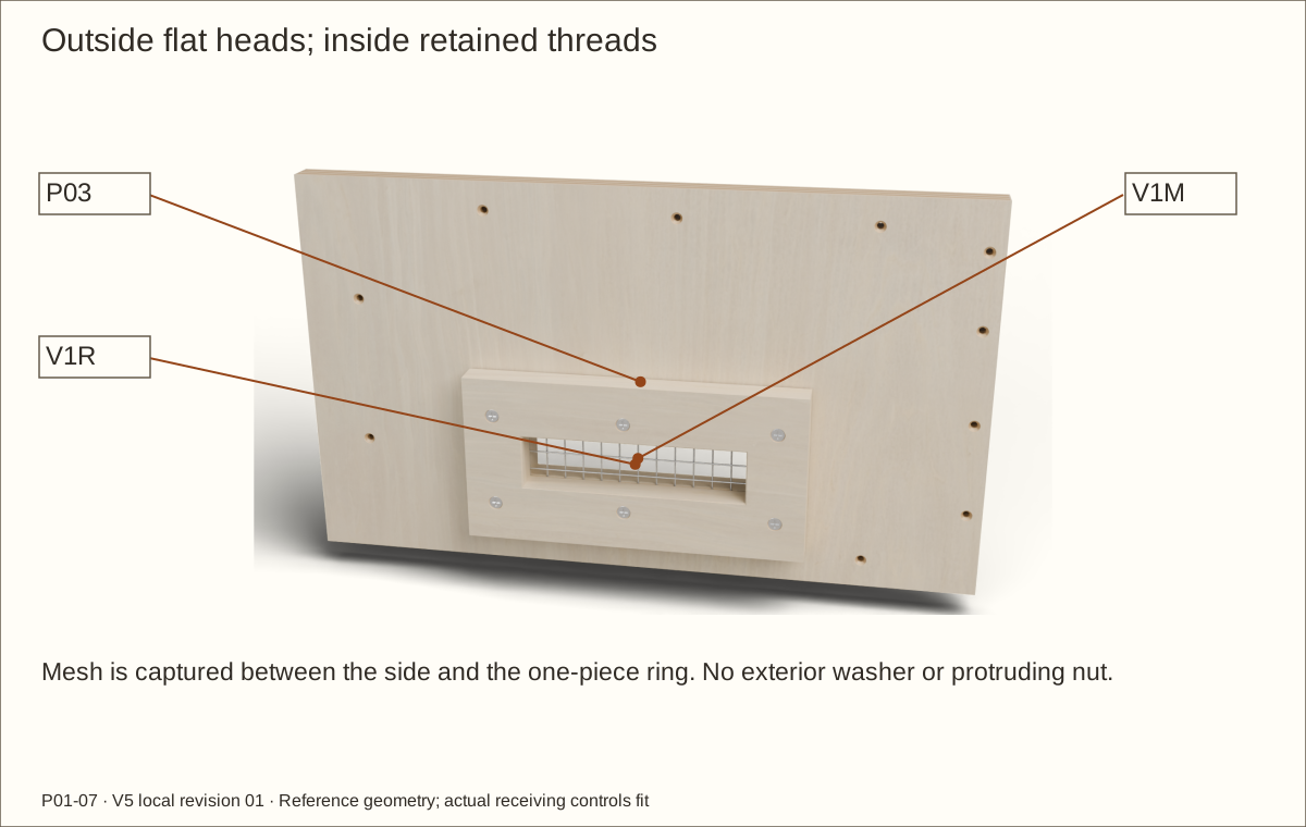
Clamp the actual roof or inlet stack and transfer all 26 screen-fixing stations through open wire cells. Preserve the ring and roof lands.
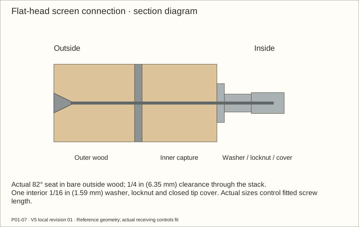
Drill the 1/4 in (6.35 mm) clearance bores, then machine a matching 82-degree seat from the exterior face. Stop at the actual head’s flush bearing; the reference maximum head envelope is 0.116 in (2.95 mm) deep.
Keep the flat head outside, with no exterior washer. Rehearse access to the interior washer, locknut and closed cover before the assembly closes that access.
Check before continuing: The actual head seats on sound bare plywood without crushing or breaking through.
Parts: Accepted material samples and the named workshop setup
Tools / setup: Tape, square, caliper, pencil and the tools named in this step
Before you begin: Do not fit a cover as a substitute for the locknut; do not use an impact driver.
Fit and trim the through screws
Purchase 2 1/2 in (63.5 mm) flat-head #10-24 screws. Assemble a sample with the actual single interior washer and nylon locknut; measure the needed fitted length.
Allow complete nylon engagement, at least two complete threads beyond the locknut after the deburred end, and at least 1/32 in (0.79 mm) unused depth in the closed cover. The model’s 2 in (50.8 mm) fitted length is only a reference.
Thread on a spare nut before cutting, clamp the screw, trim and deburr, then unwind the nut and prove both retained parts. Hold the locknut still with a thin wrench while fitting or removing the cover.
Check before continuing: Cover cannot bottom, sharp thread is enclosed and the primary locknut remains engaged.
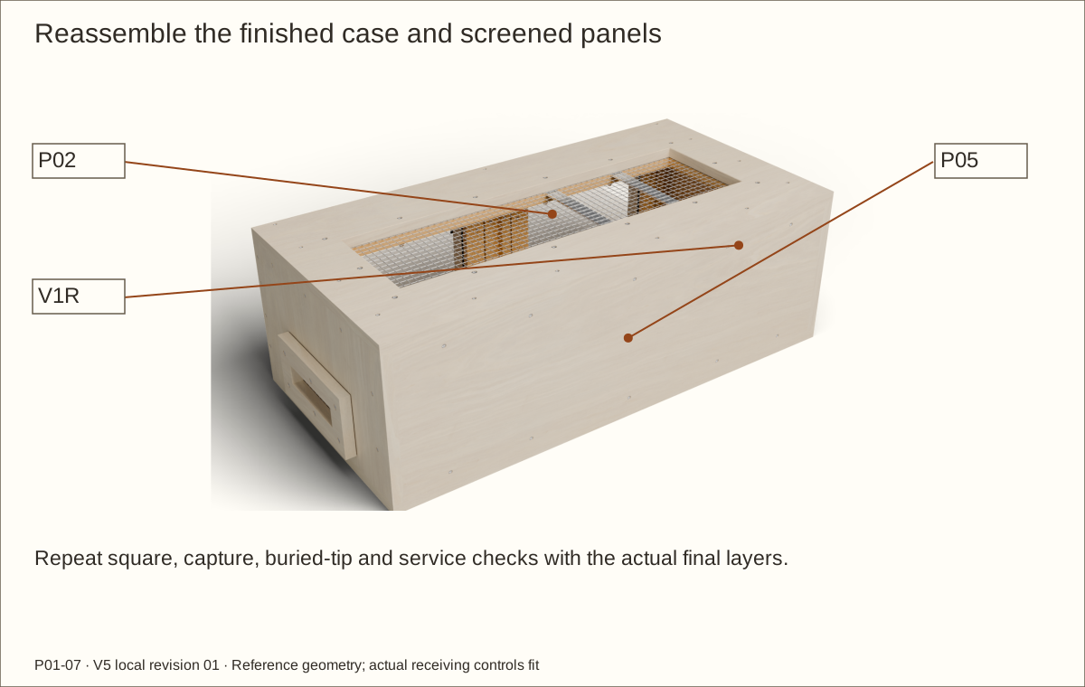
Parts: V1M · Side inlet mesh; V1R · One-piece inlet capture ring; V2M · Side inlet mesh; V2R · One-piece inlet capture ring
Tools / setup: Tape, square, caliper, pencil and the tools named in this step
Dry-fit the side screen captures
Place each side mesh against its bare mating panel and fit its labeled ring over the wire. All six exterior flat heads on each side point inward.
Fit one interior washer, locknut and closed cover per screw. Side rows are 2.72 in (69.09 mm) and 5.22 in (132.59 mm) above the floor underside. The reference 1 in (25.4 mm) washers just meet the inlet land and lower cleat; reject any actual overhang, interference or incomplete flat bearing and revise the affected stations before drilling.
Inspect the entire perimeter and both inlet openings. Record the actual wire and stack, then remove the captures for finishing.
Check before continuing: No cut wire or sharp thread remains accessible and both screens can be serviced.
Tools / setup: Tape, square, caliper, pencil and the tools named in this step
Dry-fit the roof screen and steel supports
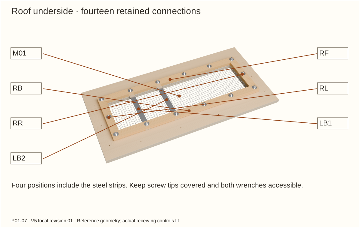
Place the removed roof top-down on padded supports. Fit M01, both steel strips and the four capture battens in their drawn order.
Fit fourteen flat-head screws from the roof exterior toward the batten underside. Their washers, locknuts and covers are all inside; four stations also capture the steel.
Check both steel seats, every covered wire edge and two-wrench access. The completed roof must still lift off as one supported service assembly.
Check before continuing: Screen, battens and both strips are retained without loose or exposed edges.
Parts: H11F · Door 1 hinge 1 fixed pin and leaf; H11M · Door 1 hinge 1 moving socket; H12F · Door 1 hinge 2 fixed pin and leaf; H12M · Door 1 hinge 2 moving socket; H21F · Door 2 hinge 1 fixed pin and leaf; H21M · Door 2 hinge 1 moving socket; H22F · Door 2 hinge 2 fixed pin and leaf; H22M · Door 2 hinge 2 moving socket
Tools / setup: Tape, square, caliper, pencil and the tools named in this step
Fit all four lift-off hinges
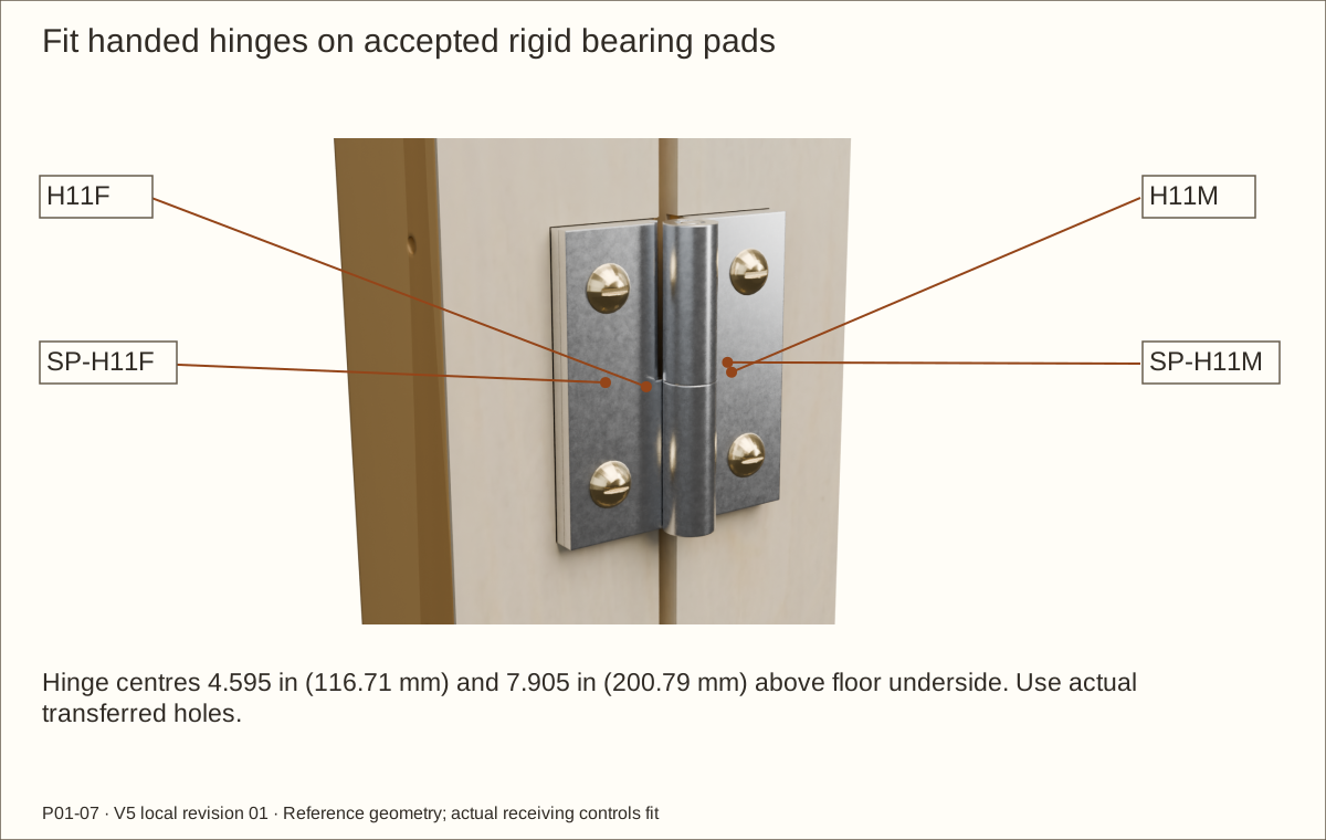
Clamp each supported leaf at the revised bare gaps. Keep hinge centres at 4.595 in (116.71 mm) and 7.905 in (200.79 mm) above the floor underside; these are absolute datums after perimeter trimming.
Fit two left-handed 1151A81 hinges and two right-handed 1151A82 hinges with fixed pins upward. Place the accepted rigid pad under every leaf on its bare wood seat; transfer holes from the received leaves.
Install sixteen S3 #8 × 1 1/4 in (31.75 mm) brass slotted round-head screws with a matched slotted driver and stopped pilots. Reference wood engagement is 1.045 in (26.54 mm) after leaf and pad. Keep pins collinear and do not enlarge purchased holes.
Check before continuing: Supported doors swing independently without binding and every point remains buried.
Tools / setup: Tape, square, caliper, pencil and the tools named in this step
Fit the two staggered keyless hasps
Set the left swivel centre 16 1/8 in (409.58 mm) from LEFT and 4 1/2 in (114.3 mm) above the floor underside. Set the right centre 19 7/8 in (504.83 mm) from LEFT and 8 in (203.2 mm) above the floor underside.
Mount each narrow hinged base on FM and its square swivel base on the moving wide latch stile. Trace complete received plates and transfer all seven holes per assembly.
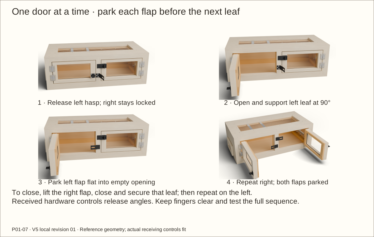
Use fourteen S4 #10 × 5/8 in (15.88 mm) flat-head screws and the accepted pilots. Release one swivel, raise its flap and open that leaf 90 degrees. Lower its flap flat into the empty opening before releasing the other hasp. Reverse these actions to close; trial every intermediate position.
Check before continuing: Both assemblies have full bearing, buried tips and independent keyless operation.
Parts: D1L · Door 1 hinge stile; D1R · Door 1 latch stile; D1B · Door 1 rail; D1T · Door 1 rail; P02 · Roof
Tools / setup: Tape, square, caliper, pencil and the tools named in this step
Before you begin: Keep the enclosure empty during this test; actual finished clearance governs.
Prove roof-on removal and pane access
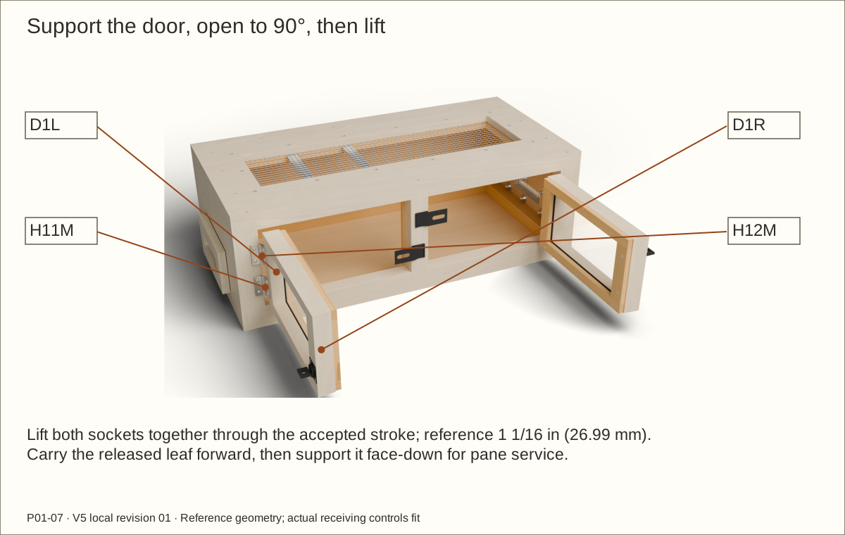
Secure the roof, release one hasp and support that leaf with a helper. Open it 90 degrees before lifting.
Lift straight up through the received release stroke, nominally 1 1/16 in (26.99 mm), keeping both sockets aligned. Carry the released door forward; never pull against one partly engaged pin.
Lay the supported door front-down on padding and confirm all rear retainers can be unscrewed. Refit both sockets completely before releasing support. Repeat on the other side.
Check before continuing: Each leaf and pane can be removed independently with the roof fitted.
Parts: P01 · Floor; P02 · Roof; P03 · Left side; P04 · Right side; D1L · Door 1 hinge stile; D2R · Door 2 hinge stile
Tools / setup: Tape, square, caliper, pencil and the tools named in this step
Dismantle and prepare wood for finishing
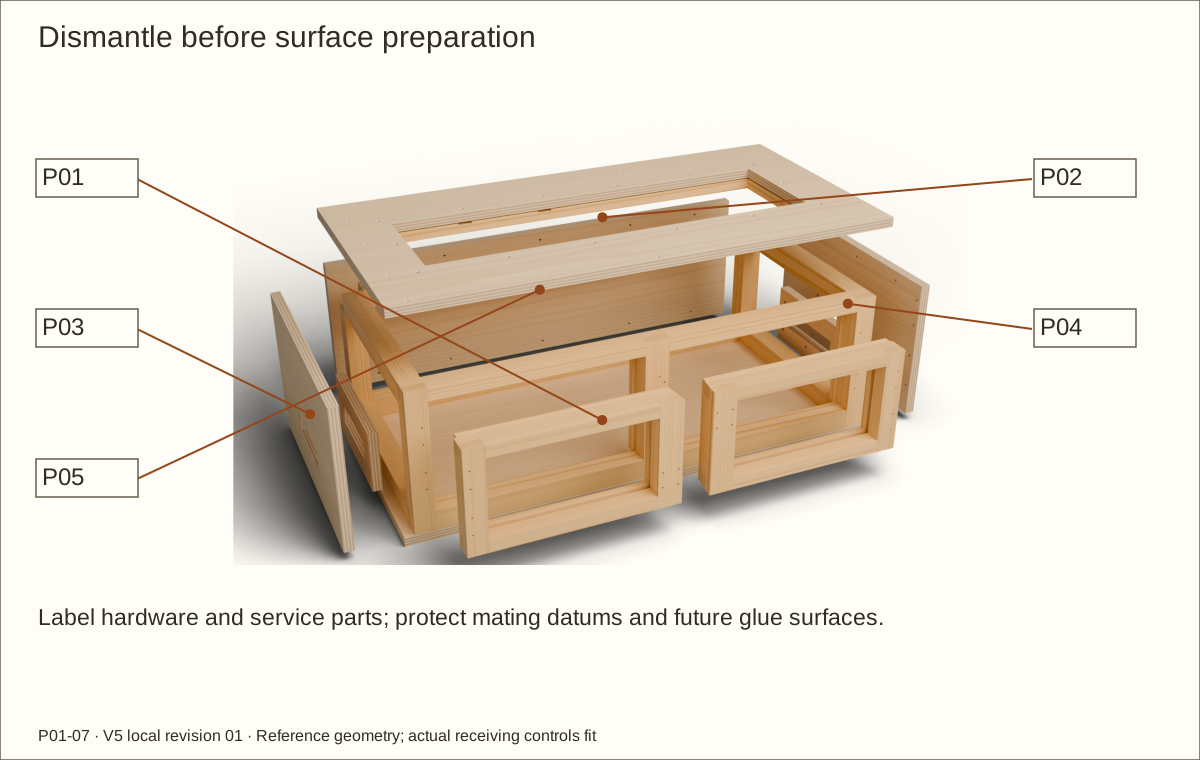
Label and remove glazing, cushions, hinges, hasps and removable captures. Preserve all service part IDs and accepted fit measurements.
Sand sound dry wood from 120 through 220 grit for the selected finish, vacuum and wipe as its instructions require. Avoid changing lap shoulders, pockets or final gaps.
Mask any still-unbonded bare glue contacts and metal bearing seats. Seal and fully cure penetrations under the accepted system before final hardware installation.
Check before continuing: The wood is clean, smooth and identified, with critical datums preserved.
Parts: Accepted material samples and the named workshop setup
Tools / setup: Tape, square, caliper, pencil and the tools named in this step
Preseal the veneer substrates
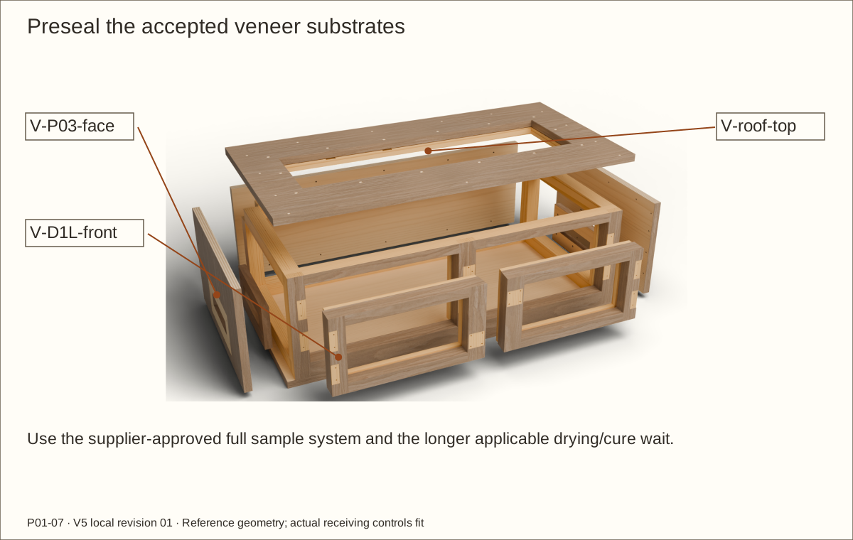
Apply only the supplier-approved sealer to the outside faces and edges scheduled for veneer. Do not coat an unfinished structural glue joint.
Follow the sealer’s complete drying/cure instructions. Oakwood’s PSA guide calls for at least 24 hours after sealing porous wood; the selected coating may require longer.
Prepare the cured surface exactly as the approved veneer sample: scuff, remove dust and avoid unapproved cleaners or residue.
Check before continuing: The accepted presealed surface is dry, sound and ready for bonding.
Required wait: Use the longer applicable sealer requirement and supplier instruction; the 24-hour veneer guidance does not replace full coating cure.
Parts: Accepted material samples and the named workshop setup
Tools / setup: Tape, square, caliper, pencil and the tools named in this step
Before you begin: Keep fingers out of the knife path and do not sand through the face veneer.
Apply the edge and reveal pieces
Match each labeled strip to the veneer schedule and grain direction. Cover exposed plywood edges, vent-ring edges, access and window reveals with separate flat pieces.
Apply pressure from the centre outward using the supplier’s stiff scraping block method, following the grain. Do not try to bend one sheet around a square corner.
Score trim cuts in several light passes on supported work, then lightly ease only the sharp veneer edge. Keep window pocket, metal seats and removable joints clear.
Check before continuing: Every specified edge is covered without overlap that consumes a fit allowance.
Parts: Accepted material samples and the named workshop setup
Tools / setup: Tape, square, caliper, pencil and the tools named in this step
Apply the exterior face veneers
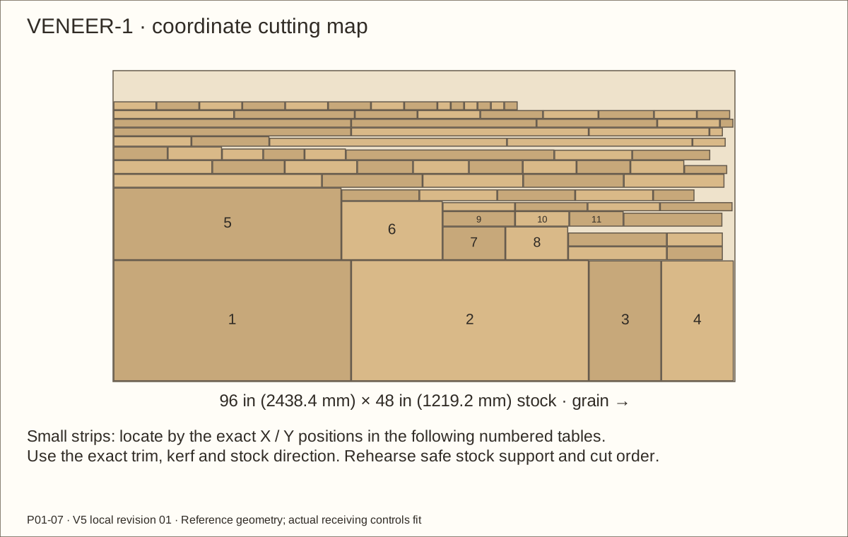
Use the full-size allocation for each outside panel, door/frame face and floor underside. Preserve the grain arrows and leave the provided trimming allowance.
Align and press each face over the already-fitted edge-piece ends. Work outward to remove trapped air and cover the complete area with the accepted scraping pressure.
Trim flush and inspect under raking light for bubbles, lifting or a changed door shape. Keep a separate seam at every service joint; do not trap the vent rings or roof under a continuous skin.
Check before continuing: Faces are flat and bonded, with consistent edge transitions and usable service seams.
Required wait: Use the supplier-confirmed bonding dwell before dependent finishing or assembly.
Tools / setup: Tape, square, caliper, pencil and the tools named in this step
Cover the roof with continuous grain
Apply the single scheduled roof face with grain along the 36 in (914.4 mm) direction. Keep its mapping and physical sheet continuous around the aperture.
Support the opening while trimming the face back to its already-banded reveals. Do not bridge or reduce the ventilation opening with a veneer membrane.
Inspect the long front edge and roof plane against a straight reference. Grain direction and lighting must not disguise a lifted edge or bow.
Check before continuing: Roof face, edges and reveals are covered and the aperture remains fully open.
45. Reopen service recesses and check the finish fit
Parts: Accepted material samples and the named workshop setup
Tools / setup: Tape, square, caliper, pencil and the tools named in this step
Before you begin: Do not bury a removable fixing under an unbroken veneer face.
Reopen service recesses and check the finish fit
Transfer the actual metal footprints and open the veneer only inside those bearing seats. Flat screw heads seat in bare wood beneath the small service recess.
Reopen every drilled hole and countersink without changing its datum or enlarging hardware holes. Refinish exposed cut wood as the accepted system requires.
Trial both fully layered doors, roof and vent rings again. Measure the finished gaps, hardware bearing and release path before applying final finish.
Check before continuing: No adhesive/veneer is trapped beneath a load-bearing plate or screw head.
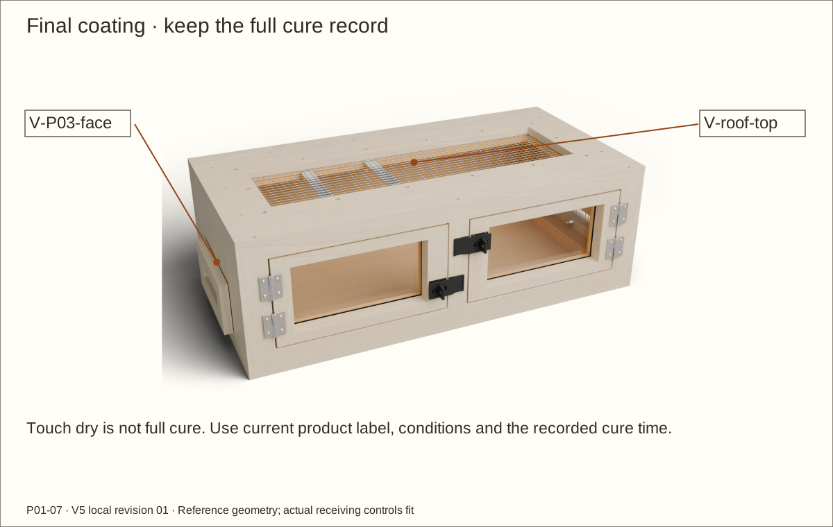
46. Apply the final coating and wait for full cure
Parts: Accepted material samples and the named workshop setup
Tools / setup: Tape, square, caliper, pencil and the tools named in this step
Before you begin: Touch-dry or absence of smell does not establish full cure or animal/contact suitability.
Apply the final coating and wait for full cure
Use the accepted Varathane Triple Thick water-based satin system for the stated indoor, non-immersed service. Stir rather than shake and apply along the grain with a synthetic brush.
Follow current conditions, nominally 60–90°F (15.6–32.2°C) and relative humidity below 85%. Reference one-coat coverage is 50 square feet (4.65 square metres) per US quart (0.946 litres); this build’s purchase allowance includes preseal, trial surfaces and extra reserve.
If another coat is needed, follow the 2-hour reference recoat interval and 220-grit preparation, and add its material quantity. Record product batch, conditions and cure start/end.
Check before continuing: The film is continuous and fully cured before hardware, glazing or occupancy.
Required wait: At 70°F (21.1°C)/50% relative humidity: 2 hours touch/recoat, 48 hours light use and 7 days full cure. Actual label and adverse conditions govern longer waits.
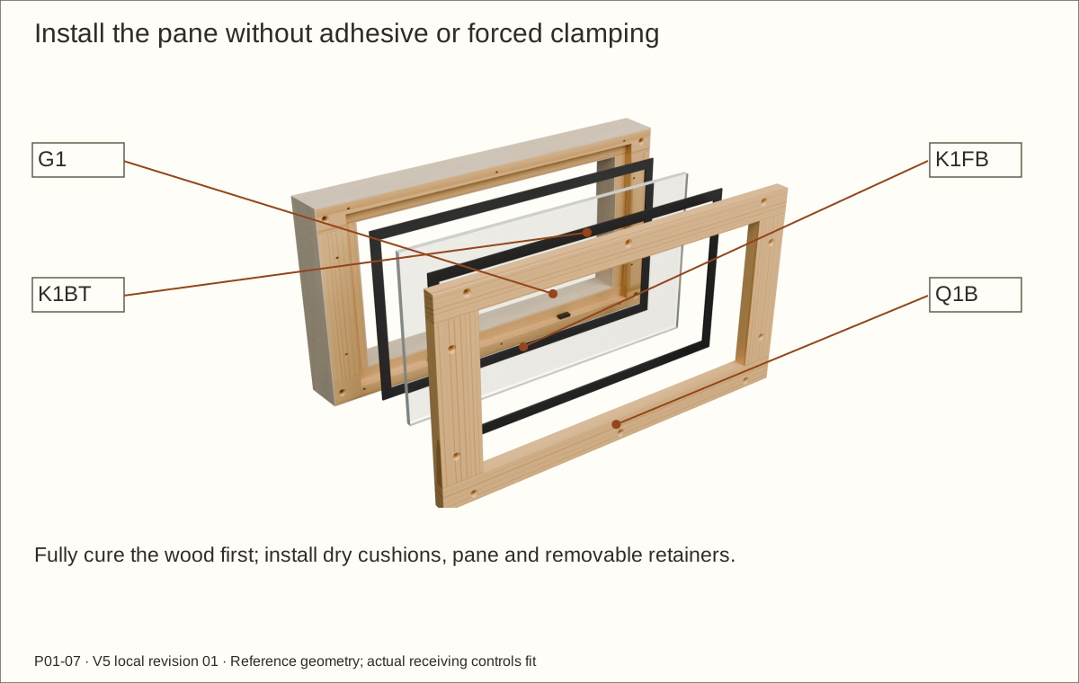
Parts: G1 · Acrylic pane 1; G2 · Acrylic pane 2; Q1B · Door 1 glazing retainer; Q1T · Door 1 glazing retainer; Q2B · Door 2 glazing retainer; Q2T · Door 2 glazing retainer
Tools / setup: Tape, square, caliper, pencil and the tools named in this step
Install the dry floating glazing
Lay each cured door front-down on padding. Fit dry front face strips in the concealed margins and two two-layer bottom setting pads at their drawn positions.
Place the clean pane without adhesive, retain the required edge spaces, then fit rear face strips and the four labeled retainers.
Use the twenty S5 #8 × 1 in (25.4 mm) retainer screws. Tighten by hand until the retainers seat on wood with light pad contact; do not bow acrylic to close a gap.
Check before continuing: Both panes are supported, captured and free to expand, with all pads concealed.
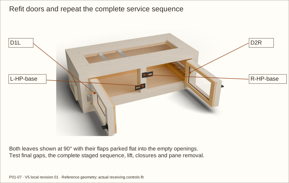
49. Refit doors and repeat the complete service check
Parts: D1L · Door 1 hinge stile; D2R · Door 2 hinge stile; H11F · Door 1 hinge 1 fixed pin and leaf; H21F · Door 2 hinge 1 fixed pin and leaf
Tools / setup: Tape, square, caliper, pencil and the tools named in this step
Refit doors and repeat the complete service check
Support each glazed door and lower both sockets fully onto the upward pins. Refit the accepted hasps on their bare bearing seats.
Open one door 90 degrees while the opposite hasp stays closed. Park the first flap flat into its empty opening; then release and open the second door and park that flap too. Reverse the order to close, lifting each flap clear before moving its door. Keep fingers outside the flap and hinge paths.
Repeat roof-on lift-off and pane-retainer access with helpers. Record actual measurements and any adjustments; do not call a rubbing or partially engaged door complete.
Check before continuing: Both leaves operate, secure and remove correctly with the final coating and glazing.
Parts: LB1 · Steel bar beneath left screen; LB2 · Steel bar beneath left screen; M01 · Roof steel mesh
Tools / setup: Tape, square, caliper, pencil and the tools named in this step
Before you begin: No habitat or equipment approval follows from this generic digital shell. If the fixture instructions cannot be met, stop and revise the equipment design.
Install and commission the reviewed equipment
Place the enclosure on its accepted support and keep it empty. Use only the reviewed fixture arrangement, attachments, guards, thermostat and cable protection.
The revised optional Fluker 27004 screen-top reference is centred 12 1/4 in (311.15 mm) from LEFT and 9 in (228.6 mm) behind FRONT over the two relocated strips. The historical proposed 2-pound (0.91 kg) limit is an untested design assumption, not a load rating.
Measure actual equipment footprint, weight and combustible clearances. Complete load/stability, heat, ventilation, moisture and species-specific containment checks before occupancy.
Check before continuing: Required supplier decisions, physical commissioning and qualified review are documented.
Parts: P02 · Roof; V1R · One-piece inlet capture ring; V2R · One-piece inlet capture ring; Q1B · Door 1 glazing retainer; H11F · Door 1 hinge 1 fixed pin and leaf
Tools / setup: Tape, square, caliper, pencil and the tools named in this step
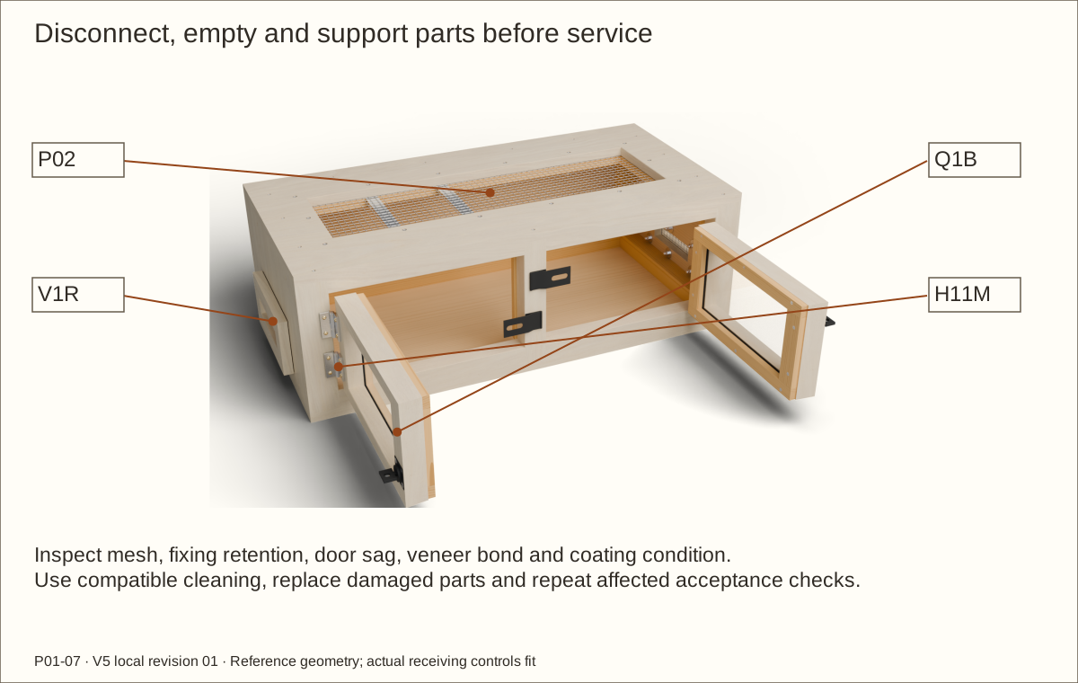
Inspect, clean and replace service parts
At the recorded inspection interval and after any leak, impact or unusual heat, check veneer lifting, coating damage, loose wood, mesh edges, door sag and fixing retention.
For OPTIX, use mild soap and lukewarm water with a soft damp non-abrasive cloth, rinse and blot dry. Avoid dry gritty cloths, abrasive cleaners and sharp scrapers. Confirm cleaner compatibility with the finish and occupants; keep wood dry and inlets clear.
Move occupants to safe temporary housing before removing a door, roof, screen or pane. Support parts, keep their IDs, replace damaged items with accepted equivalents and repeat the affected checks before recommissioning.
Check before continuing: No unresolved damage, loose hardware or exposed edge remains in use.
Choose ONE veneer species: one 48 × 96 in (1219.2 × 2438.4 mm) sheet. Trial stock is included. FINISH is a two-quart-can pack. Resolve H01–H06 before dependent work. No purchase or address-specific stock check has been made.
Published actual 0.72 in (18.29 mm) thickness. Minimum sheet dimensions 23.76 in (603.5 mm) × 47.76 in (1213.1 mm); cuts fit these minima. Indoor/dry, above ground, nonstructural. Inspect flatness and actual thickness; no aquarium shell claim.
One production board provides the six 3/4 in (19.05 mm) lamination layers, roof captures and stops. A second board is allocated to the lamination, glazing and veneer trials. Follow PINE-1 and TRIAL-PINE.
Four production boards supply the solid supports and frame members. A fifth board is reserved for the full-size frame and hardware trials. Follow SOLID-1 through SOLID-4 and TRIAL-SOLID; the trial board is not an unused spare.
Materials and hardware · continued
Choose ONE veneer species: one 48 × 96 in (1219.2 × 2438.4 mm) sheet. Trial stock is included. FINISH is a two-quart-can pack. Resolve H01–H06 before dependent work. No purchase or address-specific stock check has been made.
Four production boards supply all eight fitted retainers; no extra spare is included. Use each listed rough blank and final fitted size in POPLAR-1 through POPLAR-4. Preserve the 1/2 in (12.7 mm) thickness.
Two 12.155 in (308.74 mm) × 6.56 in (166.62 mm) panes fit the 18 in (457.2 mm) × 24 in (609.6 mm) sheet. Dry floating glazing; the actual cured pocket, measured pane and both cushions govern. Never drill or rigidly clamp the panes.
Interior zinc finish; isolate from wet exposure. Pilot/clearance holes and screw-path checks required.
Materials and hardware · continued
Choose ONE veneer species: one 48 × 96 in (1219.2 × 2438.4 mm) sheet. Trial stock is included. FINISH is a two-quart-can pack. Resolve H01–H06 before dependent work. No purchase or address-specific stock check has been made.
Apply above 47°F (8.3°C). No continuous submersion, below-waterline service or structural/load-bearing rating. Glue supplements the mechanical joints; follow actual clamping and cure requirements.
Calculated allowance 85.407 square feet (7.93 square metres), including rectangular wood faces, exterior preseal, trials and 15% extra reserve. At 50 square feet (4.65 square metres) per US quart (0.946 litres), buy 2 quarts in one two-can pack. One specified final coat; added coats need recalculation. Full cure: 7 days at 70°F (21.1°C) and 50% relative humidity; adverse conditions require longer. Indoor, non-immersed service; H05 suitability remains open.
Materials and hardware · continued
Choose ONE veneer species: one 48 × 96 in (1219.2 × 2438.4 mm) sheet. Trial stock is included. FINISH is a two-quart-can pack. Resolve H01–H06 before dependent work. No purchase or address-specific stock check has been made.
Cut 16 face strips and eight setting-pad layers. Use dry, unbonded solid neoprene; no assumed compression percentage. The actual cured stack trial governs pocket fit.
One 24 in (609.6 mm) × 60 in (1524 mm) roll supplies the 30 in (762 mm) × 10 in (254 mm) roof piece and two 8 in (203.2 mm) × 3 1/2 in (88.9 mm) side pieces. Measure actual cell spacing, wire diameter and welded crossings. Reference geometry is not a containment approval; the supplier excludes pet birds.
82-degree head, 0.333 in (8.46 mm) – 0.362 in (9.19 mm) diameter, 0.116 in (2.95 mm) head-height envelope, 0.19 in (4.83 mm) shank. Purchase length 2 1/2 in (63.5 mm); fit/trim to received inside stack. Reference fitted length 2 in (50.8 mm) is not a universal cut length. No outside washer.
Materials and hardware · continued
Choose ONE veneer species: one 48 × 96 in (1219.2 × 2438.4 mm) sheet. Trial stock is included. FINISH is a two-quart-can pack. Resolve H01–H06 before dependent work. No purchase or address-specific stock check has been made.
One closed cap per station, beyond the locking nut. Prove non-bottoming and cover every thread end.
Materials and hardware · continued
Choose ONE veneer species: one 48 × 96 in (1219.2 × 2438.4 mm) sheet. Trial stock is included. FINISH is a two-quart-can pack. Resolve H01–H06 before dependent work. No purchase or address-specific stock check has been made.
Product
Model and quantities
Fit / purchase condition
HASP · National Hardware black swivel-staple safety hasp, 3-1/4 inch Direct product listing
Seven #10 × 5/8 in (15.88 mm) screws per complete hasp. Transfer actual holes and trial head seating; verify the stopped tips remain in their named solid receivers, clear of the rear glazing pocket.
Cut two 11 in (279.4 mm) solid steel strips; retain 1 in (25.4 mm) width and 1/8 in (3.18 mm) thickness. Drill 1/4 in (6.35 mm) holes, centred across width, 3/4 in (19.05 mm) from each end. Fit to the actual roof stack; no fixture load rating.
Materials and hardware · continued
Choose ONE veneer species: one 48 × 96 in (1219.2 × 2438.4 mm) sheet. Trial stock is included. FINISH is a two-quart-can pack. Resolve H01–H06 before dependent work. No purchase or address-specific stock check has been made.
Optional example only. Reference centre is 12 1/4 in (311.15 mm) from LEFT and 9 in (228.6 mm) behind FRONT over the two shifted strips. Received footprint, support contact, attachment, weight and thermal clearances require acceptance. Do not infer fit from a nominal product diameter or the render.
HINGE-L · McMaster304 stainless surface lift-off hinge, left hand Direct product listing
Fixed pin points upward. Actual CAD proves source installation samples; no published weight capacity and no physical load qualification. Use actual hinge to transfer holes.
HINGE-R · McMaster304 stainless surface lift-off hinge, right hand Direct product listing
Fixed pin points upward. Actual CAD proves source installation samples; no published weight capacity and no physical load qualification. Use actual hinge to transfer holes.
Materials and hardware · continued
Choose ONE veneer species: one 48 × 96 in (1219.2 × 2438.4 mm) sheet. Trial stock is included. FINISH is a two-quart-can pack. Resolve H01–H06 before dependent work. No purchase or address-specific stock check has been made.
Sixteen hinge screws. Flat bearing in noncountersunk leaf holes; slotted driver. Reference 1.045 in (26.54 mm) wood engagement after the 0.08 in (2.03 mm) leaf and 1/8 in (3.18 mm) pad; actual geometry and strength require H02 acceptance.
Twenty glazing-retainer positions. Match received root, head and stopped pilot; minimum 1/16 in (1.59 mm) rear wood cover. Required thread engagement and service exposure still need physical acceptance.
Eight rigid pads, each 2 in (50.8 mm) × 23/32 in (18.26 mm) × 1/8 in (3.18 mm), plus two trial pads. Transfer actual handed hinge holes; both leaves use equal pads, at least 7/64 in (2.78 mm) thick. Custom mounting acceptance remains H02.
Materials and hardware · continued
Choose ONE veneer species: one 48 × 96 in (1219.2 × 2438.4 mm) sheet. Trial stock is included. FINISH is a two-quart-can pack. Resolve H01–H06 before dependent work. No purchase or address-specific stock check has been made.
Product
Model and quantities
Fit / purchase condition
VENEER-maple · Optional maple veneer, 48 × 96 inches, selected 3M PSA backing Direct product listing
maple-veneer-flat-cut Needed 1 + 0 trial units; 1 per package; buy 1 package(s) Choose one veneer species
Same maximum complete 0.046 in (1.17 mm) layer allowance for all choices; supplier balance/bond/finish approval and full-size trial required. Separate edge pieces; do not bend around square corners.
VENEER-oak · Optional white oak veneer, 48 × 96 inches, selected 3M PSA backing Direct product listing
oak-veneer-white-flat-cut Needed 1 + 0 trial units; 1 per package; buy 1 package(s) Choose one veneer species
Same maximum complete 0.046 in (1.17 mm) layer allowance for all choices; supplier balance/bond/finish approval and full-size trial required. Separate edge pieces; do not bend around square corners.
walnut-veneer-flat-cut Needed 1 + 0 trial units; 1 per package; buy 1 package(s) Choose one veneer species
Same maximum complete 0.046 in (1.17 mm) layer allowance for all choices; supplier balance/bond/finish approval and full-size trial required. Separate edge pieces; do not bend around square corners.
Cut list
Cut list
One of each ID. Length follows allocated grain. Rough blanks retain fitting allowance; finished sizes are reference geometry. V-parts represent the complete cured veneer stack. Laminated member layers are listed individually in the stock layouts.
Part
Rough length × width
Finished length × width × thickness
P01 · Floor
36 1/8 in (917.58 mm) × 18 1/8 in (460.38 mm)
36 in (914.4 mm) × 18 in (457.2 mm) × 0.72 in (18.29 mm)
P02 · Roof
36 1/8 in (917.58 mm) × 18 1/8 in (460.38 mm)
36 in (914.4 mm) × 18 in (457.2 mm) × 0.72 in (18.29 mm)
P03 · Left side
10.685 in (271.4 mm) × 18 1/8 in (460.38 mm)
10.56 in (268.22 mm) × 18 in (457.2 mm) × 0.72 in (18.29 mm)
P04 · Right side
10.685 in (271.4 mm) × 18 1/8 in (460.38 mm)
10.56 in (268.22 mm) × 18 in (457.2 mm) × 0.72 in (18.29 mm)
P05 · Back
34.685 in (881 mm) × 10.685 in (271.4 mm)
34.56 in (877.82 mm) × 10.56 in (268.22 mm) × 0.72 in (18.29 mm)
CLB · Solid side B cleat
14.405 in (365.89 mm) × 1 1/2 in (38.1 mm)
14.28 in (362.71 mm) × 1 1/2 in (38.1 mm) × 1 1/2 in (38.1 mm)
CLT · Solid side T cleat
14.405 in (365.89 mm) × 1 1/2 in (38.1 mm)
14.28 in (362.71 mm) × 1 1/2 in (38.1 mm) × 1 1/2 in (38.1 mm)
CLV · Solid rear upright cleat
7.685 in (195.2 mm) × 1 1/2 in (38.1 mm)
7.56 in (192.02 mm) × 1 1/2 in (38.1 mm) × 1 1/2 in (38.1 mm)
CRB · Solid side B cleat
14.405 in (365.89 mm) × 1 1/2 in (38.1 mm)
14.28 in (362.71 mm) × 1 1/2 in (38.1 mm) × 1 1/2 in (38.1 mm)
CRT · Solid side T cleat
14.405 in (365.89 mm) × 1 1/2 in (38.1 mm)
14.28 in (362.71 mm) × 1 1/2 in (38.1 mm) × 1 1/2 in (38.1 mm)
Cut list · continued
One of each ID. Length follows allocated grain. Rough blanks retain fitting allowance; finished sizes are reference geometry. V-parts represent the complete cured veneer stack. Laminated member layers are listed individually in the stock layouts.
Part
Rough length × width
Finished length × width × thickness
CRV · Solid rear upright cleat
7.685 in (195.2 mm) × 1 1/2 in (38.1 mm)
7.56 in (192.02 mm) × 1 1/2 in (38.1 mm) × 1 1/2 in (38.1 mm)
CBB · Solid back horizontal cleat
31.685 in (804.8 mm) × 1 1/2 in (38.1 mm)
31.56 in (801.62 mm) × 1 1/2 in (38.1 mm) × 1 1/2 in (38.1 mm)
CBT · Solid back horizontal cleat
31.685 in (804.8 mm) × 1 1/2 in (38.1 mm)
31.56 in (801.62 mm) × 1 1/2 in (38.1 mm) × 1 1/2 in (38.1 mm)
ST0 · Vertical door stop
8.185 in (207.9 mm) × 3/4 in (19.05 mm)
8.06 in (204.72 mm) × 3/4 in (19.05 mm) × 1/2 in (12.7 mm)
ST1 · Vertical door stop
8.185 in (207.9 mm) × 3/4 in (19.05 mm)
8.06 in (204.72 mm) × 3/4 in (19.05 mm) × 1/2 in (12.7 mm)
ST2 · Vertical door stop
8.185 in (207.9 mm) × 3/4 in (19.05 mm)
8.06 in (204.72 mm) × 3/4 in (19.05 mm) × 1/2 in (12.7 mm)
ST3 · Vertical door stop
8.185 in (207.9 mm) × 3/4 in (19.05 mm)
8.06 in (204.72 mm) × 3/4 in (19.05 mm) × 1/2 in (12.7 mm)
M01 · Roof steel mesh
30 in (762 mm) × 10 in (254 mm)
30 in (762 mm) × 10 in (254 mm) × 0.082 in (2.08 mm)
RF · Roof capture batten
31 1/8 in (790.58 mm) × 1 1/2 in (38.1 mm)
31 in (787.4 mm) × 1 1/2 in (38.1 mm) × 3/4 in (19.05 mm)
RB · Roof capture batten
31 1/8 in (790.58 mm) × 1 1/2 in (38.1 mm)
31 in (787.4 mm) × 1 1/2 in (38.1 mm) × 3/4 in (19.05 mm)
Cut list · continued
One of each ID. Length follows allocated grain. Rough blanks retain fitting allowance; finished sizes are reference geometry. V-parts represent the complete cured veneer stack. Laminated member layers are listed individually in the stock layouts.
Part
Rough length × width
Finished length × width × thickness
RL · Roof capture batten
8 1/8 in (206.38 mm) × 1 1/2 in (38.1 mm)
8 in (203.2 mm) × 1 1/2 in (38.1 mm) × 3/4 in (19.05 mm)
RR · Roof capture batten
8 1/8 in (206.38 mm) × 1 1/2 in (38.1 mm)
8 in (203.2 mm) × 1 1/2 in (38.1 mm) × 3/4 in (19.05 mm)
V1M · Side inlet mesh
8 in (203.2 mm) × 3 1/2 in (88.9 mm)
8 in (203.2 mm) × 3 1/2 in (88.9 mm) × 0.082 in (2.08 mm)
V1R · One-piece inlet capture ring
9 1/8 in (231.78 mm) × 4 5/8 in (117.48 mm)
9 in (228.6 mm) × 4 1/2 in (114.3 mm) × 0.72 in (18.29 mm)
V2M · Side inlet mesh
8 in (203.2 mm) × 3 1/2 in (88.9 mm)
8 in (203.2 mm) × 3 1/2 in (88.9 mm) × 0.082 in (2.08 mm)
V2R · One-piece inlet capture ring
9 1/8 in (231.78 mm) × 4 5/8 in (117.48 mm)
9 in (228.6 mm) × 4 1/2 in (114.3 mm) × 0.72 in (18.29 mm)
FL · Fixed L stile
10.685 in (271.4 mm) × 1 1/2 in (38.1 mm)
10.56 in (268.22 mm) × 1 1/2 in (38.1 mm) × 1 1/2 in (38.1 mm)
FM · Fixed centre stile
10.685 in (271.4 mm) × 1 3/4 in (44.45 mm)
10.56 in (268.22 mm) × 1 3/4 in (44.45 mm) × 1 1/2 in (38.1 mm)
FR · Fixed R stile
10.685 in (271.4 mm) × 1 1/2 in (38.1 mm)
10.56 in (268.22 mm) × 1 1/2 in (38.1 mm) × 1 1/2 in (38.1 mm)
FB · Fixed sill
34.685 in (881 mm) × 1 1/2 in (38.1 mm)
34.56 in (877.82 mm) × 1 1/2 in (38.1 mm) × 1 1/2 in (38.1 mm)
Cut list · continued
One of each ID. Length follows allocated grain. Rough blanks retain fitting allowance; finished sizes are reference geometry. V-parts represent the complete cured veneer stack. Laminated member layers are listed individually in the stock layouts.
Part
Rough length × width
Finished length × width × thickness
FT · Fixed header
34.685 in (881 mm) × 1 in (25.4 mm)
34.56 in (877.82 mm) × 1 in (25.4 mm) × 1 1/2 in (38.1 mm)
D1L · Door 1 hinge stile
7.81 in (198.37 mm) × 1 7/16 in (36.51 mm)
7.685 in (195.2 mm) × 1 7/16 in (36.51 mm) × 1 1/2 in (38.1 mm)
D1R · Door 1 latch stile
7.81 in (198.37 mm) × 1 23/32 in (43.66 mm)
7.685 in (195.2 mm) × 1 23/32 in (43.66 mm) × 1 1/2 in (38.1 mm)
D1B · Door 1 rail
14.68625 in (373.03 mm) × 15/16 in (23.81 mm)
14.56125 in (369.86 mm) × 15/16 in (23.81 mm) × 1 1/2 in (38.1 mm)
D1T · Door 1 rail
14.68625 in (373.03 mm) × 15/16 in (23.81 mm)
14.56125 in (369.86 mm) × 15/16 in (23.81 mm) × 1 1/2 in (38.1 mm)
G1 · Acrylic pane 1
12.155 in (308.74 mm) × 6.56 in (166.62 mm)
12.155 in (308.74 mm) × 6.56 in (166.62 mm) × 0.22 in (5.59 mm)
Q1B · Door 1 glazing retainer
14.28 in (362.71 mm) × 15/16 in (23.81 mm)
14.155 in (359.54 mm) × 15/16 in (23.81 mm) × 1/2 in (12.7 mm)
Q1T · Door 1 glazing retainer
14.28 in (362.71 mm) × 15/16 in (23.81 mm)
14.155 in (359.54 mm) × 15/16 in (23.81 mm) × 1/2 in (12.7 mm)
Q1L · Door 1 glazing retainer
5.935 in (150.75 mm) × 1 1/4 in (31.75 mm)
5.81 in (147.57 mm) × 1 1/4 in (31.75 mm) × 1/2 in (12.7 mm)
Q1R · Door 1 glazing retainer
5.935 in (150.75 mm) × 1 1/2 in (38.1 mm)
5.81 in (147.57 mm) × 1 1/2 in (38.1 mm) × 1/2 in (12.7 mm)
Cut list · continued
One of each ID. Length follows allocated grain. Rough blanks retain fitting allowance; finished sizes are reference geometry. V-parts represent the complete cured veneer stack. Laminated member layers are listed individually in the stock layouts.
Part
Rough length × width
Finished length × width × thickness
K1FB · Door 1 dry neoprene cushion
12.155 in (308.74 mm) × 3/8 in (9.53 mm)
12.155 in (308.74 mm) × 3/8 in (9.53 mm) × 1/16 in (1.59 mm)
K1FT · Door 1 dry neoprene cushion
12.155 in (308.74 mm) × 3/8 in (9.53 mm)
12.155 in (308.74 mm) × 3/8 in (9.53 mm) × 1/16 in (1.59 mm)
K1FL · Door 1 dry neoprene cushion
5.81 in (147.57 mm) × 3/8 in (9.53 mm)
5.81 in (147.57 mm) × 3/8 in (9.53 mm) × 1/16 in (1.59 mm)
K1FR · Door 1 dry neoprene cushion
5.81 in (147.57 mm) × 3/8 in (9.53 mm)
5.81 in (147.57 mm) × 3/8 in (9.53 mm) × 1/16 in (1.59 mm)
K1BB · Door 1 dry neoprene cushion
12.155 in (308.74 mm) × 3/8 in (9.53 mm)
12.155 in (308.74 mm) × 3/8 in (9.53 mm) × 1/16 in (1.59 mm)
K1BT · Door 1 dry neoprene cushion
12.155 in (308.74 mm) × 3/8 in (9.53 mm)
12.155 in (308.74 mm) × 3/8 in (9.53 mm) × 1/16 in (1.59 mm)
K1BL · Door 1 dry neoprene cushion
5.81 in (147.57 mm) × 3/8 in (9.53 mm)
5.81 in (147.57 mm) × 3/8 in (9.53 mm) × 1/16 in (1.59 mm)
K1BR · Door 1 dry neoprene cushion
5.81 in (147.57 mm) × 3/8 in (9.53 mm)
5.81 in (147.57 mm) × 3/8 in (9.53 mm) × 1/16 in (1.59 mm)
K1S10 · Door 1 bottom setting-pad layer
1/2 in (12.7 mm) × 0.22 in (5.59 mm)
1/2 in (12.7 mm) × 0.22 in (5.59 mm) × 1/16 in (1.59 mm)
K1S11 · Door 1 bottom setting-pad layer
1/2 in (12.7 mm) × 0.22 in (5.59 mm)
1/2 in (12.7 mm) × 0.22 in (5.59 mm) × 1/16 in (1.59 mm)
Cut list · continued
One of each ID. Length follows allocated grain. Rough blanks retain fitting allowance; finished sizes are reference geometry. V-parts represent the complete cured veneer stack. Laminated member layers are listed individually in the stock layouts.
Part
Rough length × width
Finished length × width × thickness
K1S20 · Door 1 bottom setting-pad layer
1/2 in (12.7 mm) × 0.22 in (5.59 mm)
1/2 in (12.7 mm) × 0.22 in (5.59 mm) × 1/16 in (1.59 mm)
K1S21 · Door 1 bottom setting-pad layer
1/2 in (12.7 mm) × 0.22 in (5.59 mm)
1/2 in (12.7 mm) × 0.22 in (5.59 mm) × 1/16 in (1.59 mm)
D2L · Door 2 latch stile
7.81 in (198.37 mm) × 1 23/32 in (43.66 mm)
7.685 in (195.2 mm) × 1 23/32 in (43.66 mm) × 1 1/2 in (38.1 mm)
D2R · Door 2 hinge stile
7.81 in (198.37 mm) × 1 7/16 in (36.51 mm)
7.685 in (195.2 mm) × 1 7/16 in (36.51 mm) × 1 1/2 in (38.1 mm)
D2B · Door 2 rail
14.68625 in (373.03 mm) × 15/16 in (23.81 mm)
14.56125 in (369.86 mm) × 15/16 in (23.81 mm) × 1 1/2 in (38.1 mm)
D2T · Door 2 rail
14.68625 in (373.03 mm) × 15/16 in (23.81 mm)
14.56125 in (369.86 mm) × 15/16 in (23.81 mm) × 1 1/2 in (38.1 mm)
G2 · Acrylic pane 2
12.155 in (308.74 mm) × 6.56 in (166.62 mm)
12.155 in (308.74 mm) × 6.56 in (166.62 mm) × 0.22 in (5.59 mm)
Q2B · Door 2 glazing retainer
14.28 in (362.71 mm) × 15/16 in (23.81 mm)
14.155 in (359.54 mm) × 15/16 in (23.81 mm) × 1/2 in (12.7 mm)
Q2T · Door 2 glazing retainer
14.28 in (362.71 mm) × 15/16 in (23.81 mm)
14.155 in (359.54 mm) × 15/16 in (23.81 mm) × 1/2 in (12.7 mm)
Q2L · Door 2 glazing retainer
5.935 in (150.75 mm) × 1 1/2 in (38.1 mm)
5.81 in (147.57 mm) × 1 1/2 in (38.1 mm) × 1/2 in (12.7 mm)
Cut list · continued
One of each ID. Length follows allocated grain. Rough blanks retain fitting allowance; finished sizes are reference geometry. V-parts represent the complete cured veneer stack. Laminated member layers are listed individually in the stock layouts.
Part
Rough length × width
Finished length × width × thickness
Q2R · Door 2 glazing retainer
5.935 in (150.75 mm) × 1 1/4 in (31.75 mm)
5.81 in (147.57 mm) × 1 1/4 in (31.75 mm) × 1/2 in (12.7 mm)
K2FB · Door 2 dry neoprene cushion
12.155 in (308.74 mm) × 3/8 in (9.53 mm)
12.155 in (308.74 mm) × 3/8 in (9.53 mm) × 1/16 in (1.59 mm)
K2FT · Door 2 dry neoprene cushion
12.155 in (308.74 mm) × 3/8 in (9.53 mm)
12.155 in (308.74 mm) × 3/8 in (9.53 mm) × 1/16 in (1.59 mm)
K2FL · Door 2 dry neoprene cushion
5.81 in (147.57 mm) × 3/8 in (9.53 mm)
5.81 in (147.57 mm) × 3/8 in (9.53 mm) × 1/16 in (1.59 mm)
K2FR · Door 2 dry neoprene cushion
5.81 in (147.57 mm) × 3/8 in (9.53 mm)
5.81 in (147.57 mm) × 3/8 in (9.53 mm) × 1/16 in (1.59 mm)
K2BB · Door 2 dry neoprene cushion
12.155 in (308.74 mm) × 3/8 in (9.53 mm)
12.155 in (308.74 mm) × 3/8 in (9.53 mm) × 1/16 in (1.59 mm)
K2BT · Door 2 dry neoprene cushion
12.155 in (308.74 mm) × 3/8 in (9.53 mm)
12.155 in (308.74 mm) × 3/8 in (9.53 mm) × 1/16 in (1.59 mm)
K2BL · Door 2 dry neoprene cushion
5.81 in (147.57 mm) × 3/8 in (9.53 mm)
5.81 in (147.57 mm) × 3/8 in (9.53 mm) × 1/16 in (1.59 mm)
K2BR · Door 2 dry neoprene cushion
5.81 in (147.57 mm) × 3/8 in (9.53 mm)
5.81 in (147.57 mm) × 3/8 in (9.53 mm) × 1/16 in (1.59 mm)
K2S10 · Door 2 bottom setting-pad layer
1/2 in (12.7 mm) × 0.22 in (5.59 mm)
1/2 in (12.7 mm) × 0.22 in (5.59 mm) × 1/16 in (1.59 mm)
Cut list · continued
One of each ID. Length follows allocated grain. Rough blanks retain fitting allowance; finished sizes are reference geometry. V-parts represent the complete cured veneer stack. Laminated member layers are listed individually in the stock layouts.
Part
Rough length × width
Finished length × width × thickness
K2S11 · Door 2 bottom setting-pad layer
1/2 in (12.7 mm) × 0.22 in (5.59 mm)
1/2 in (12.7 mm) × 0.22 in (5.59 mm) × 1/16 in (1.59 mm)
K2S20 · Door 2 bottom setting-pad layer
1/2 in (12.7 mm) × 0.22 in (5.59 mm)
1/2 in (12.7 mm) × 0.22 in (5.59 mm) × 1/16 in (1.59 mm)
K2S21 · Door 2 bottom setting-pad layer
1/2 in (12.7 mm) × 0.22 in (5.59 mm)
1/2 in (12.7 mm) × 0.22 in (5.59 mm) × 1/16 in (1.59 mm)
LB1 · Steel bar beneath left screen
11 in (279.4 mm) × 1 in (25.4 mm)
11 in (279.4 mm) × 1 in (25.4 mm) × 1/8 in (3.18 mm)
LB2 · Steel bar beneath left screen
11 in (279.4 mm) × 1 in (25.4 mm)
11 in (279.4 mm) × 1 in (25.4 mm) × 1/8 in (3.18 mm)
SP-H11M · Rigid hinge bearing pad H11M
2 in (50.8 mm) × 23/32 in (18.26 mm)
2 in (50.8 mm) × 23/32 in (18.26 mm) × 1/8 in (3.18 mm)
SP-H11F · Rigid hinge bearing pad H11F
2 in (50.8 mm) × 23/32 in (18.26 mm)
2 in (50.8 mm) × 23/32 in (18.26 mm) × 1/8 in (3.18 mm)
SP-H12M · Rigid hinge bearing pad H12M
2 in (50.8 mm) × 23/32 in (18.26 mm)
2 in (50.8 mm) × 23/32 in (18.26 mm) × 1/8 in (3.18 mm)
SP-H12F · Rigid hinge bearing pad H12F
2 in (50.8 mm) × 23/32 in (18.26 mm)
2 in (50.8 mm) × 23/32 in (18.26 mm) × 1/8 in (3.18 mm)
SP-H21F · Rigid hinge bearing pad H21F
2 in (50.8 mm) × 23/32 in (18.26 mm)
2 in (50.8 mm) × 23/32 in (18.26 mm) × 1/8 in (3.18 mm)
Cut list · continued
One of each ID. Length follows allocated grain. Rough blanks retain fitting allowance; finished sizes are reference geometry. V-parts represent the complete cured veneer stack. Laminated member layers are listed individually in the stock layouts.
Part
Rough length × width
Finished length × width × thickness
SP-H21M · Rigid hinge bearing pad H21M
2 in (50.8 mm) × 23/32 in (18.26 mm)
2 in (50.8 mm) × 23/32 in (18.26 mm) × 1/8 in (3.18 mm)
SP-H22F · Rigid hinge bearing pad H22F
2 in (50.8 mm) × 23/32 in (18.26 mm)
2 in (50.8 mm) × 23/32 in (18.26 mm) × 1/8 in (3.18 mm)
SP-H22M · Rigid hinge bearing pad H22M
2 in (50.8 mm) × 23/32 in (18.26 mm)
2 in (50.8 mm) × 23/32 in (18.26 mm) × 1/8 in (3.18 mm)
V-floor-under · Exterior veneer · floor-under
36.561 in (928.65 mm) × 18.561 in (471.45 mm)
36.061 in (915.95 mm) × 18.061 in (458.75 mm) × 0.0305 in (0.77 mm)
V-roof-top · Exterior veneer · roof-top
36.561 in (928.65 mm) × 18.561 in (471.45 mm)
36.061 in (915.95 mm) × 18.061 in (458.75 mm) × 0.0305 in (0.77 mm)
V-P01-front · Exterior veneer · P01-front
36.561 in (928.65 mm) × 1.22 in (30.99 mm)
36.061 in (915.95 mm) × 0.72 in (18.29 mm) × 0.0305 in (0.77 mm)
V-P01-back · Exterior veneer · P01-back
36.561 in (928.65 mm) × 1.22 in (30.99 mm)
36.061 in (915.95 mm) × 0.72 in (18.29 mm) × 0.0305 in (0.77 mm)
V-P01-left · Exterior veneer · P01-left
18 1/2 in (469.9 mm) × 1.22 in (30.99 mm)
18 in (457.2 mm) × 0.72 in (18.29 mm) × 0.0305 in (0.77 mm)
V-P01-right · Exterior veneer · P01-right
18 1/2 in (469.9 mm) × 1.22 in (30.99 mm)
18 in (457.2 mm) × 0.72 in (18.29 mm) × 0.0305 in (0.77 mm)
V-P02-front · Exterior veneer · P02-front
36.561 in (928.65 mm) × 1.22 in (30.99 mm)
36.061 in (915.95 mm) × 0.72 in (18.29 mm) × 0.0305 in (0.77 mm)
Cut list · continued
One of each ID. Length follows allocated grain. Rough blanks retain fitting allowance; finished sizes are reference geometry. V-parts represent the complete cured veneer stack. Laminated member layers are listed individually in the stock layouts.
Part
Rough length × width
Finished length × width × thickness
V-P02-back · Exterior veneer · P02-back
36.561 in (928.65 mm) × 1.22 in (30.99 mm)
36.061 in (915.95 mm) × 0.72 in (18.29 mm) × 0.0305 in (0.77 mm)
V-P02-left · Exterior veneer · P02-left
18 1/2 in (469.9 mm) × 1.22 in (30.99 mm)
18 in (457.2 mm) × 0.72 in (18.29 mm) × 0.0305 in (0.77 mm)
V-P02-right · Exterior veneer · P02-right
18 1/2 in (469.9 mm) × 1.22 in (30.99 mm)
18 in (457.2 mm) × 0.72 in (18.29 mm) × 0.0305 in (0.77 mm)
V-P03-face · Exterior veneer · P03-face
11.06 in (280.92 mm) × 18 1/2 in (469.9 mm)
10.56 in (268.22 mm) × 18 in (457.2 mm) × 0.0305 in (0.77 mm)
V-P03-front · Exterior veneer · P03-front
11.06 in (280.92 mm) × 1.2505 in (31.76 mm)
10.56 in (268.22 mm) × 0.7505 in (19.06 mm) × 0.0305 in (0.77 mm)
V-P03-back · Exterior veneer · P03-back
11.06 in (280.92 mm) × 1.2505 in (31.76 mm)
10.56 in (268.22 mm) × 0.7505 in (19.06 mm) × 0.0305 in (0.77 mm)
V-P03-vent-near · Exterior veneer · P03-vent-near
1.939 in (49.25 mm) × 1.22 in (30.99 mm)
1.439 in (36.55 mm) × 0.72 in (18.29 mm) × 0.0305 in (0.77 mm)
V-P03-vent-far · Exterior veneer · P03-vent-far
1.939 in (49.25 mm) × 1.22 in (30.99 mm)
1.439 in (36.55 mm) × 0.72 in (18.29 mm) × 0.0305 in (0.77 mm)
6 in (152.4 mm) × 0.72 in (18.29 mm) × 0.0305 in (0.77 mm)
V-P03-vent-top · Exterior veneer · P03-vent-top
6 1/2 in (165.1 mm) × 1.22 in (30.99 mm)
6 in (152.4 mm) × 0.72 in (18.29 mm) × 0.0305 in (0.77 mm)
Cut list · continued
One of each ID. Length follows allocated grain. Rough blanks retain fitting allowance; finished sizes are reference geometry. V-parts represent the complete cured veneer stack. Laminated member layers are listed individually in the stock layouts.
Part
Rough length × width
Finished length × width × thickness
V-P04-face · Exterior veneer · P04-face
11.06 in (280.92 mm) × 18 1/2 in (469.9 mm)
10.56 in (268.22 mm) × 18 in (457.2 mm) × 0.0305 in (0.77 mm)
V-P04-front · Exterior veneer · P04-front
11.06 in (280.92 mm) × 1.2505 in (31.76 mm)
10.56 in (268.22 mm) × 0.7505 in (19.06 mm) × 0.0305 in (0.77 mm)
V-P04-back · Exterior veneer · P04-back
11.06 in (280.92 mm) × 1.2505 in (31.76 mm)
10.56 in (268.22 mm) × 0.7505 in (19.06 mm) × 0.0305 in (0.77 mm)
V-P04-vent-near · Exterior veneer · P04-vent-near
1.939 in (49.25 mm) × 1.22 in (30.99 mm)
1.439 in (36.55 mm) × 0.72 in (18.29 mm) × 0.0305 in (0.77 mm)
V-P04-vent-far · Exterior veneer · P04-vent-far
1.939 in (49.25 mm) × 1.22 in (30.99 mm)
1.439 in (36.55 mm) × 0.72 in (18.29 mm) × 0.0305 in (0.77 mm)
7.939 in (201.65 mm) × 0.72 in (18.29 mm) × 0.0305 in (0.77 mm)
Cut list · continued
One of each ID. Length follows allocated grain. Rough blanks retain fitting allowance; finished sizes are reference geometry. V-parts represent the complete cured veneer stack. Laminated member layers are listed individually in the stock layouts.
6 in (152.4 mm) × 0.72 in (18.29 mm) × 0.0305 in (0.77 mm)
Cut list · continued
One of each ID. Length follows allocated grain. Rough blanks retain fitting allowance; finished sizes are reference geometry. V-parts represent the complete cured veneer stack. Laminated member layers are listed individually in the stock layouts.
Part
Rough length × width
Finished length × width × thickness
V-FL-front · Exterior veneer · FL-front
11.06 in (280.92 mm) × 2 in (50.8 mm)
10.56 in (268.22 mm) × 1 1/2 in (38.1 mm) × 0.0305 in (0.77 mm)
V-FM-front · Exterior veneer · FM-front
11.06 in (280.92 mm) × 2 1/4 in (57.15 mm)
10.56 in (268.22 mm) × 1 3/4 in (44.45 mm) × 0.0305 in (0.77 mm)
V-FR-front · Exterior veneer · FR-front
11.06 in (280.92 mm) × 2 in (50.8 mm)
10.56 in (268.22 mm) × 1 1/2 in (38.1 mm) × 0.0305 in (0.77 mm)
V-FB-front · Exterior veneer · FB-front
32.06 in (814.32 mm) × 2 in (50.8 mm)
31.56 in (801.62 mm) × 1 1/2 in (38.1 mm) × 0.0305 in (0.77 mm)
V-FT-front · Exterior veneer · FT-front
32.06 in (814.32 mm) × 1 1/2 in (38.1 mm)
31.56 in (801.62 mm) × 1 in (25.4 mm) × 0.0305 in (0.77 mm)
V-L-jamb-left · Exterior veneer · L-jamb-left
8.499 in (215.87 mm) × 2 in (50.8 mm)
7.999 in (203.17 mm) × 1 1/2 in (38.1 mm) × 0.0305 in (0.77 mm)
V-L-jamb-right · Exterior veneer · L-jamb-right
8.499 in (215.87 mm) × 2 in (50.8 mm)
7.999 in (203.17 mm) × 1 1/2 in (38.1 mm) × 0.0305 in (0.77 mm)
V-L-sill · Exterior veneer · L-sill
15.405 in (391.29 mm) × 2 in (50.8 mm)
14.905 in (378.59 mm) × 1 1/2 in (38.1 mm) × 0.0305 in (0.77 mm)
V-L-head · Exterior veneer · L-head
15.405 in (391.29 mm) × 2 in (50.8 mm)
14.905 in (378.59 mm) × 1 1/2 in (38.1 mm) × 0.0305 in (0.77 mm)
V-R-jamb-left · Exterior veneer · R-jamb-left
8.499 in (215.87 mm) × 2 in (50.8 mm)
7.999 in (203.17 mm) × 1 1/2 in (38.1 mm) × 0.0305 in (0.77 mm)
Cut list · continued
One of each ID. Length follows allocated grain. Rough blanks retain fitting allowance; finished sizes are reference geometry. V-parts represent the complete cured veneer stack. Laminated member layers are listed individually in the stock layouts.
Part
Rough length × width
Finished length × width × thickness
V-R-jamb-right · Exterior veneer · R-jamb-right
8.499 in (215.87 mm) × 2 in (50.8 mm)
7.999 in (203.17 mm) × 1 1/2 in (38.1 mm) × 0.0305 in (0.77 mm)
V-R-sill · Exterior veneer · R-sill
15.405 in (391.29 mm) × 2 in (50.8 mm)
14.905 in (378.59 mm) × 1 1/2 in (38.1 mm) × 0.0305 in (0.77 mm)
V-R-head · Exterior veneer · R-head
15.405 in (391.29 mm) × 2 in (50.8 mm)
14.905 in (378.59 mm) × 1 1/2 in (38.1 mm) × 0.0305 in (0.77 mm)
V-D1L-front · Exterior veneer · D1L-front
8.246 in (209.45 mm) × 1.968 in (49.99 mm)
7.746 in (196.75 mm) × 1.468 in (37.29 mm) × 0.0305 in (0.77 mm)
V-D1R-front · Exterior veneer · D1R-front
8.246 in (209.45 mm) × 2.24925 in (57.13 mm)
7.746 in (196.75 mm) × 1.74925 in (44.43 mm) × 0.0305 in (0.77 mm)
V-D1B-front · Exterior veneer · D1B-front
11.905 in (302.39 mm) × 1.468 in (37.29 mm)
11.405 in (289.69 mm) × 0.968 in (24.59 mm) × 0.0305 in (0.77 mm)
V-D1T-front · Exterior veneer · D1T-front
11.905 in (302.39 mm) × 1.468 in (37.29 mm)
11.405 in (289.69 mm) × 0.968 in (24.59 mm) × 0.0305 in (0.77 mm)
V-D1-hinge-edge · Exterior veneer · D1-hinge-edge
8.185 in (207.9 mm) × 2 in (50.8 mm)
7.685 in (195.2 mm) × 1 1/2 in (38.1 mm) × 0.0305 in (0.77 mm)
V-D1-latch-edge · Exterior veneer · D1-latch-edge
8.185 in (207.9 mm) × 2 in (50.8 mm)
7.685 in (195.2 mm) × 1 1/2 in (38.1 mm) × 0.0305 in (0.77 mm)
V-D1-bottom · Exterior veneer · D1-bottom
15.12225 in (384.11 mm) × 2 in (50.8 mm)
14.62225 in (371.41 mm) × 1 1/2 in (38.1 mm) × 0.0305 in (0.77 mm)
Cut list · continued
One of each ID. Length follows allocated grain. Rough blanks retain fitting allowance; finished sizes are reference geometry. V-parts represent the complete cured veneer stack. Laminated member layers are listed individually in the stock layouts.
Part
Rough length × width
Finished length × width × thickness
V-D1-top · Exterior veneer · D1-top
15.12225 in (384.11 mm) × 2 in (50.8 mm)
14.62225 in (371.41 mm) × 1 1/2 in (38.1 mm) × 0.0305 in (0.77 mm)
11.405 in (289.69 mm) × 1.155 in (29.34 mm) × 0.0305 in (0.77 mm)
V-D1-window-top · Exterior veneer · D1-window-top
11.905 in (302.39 mm) × 1.655 in (42.04 mm)
11.405 in (289.69 mm) × 1.155 in (29.34 mm) × 0.0305 in (0.77 mm)
V-D2L-front · Exterior veneer · D2L-front
8.246 in (209.45 mm) × 2.24925 in (57.13 mm)
7.746 in (196.75 mm) × 1.74925 in (44.43 mm) × 0.0305 in (0.77 mm)
V-D2R-front · Exterior veneer · D2R-front
8.246 in (209.45 mm) × 1.968 in (49.99 mm)
7.746 in (196.75 mm) × 1.468 in (37.29 mm) × 0.0305 in (0.77 mm)
V-D2B-front · Exterior veneer · D2B-front
11.905 in (302.39 mm) × 1.468 in (37.29 mm)
11.405 in (289.69 mm) × 0.968 in (24.59 mm) × 0.0305 in (0.77 mm)
V-D2T-front · Exterior veneer · D2T-front
11.905 in (302.39 mm) × 1.468 in (37.29 mm)
11.405 in (289.69 mm) × 0.968 in (24.59 mm) × 0.0305 in (0.77 mm)
V-D2-hinge-edge · Exterior veneer · D2-hinge-edge
8.185 in (207.9 mm) × 2 in (50.8 mm)
7.685 in (195.2 mm) × 1 1/2 in (38.1 mm) × 0.0305 in (0.77 mm)
Cut list · continued
One of each ID. Length follows allocated grain. Rough blanks retain fitting allowance; finished sizes are reference geometry. V-parts represent the complete cured veneer stack. Laminated member layers are listed individually in the stock layouts.
Part
Rough length × width
Finished length × width × thickness
V-D2-latch-edge · Exterior veneer · D2-latch-edge
8.185 in (207.9 mm) × 2 in (50.8 mm)
7.685 in (195.2 mm) × 1 1/2 in (38.1 mm) × 0.0305 in (0.77 mm)
V-D2-bottom · Exterior veneer · D2-bottom
15.12225 in (384.11 mm) × 2 in (50.8 mm)
14.62225 in (371.41 mm) × 1 1/2 in (38.1 mm) × 0.0305 in (0.77 mm)
V-D2-top · Exterior veneer · D2-top
15.12225 in (384.11 mm) × 2 in (50.8 mm)
14.62225 in (371.41 mm) × 1 1/2 in (38.1 mm) × 0.0305 in (0.77 mm)
Numbers match the ordered ID table; use exact stock coordinates and stock direction
Supported metal cuts; deburr and transfer actual 1/4 in (6.35 mm) bores.
TRIAL-SOLID · rough-stock cutting plan
Numbers match the ordered ID table; use exact stock coordinates and grain direction
Dedicated long safe stock for matching half-lap, hinge, hasp and full-door trials; not an installed part.
TRIAL-PINE · rough-stock cutting plan
Numbers match the ordered ID table; use exact stock coordinates and grain direction
Dedicated whole-stock allowance for lamination, cured pocket and veneer trials; tool minimum feed lengths control.
Workshop drawings and measurements
PLY-1 · rough blank positions
Stock X runs along its length and Y across its width from the lower-left corner. These are stock coordinates, separate from assembled fastener stations.
Number / ID
Stock X / Y
Rough length × width
1 · P01
1/8 in (3.18 mm) / 1/8 in (3.18 mm)
36 1/8 in (917.58 mm) × 18 1/8 in (460.38 mm)
2 · P03
36 3/8 in (923.93 mm) / 1/8 in (3.18 mm)
10.685 in (271.4 mm) × 18 1/8 in (460.38 mm)
3 · V1R
1/8 in (3.18 mm) / 18 3/8 in (466.73 mm)
9 1/8 in (231.78 mm) × 4 5/8 in (117.48 mm)
4 · V2R
36 3/8 in (923.93 mm) / 18 3/8 in (466.73 mm)
9 1/8 in (231.78 mm) × 4 5/8 in (117.48 mm)
Stock 47.76 in (1213.1 mm) × 23.76 in (603.5 mm); End trim 1/8 in (3.18 mm); edge trim 1/8 in (3.18 mm); kerf/separation 1/8 in (3.18 mm). Keep each blank labeled.
PLY-2 · rough blank positions
Stock X runs along its length and Y across its width from the lower-left corner. These are stock coordinates, separate from assembled fastener stations.
Number / ID
Stock X / Y
Rough length × width
1 · P02
1/8 in (3.18 mm) / 1/8 in (3.18 mm)
36 1/8 in (917.58 mm) × 18 1/8 in (460.38 mm)
2 · P04
36 3/8 in (923.93 mm) / 1/8 in (3.18 mm)
10.685 in (271.4 mm) × 18 1/8 in (460.38 mm)
Stock 47.76 in (1213.1 mm) × 23.76 in (603.5 mm); End trim 1/8 in (3.18 mm); edge trim 1/8 in (3.18 mm); kerf/separation 1/8 in (3.18 mm). Keep each blank labeled.
PLY-3 · rough blank positions
Stock X runs along its length and Y across its width from the lower-left corner. These are stock coordinates, separate from assembled fastener stations.
Number / ID
Stock X / Y
Rough length × width
1 · P05
1/8 in (3.18 mm) / 1/8 in (3.18 mm)
34.685 in (881 mm) × 10.685 in (271.4 mm)
Stock 47.76 in (1213.1 mm) × 23.76 in (603.5 mm); End trim 1/8 in (3.18 mm); edge trim 1/8 in (3.18 mm); kerf/separation 1/8 in (3.18 mm). Keep each blank labeled.
SOLID-1 · rough blank positions
Stock X runs along its length and Y across its width from the lower-left corner. These are stock coordinates, separate from assembled fastener stations.
Number / ID
Stock X / Y
Rough length × width
1 · FB
1/4 in (6.35 mm) / 0 in (0 mm)
34.685 in (881 mm) × 1 1/2 in (38.1 mm)
2 · FT
35.06 in (890.52 mm) / 0 in (0 mm)
34.685 in (881 mm) × 1 1/2 in (38.1 mm)
3 · D2B
69.87 in (1774.7 mm) / 0 in (0 mm)
14.68625 in (373.03 mm) × 1 1/2 in (38.1 mm)
4 · FL
84.68125 in (2150.9 mm) / 0 in (0 mm)
10.685 in (271.4 mm) × 1 1/2 in (38.1 mm)
Stock 96 in (2438.4 mm) × 1 1/2 in (38.1 mm); End trim 1/4 in (6.35 mm); edge trim 0 in (0 mm); kerf/separation 1/8 in (3.18 mm). Keep each blank labeled.
SOLID-2 · rough blank positions
Stock X runs along its length and Y across its width from the lower-left corner. These are stock coordinates, separate from assembled fastener stations.
Number / ID
Stock X / Y
Rough length × width
1 · CBB
1/4 in (6.35 mm) / 0 in (0 mm)
31.685 in (804.8 mm) × 1 1/2 in (38.1 mm)
2 · CBT
32.06 in (814.32 mm) / 0 in (0 mm)
31.685 in (804.8 mm) × 1 1/2 in (38.1 mm)
3 · D2T
63.87 in (1622.3 mm) / 0 in (0 mm)
14.68625 in (373.03 mm) × 1 1/2 in (38.1 mm)
4 · D1B
78.68125 in (1998.5 mm) / 0 in (0 mm)
14.68625 in (373.03 mm) × 1 1/2 in (38.1 mm)
Stock 96 in (2438.4 mm) × 1 1/2 in (38.1 mm); End trim 1/4 in (6.35 mm); edge trim 0 in (0 mm); kerf/separation 1/8 in (3.18 mm). Keep each blank labeled.
SOLID-3 · rough blank positions
Stock X runs along its length and Y across its width from the lower-left corner. These are stock coordinates, separate from assembled fastener stations.
Number / ID
Stock X / Y
Rough length × width
1 · D1T
1/4 in (6.35 mm) / 0 in (0 mm)
14.68625 in (373.03 mm) × 1 1/2 in (38.1 mm)
2 · CLB
15.06125 in (382.56 mm) / 0 in (0 mm)
14.405 in (365.89 mm) × 1 1/2 in (38.1 mm)
3 · CLT
29.59125 in (751.62 mm) / 0 in (0 mm)
14.405 in (365.89 mm) × 1 1/2 in (38.1 mm)
4 · CRB
44.12125 in (1120.68 mm) / 0 in (0 mm)
14.405 in (365.89 mm) × 1 1/2 in (38.1 mm)
5 · CRT
58.65125 in (1489.74 mm) / 0 in (0 mm)
14.405 in (365.89 mm) × 1 1/2 in (38.1 mm)
6 · FR
73.18125 in (1858.8 mm) / 0 in (0 mm)
10.685 in (271.4 mm) × 1 1/2 in (38.1 mm)
7 · D1L
83.99125 in (2133.38 mm) / 0 in (0 mm)
7.81 in (198.37 mm) × 1 1/2 in (38.1 mm)
Stock 96 in (2438.4 mm) × 1 1/2 in (38.1 mm); End trim 1/4 in (6.35 mm); edge trim 0 in (0 mm); kerf/separation 1/8 in (3.18 mm). Keep each blank labeled.
SOLID-4 · rough blank positions
Stock X runs along its length and Y across its width from the lower-left corner. These are stock coordinates, separate from assembled fastener stations.
Number / ID
Stock X / Y
Rough length × width
1 · D2R
1/4 in (6.35 mm) / 0 in (0 mm)
7.81 in (198.37 mm) × 1 1/2 in (38.1 mm)
2 · CLV
8.185 in (207.9 mm) / 0 in (0 mm)
7.685 in (195.2 mm) × 1 1/2 in (38.1 mm)
3 · CRV
15.995 in (406.27 mm) / 0 in (0 mm)
7.685 in (195.2 mm) × 1 1/2 in (38.1 mm)
Stock 96 in (2438.4 mm) × 1 1/2 in (38.1 mm); End trim 1/4 in (6.35 mm); edge trim 0 in (0 mm); kerf/separation 1/8 in (3.18 mm). Keep each blank labeled.
PINE-1 · rough blank positions
Stock X runs along its length and Y across its width from the lower-left corner. These are stock coordinates, separate from assembled fastener stations.
Number / ID
Stock X / Y
Rough length × width
1 · FM-LAM1
1/8 in (3.18 mm) / 1/8 in (3.18 mm)
10.685 in (271.4 mm) × 1 7/8 in (47.63 mm)
2 · FM-LAM2
1/8 in (3.18 mm) / 2 1/8 in (53.98 mm)
10.685 in (271.4 mm) × 1 7/8 in (47.63 mm)
3 · D1R-LAM1
10.935 in (277.75 mm) / 1/8 in (3.18 mm)
7.81 in (198.37 mm) × 1 27/32 in (46.83 mm)
4 · D1R-LAM2
10.935 in (277.75 mm) / 2 3/32 in (53.18 mm)
7.81 in (198.37 mm) × 1 27/32 in (46.83 mm)
5 · D2L-LAM1
18.87 in (479.3 mm) / 1/8 in (3.18 mm)
7.81 in (198.37 mm) × 1 27/32 in (46.83 mm)
6 · D2L-LAM2
18.87 in (479.3 mm) / 2 3/32 in (53.18 mm)
7.81 in (198.37 mm) × 1 27/32 in (46.83 mm)
7 · RF
26.805 in (680.85 mm) / 1/8 in (3.18 mm)
31 1/8 in (790.58 mm) × 1 5/8 in (41.28 mm)
8 · RB
26.805 in (680.85 mm) / 1 7/8 in (47.63 mm)
31 1/8 in (790.58 mm) × 1 5/8 in (41.28 mm)
9 · RL
26.805 in (680.85 mm) / 3 5/8 in (92.08 mm)
8 1/8 in (206.38 mm) × 1 5/8 in (41.28 mm)
10 · RR
35.055 in (890.4 mm) / 3 5/8 in (92.08 mm)
8 1/8 in (206.38 mm) × 1 5/8 in (41.28 mm)
11 · ST0
1/8 in (3.18 mm) / 4 1/8 in (104.78 mm)
8.185 in (207.9 mm) × 7/8 in (22.23 mm)
12 · ST1
43.305 in (1099.95 mm) / 3 5/8 in (92.08 mm)
8.185 in (207.9 mm) × 7/8 in (22.23 mm)
13 · ST2
58.055 in (1474.6 mm) / 1/8 in (3.18 mm)
8.185 in (207.9 mm) × 7/8 in (22.23 mm)
14 · ST3
58.055 in (1474.6 mm) / 1 1/8 in (28.58 mm)
8.185 in (207.9 mm) × 7/8 in (22.23 mm)
Stock 96 in (2438.4 mm) × 5 1/2 in (139.7 mm); End trim 1/8 in (3.18 mm); edge trim 1/8 in (3.18 mm); kerf/separation 1/8 in (3.18 mm). Keep each blank labeled.
POPLAR-1 · rough blank positions
Stock X runs along its length and Y across its width from the lower-left corner. These are stock coordinates, separate from assembled fastener stations.
Number / ID
Stock X / Y
Rough length × width
1 · Q2B
1/4 in (6.35 mm) / 0 in (0 mm)
14.28 in (362.71 mm) × 1 1/2 in (38.1 mm)
2 · Q1L
14.655 in (372.24 mm) / 0 in (0 mm)
5.935 in (150.75 mm) × 1 1/2 in (38.1 mm)
Stock 24 in (609.6 mm) × 1 1/2 in (38.1 mm); End trim 1/4 in (6.35 mm); edge trim 0 in (0 mm); kerf/separation 1/8 in (3.18 mm). Keep each blank labeled.
POPLAR-2 · rough blank positions
Stock X runs along its length and Y across its width from the lower-left corner. These are stock coordinates, separate from assembled fastener stations.
Number / ID
Stock X / Y
Rough length × width
1 · Q2T
1/4 in (6.35 mm) / 0 in (0 mm)
14.28 in (362.71 mm) × 1 1/2 in (38.1 mm)
2 · Q1R
14.655 in (372.24 mm) / 0 in (0 mm)
5.935 in (150.75 mm) × 1 1/2 in (38.1 mm)
Stock 24 in (609.6 mm) × 1 1/2 in (38.1 mm); End trim 1/4 in (6.35 mm); edge trim 0 in (0 mm); kerf/separation 1/8 in (3.18 mm). Keep each blank labeled.
POPLAR-3 · rough blank positions
Stock X runs along its length and Y across its width from the lower-left corner. These are stock coordinates, separate from assembled fastener stations.
Number / ID
Stock X / Y
Rough length × width
1 · Q1B
1/4 in (6.35 mm) / 0 in (0 mm)
14.28 in (362.71 mm) × 1 1/2 in (38.1 mm)
2 · Q2L
14.655 in (372.24 mm) / 0 in (0 mm)
5.935 in (150.75 mm) × 1 1/2 in (38.1 mm)
Stock 24 in (609.6 mm) × 1 1/2 in (38.1 mm); End trim 1/4 in (6.35 mm); edge trim 0 in (0 mm); kerf/separation 1/8 in (3.18 mm). Keep each blank labeled.
POPLAR-4 · rough blank positions
Stock X runs along its length and Y across its width from the lower-left corner. These are stock coordinates, separate from assembled fastener stations.
Number / ID
Stock X / Y
Rough length × width
1 · Q1T
1/4 in (6.35 mm) / 0 in (0 mm)
14.28 in (362.71 mm) × 1 1/2 in (38.1 mm)
2 · Q2R
14.655 in (372.24 mm) / 0 in (0 mm)
5.935 in (150.75 mm) × 1 1/2 in (38.1 mm)
Stock 24 in (609.6 mm) × 1 1/2 in (38.1 mm); End trim 1/4 in (6.35 mm); edge trim 0 in (0 mm); kerf/separation 1/8 in (3.18 mm). Keep each blank labeled.
ACR-1 · rough blank positions
Stock X runs along its length and Y across its width from the lower-left corner. These are stock coordinates, separate from assembled fastener stations.
Number / ID
Stock X / Y
Rough length × width
1 · G1
1/8 in (3.18 mm) / 1/8 in (3.18 mm)
12.155 in (308.74 mm) × 6.56 in (166.62 mm)
2 · G2
1/8 in (3.18 mm) / 6.81 in (172.97 mm)
12.155 in (308.74 mm) × 6.56 in (166.62 mm)
Stock 24 in (609.6 mm) × 18 in (457.2 mm); End trim 1/8 in (3.18 mm); edge trim 1/8 in (3.18 mm); kerf/separation 1/8 in (3.18 mm). Keep each blank labeled.
MESH-1 · rough blank positions
Stock X runs along its length and Y across its width from the lower-left corner. These are stock coordinates, separate from assembled fastener stations.
Number / ID
Stock X / Y
Rough length × width
1 · M01
1/8 in (3.18 mm) / 1/8 in (3.18 mm)
30 in (762 mm) × 10 in (254 mm)
2 · V1M
1/8 in (3.18 mm) / 10 1/4 in (260.35 mm)
8 in (203.2 mm) × 3 1/2 in (88.9 mm)
3 · V2M
1/8 in (3.18 mm) / 13 7/8 in (352.43 mm)
8 in (203.2 mm) × 3 1/2 in (88.9 mm)
Stock 60 in (1524 mm) × 24 in (609.6 mm); End trim 1/8 in (3.18 mm); edge trim 1/8 in (3.18 mm); kerf/separation 1/8 in (3.18 mm). Keep each blank labeled.
PAD-1 · rough blank positions
Stock X runs along its length and Y across its width from the lower-left corner. These are stock coordinates, separate from assembled fastener stations.
Number / ID
Stock X / Y
Rough length × width
1 · K1FB
1/8 in (3.18 mm) / 1/8 in (3.18 mm)
12.155 in (308.74 mm) × 3/8 in (9.53 mm)
2 · K1FT
1/8 in (3.18 mm) / 0.53 in (13.46 mm)
12.155 in (308.74 mm) × 3/8 in (9.53 mm)
3 · K1BB
1/8 in (3.18 mm) / 0.935 in (23.75 mm)
12.155 in (308.74 mm) × 3/8 in (9.53 mm)
4 · K1BT
1/8 in (3.18 mm) / 1.34 in (34.04 mm)
12.155 in (308.74 mm) × 3/8 in (9.53 mm)
5 · K2FB
1/8 in (3.18 mm) / 1.745 in (44.32 mm)
12.155 in (308.74 mm) × 3/8 in (9.53 mm)
6 · K2FT
1/8 in (3.18 mm) / 2.15 in (54.61 mm)
12.155 in (308.74 mm) × 3/8 in (9.53 mm)
7 · K2BB
1/8 in (3.18 mm) / 2.555 in (64.9 mm)
12.155 in (308.74 mm) × 3/8 in (9.53 mm)
8 · K2BT
1/8 in (3.18 mm) / 2.96 in (75.18 mm)
12.155 in (308.74 mm) × 3/8 in (9.53 mm)
9 · K1FL
1/8 in (3.18 mm) / 3.365 in (85.47 mm)
5.81 in (147.57 mm) × 3/8 in (9.53 mm)
10 · K1FR
1/8 in (3.18 mm) / 3.77 in (95.76 mm)
5.81 in (147.57 mm) × 3/8 in (9.53 mm)
11 · K1BL
1/8 in (3.18 mm) / 4.175 in (106.05 mm)
5.81 in (147.57 mm) × 3/8 in (9.53 mm)
12 · K1BR
1/8 in (3.18 mm) / 4.58 in (116.33 mm)
5.81 in (147.57 mm) × 3/8 in (9.53 mm)
13 · K2FL
1/8 in (3.18 mm) / 4.985 in (126.62 mm)
5.81 in (147.57 mm) × 3/8 in (9.53 mm)
14 · K2FR
1/8 in (3.18 mm) / 5.39 in (136.91 mm)
5.81 in (147.57 mm) × 3/8 in (9.53 mm)
15 · K2BL
1/8 in (3.18 mm) / 5.795 in (147.19 mm)
5.81 in (147.57 mm) × 3/8 in (9.53 mm)
Stock 36 in (914.4 mm) × 12 in (304.8 mm); End trim 1/8 in (3.18 mm); edge trim 1/8 in (3.18 mm); kerf/separation 0.03 in (0.76 mm). Keep each blank labeled.
PAD-1 · rough blank positions
Stock X runs along its length and Y across its width from the lower-left corner. These are stock coordinates, separate from assembled fastener stations.
Number / ID
Stock X / Y
Rough length × width
16 · K2BR
1/8 in (3.18 mm) / 6.2 in (157.48 mm)
5.81 in (147.57 mm) × 3/8 in (9.53 mm)
17 · K1S10
1/8 in (3.18 mm) / 6.605 in (167.77 mm)
1/2 in (12.7 mm) × 0.22 in (5.59 mm)
18 · K1S11
1/8 in (3.18 mm) / 6.855 in (174.12 mm)
1/2 in (12.7 mm) × 0.22 in (5.59 mm)
19 · K1S20
1/8 in (3.18 mm) / 7.105 in (180.47 mm)
1/2 in (12.7 mm) × 0.22 in (5.59 mm)
20 · K1S21
1/8 in (3.18 mm) / 7.355 in (186.82 mm)
1/2 in (12.7 mm) × 0.22 in (5.59 mm)
21 · K2S10
1/8 in (3.18 mm) / 7.605 in (193.17 mm)
1/2 in (12.7 mm) × 0.22 in (5.59 mm)
22 · K2S11
1/8 in (3.18 mm) / 7.855 in (199.52 mm)
1/2 in (12.7 mm) × 0.22 in (5.59 mm)
23 · K2S20
1/8 in (3.18 mm) / 8.105 in (205.87 mm)
1/2 in (12.7 mm) × 0.22 in (5.59 mm)
24 · K2S21
1/8 in (3.18 mm) / 8.355 in (212.22 mm)
1/2 in (12.7 mm) × 0.22 in (5.59 mm)
Stock 36 in (914.4 mm) × 12 in (304.8 mm); End trim 1/8 in (3.18 mm); edge trim 1/8 in (3.18 mm); kerf/separation 0.03 in (0.76 mm). Keep each blank labeled.
HSP-1 · rough blank positions
Stock X runs along its length and Y across its width from the lower-left corner. These are stock coordinates, separate from assembled fastener stations.
Number / ID
Stock X / Y
Rough length × width
1 · SP-H11M
1/8 in (3.18 mm) / 1/8 in (3.18 mm)
2 in (50.8 mm) × 23/32 in (18.26 mm)
2 · SP-H11F
2 3/16 in (55.56 mm) / 1/8 in (3.18 mm)
2 in (50.8 mm) × 23/32 in (18.26 mm)
3 · SP-H12M
4 1/4 in (107.95 mm) / 1/8 in (3.18 mm)
2 in (50.8 mm) × 23/32 in (18.26 mm)
4 · SP-H12F
6 5/16 in (160.34 mm) / 1/8 in (3.18 mm)
2 in (50.8 mm) × 23/32 in (18.26 mm)
5 · SP-H21F
8 3/8 in (212.73 mm) / 1/8 in (3.18 mm)
2 in (50.8 mm) × 23/32 in (18.26 mm)
6 · SP-H21M
10 7/16 in (265.11 mm) / 1/8 in (3.18 mm)
2 in (50.8 mm) × 23/32 in (18.26 mm)
7 · SP-H22F
12 1/2 in (317.5 mm) / 1/8 in (3.18 mm)
2 in (50.8 mm) × 23/32 in (18.26 mm)
8 · SP-H22M
14 9/16 in (369.89 mm) / 1/8 in (3.18 mm)
2 in (50.8 mm) × 23/32 in (18.26 mm)
9 · TRIAL-HSP1
16 5/8 in (422.28 mm) / 1/8 in (3.18 mm)
2 in (50.8 mm) × 23/32 in (18.26 mm)
10 · TRIAL-HSP2
18 11/16 in (474.66 mm) / 1/8 in (3.18 mm)
2 in (50.8 mm) × 23/32 in (18.26 mm)
Stock 36 in (914.4 mm) × 1 1/2 in (38.1 mm); End trim 1/8 in (3.18 mm); edge trim 1/8 in (3.18 mm); kerf/separation 1/16 in (1.59 mm). Keep each blank labeled.
VENEER-1 · rough blank positions
Stock X runs along its length and Y across its width from the lower-left corner. These are stock coordinates, separate from assembled fastener stations.
Number / ID
Stock X / Y
Rough length × width
1 · V-floor-under
1/8 in (3.18 mm) / 1/8 in (3.18 mm)
36.561 in (928.65 mm) × 18.561 in (471.45 mm)
2 · V-roof-top
36.811 in (935 mm) / 1/8 in (3.18 mm)
36.561 in (928.65 mm) × 18.561 in (471.45 mm)
3 · V-P03-face
73.497 in (1866.82 mm) / 1/8 in (3.18 mm)
11.06 in (280.92 mm) × 18 1/2 in (469.9 mm)
4 · V-P04-face
84.682 in (2150.92 mm) / 1/8 in (3.18 mm)
11.06 in (280.92 mm) × 18 1/2 in (469.9 mm)
5 · V-back
1/8 in (3.18 mm) / 18.811 in (477.8 mm)
35.06 in (890.52 mm) × 11.06 in (280.92 mm)
6 · TRIAL-full-door
35.31 in (896.87 mm) / 18.811 in (477.8 mm)
15 1/2 in (393.7 mm) × 9 in (228.6 mm)
7 · V-V1R-face
50.935 in (1293.75 mm) / 18.811 in (477.8 mm)
9.561 in (242.85 mm) × 5.061 in (128.55 mm)
8 · V-V2R-face
60.621 in (1539.77 mm) / 18.811 in (477.8 mm)
9.561 in (242.85 mm) × 5.061 in (128.55 mm)
9 · V-FM-front
50.935 in (1293.75 mm) / 23.997 in (609.52 mm)
11.06 in (280.92 mm) × 2 1/4 in (57.15 mm)
10 · V-D1R-front
62.12 in (1577.85 mm) / 23.997 in (609.52 mm)
8.246 in (209.45 mm) × 2.24925 in (57.13 mm)
11 · V-D2L-front
70.491 in (1790.47 mm) / 23.997 in (609.52 mm)
8.246 in (209.45 mm) × 2.24925 in (57.13 mm)
12 · V-FB-front
1/8 in (3.18 mm) / 29.996 in (761.9 mm)
32.06 in (814.32 mm) × 2 in (50.8 mm)
13 · V-R-sill
32.31 in (820.67 mm) / 29.996 in (761.9 mm)
15.405 in (391.29 mm) × 2 in (50.8 mm)
14 · V-R-head
47.84 in (1215.14 mm) / 29.996 in (761.9 mm)
15.405 in (391.29 mm) × 2 in (50.8 mm)
15 · V-L-sill
63.37 in (1609.6 mm) / 29.996 in (761.9 mm)
15.405 in (391.29 mm) × 2 in (50.8 mm)
Stock 96 in (2438.4 mm) × 48 in (1219.2 mm); End trim 1/8 in (3.18 mm); edge trim 1/8 in (3.18 mm); kerf/separation 1/8 in (3.18 mm). Keep each blank labeled.
VENEER-1 · rough blank positions
Stock X runs along its length and Y across its width from the lower-left corner. These are stock coordinates, separate from assembled fastener stations.
Number / ID
Stock X / Y
Rough length × width
16 · V-L-head
78.9 in (2004.06 mm) / 29.996 in (761.9 mm)
15.405 in (391.29 mm) × 2 in (50.8 mm)
17 · V-D2-bottom
78.862 in (2003.09 mm) / 23.997 in (609.52 mm)
15.12225 in (384.11 mm) × 2 in (50.8 mm)
18 · V-D2-top
70.307 in (1785.8 mm) / 18.811 in (477.8 mm)
15.12225 in (384.11 mm) × 2 in (50.8 mm)
19 · V-D1-bottom
70.307 in (1785.8 mm) / 20.936 in (531.77 mm)
15.12225 in (384.11 mm) × 2 in (50.8 mm)
20 · V-D1-top
1/8 in (3.18 mm) / 32.121 in (815.87 mm)
15.12225 in (384.11 mm) × 2 in (50.8 mm)
21 · V-FL-front
15.37225 in (390.46 mm) / 32.121 in (815.87 mm)
11.06 in (280.92 mm) × 2 in (50.8 mm)
22 · V-FR-front
26.55725 in (674.55 mm) / 32.121 in (815.87 mm)
11.06 in (280.92 mm) × 2 in (50.8 mm)
23 · V-L-jamb-left
85.55425 in (2173.08 mm) / 18.811 in (477.8 mm)
8.499 in (215.87 mm) × 2 in (50.8 mm)
24 · V-L-jamb-right
85.55425 in (2173.08 mm) / 20.936 in (531.77 mm)
8.499 in (215.87 mm) × 2 in (50.8 mm)
25 · V-R-jamb-left
37.74225 in (958.65 mm) / 32.121 in (815.87 mm)
8.499 in (215.87 mm) × 2 in (50.8 mm)
26 · V-R-jamb-right
46.36625 in (1177.7 mm) / 32.121 in (815.87 mm)
8.499 in (215.87 mm) × 2 in (50.8 mm)
27 · V-D1-hinge-edge
54.99025 in (1396.75 mm) / 32.121 in (815.87 mm)
8.185 in (207.9 mm) × 2 in (50.8 mm)
28 · V-D1-latch-edge
63.30025 in (1607.83 mm) / 32.121 in (815.87 mm)
8.185 in (207.9 mm) × 2 in (50.8 mm)
29 · V-D2-hinge-edge
71.61025 in (1818.9 mm) / 32.121 in (815.87 mm)
8.185 in (207.9 mm) × 2 in (50.8 mm)
30 · V-D2-latch-edge
79.92025 in (2029.97 mm) / 32.121 in (815.87 mm)
8.185 in (207.9 mm) × 2 in (50.8 mm)
Stock 96 in (2438.4 mm) × 48 in (1219.2 mm); End trim 1/8 in (3.18 mm); edge trim 1/8 in (3.18 mm); kerf/separation 1/8 in (3.18 mm). Keep each blank labeled.
VENEER-1 · rough blank positions
Stock X runs along its length and Y across its width from the lower-left corner. These are stock coordinates, separate from assembled fastener stations.
Number / ID
Stock X / Y
Rough length × width
31 · V-D1L-front
1/8 in (3.18 mm) / 34.246 in (869.85 mm)
8.246 in (209.45 mm) × 1.968 in (49.99 mm)
32 · V-D2R-front
8.496 in (215.8 mm) / 34.246 in (869.85 mm)
8.246 in (209.45 mm) × 1.968 in (49.99 mm)
33 · V-D2-window-bottom
35.31 in (896.87 mm) / 27.936 in (709.57 mm)
11.905 in (302.39 mm) × 1.655 in (42.04 mm)
34 · V-D2-window-top
47.34 in (1202.44 mm) / 27.936 in (709.57 mm)
11.905 in (302.39 mm) × 1.655 in (42.04 mm)
35 · V-D1-window-bottom
59.37 in (1508 mm) / 27.936 in (709.57 mm)
11.905 in (302.39 mm) × 1.655 in (42.04 mm)
36 · V-D1-window-top
71.4 in (1813.56 mm) / 27.936 in (709.57 mm)
11.905 in (302.39 mm) × 1.655 in (42.04 mm)
37 · V-D1-window-left
83.43 in (2119.12 mm) / 27.936 in (709.57 mm)
6.249 in (158.72 mm) × 1.655 in (42.04 mm)
38 · V-D1-window-right
16.867 in (428.42 mm) / 34.246 in (869.85 mm)
6.249 in (158.72 mm) × 1.655 in (42.04 mm)
39 · V-D2-window-left
23.241 in (590.32 mm) / 34.246 in (869.85 mm)
6.249 in (158.72 mm) × 1.655 in (42.04 mm)
40 · V-D2-window-right
29.615 in (752.22 mm) / 34.246 in (869.85 mm)
6.249 in (158.72 mm) × 1.655 in (42.04 mm)
41 · V-FT-front
35.989 in (914.12 mm) / 34.246 in (869.85 mm)
32.06 in (814.32 mm) × 1 1/2 in (38.1 mm)
42 · V-D2B-front
68.174 in (1731.62 mm) / 34.246 in (869.85 mm)
11.905 in (302.39 mm) × 1.468 in (37.29 mm)
43 · V-D2T-front
80.204 in (2037.18 mm) / 34.246 in (869.85 mm)
11.905 in (302.39 mm) × 1.468 in (37.29 mm)
44 · V-D1B-front
1/8 in (3.18 mm) / 36.339 in (923.01 mm)
11.905 in (302.39 mm) × 1.468 in (37.29 mm)
45 · V-D1T-front
12.155 in (308.74 mm) / 36.339 in (923.01 mm)
11.905 in (302.39 mm) × 1.468 in (37.29 mm)
Stock 96 in (2438.4 mm) × 48 in (1219.2 mm); End trim 1/8 in (3.18 mm); edge trim 1/8 in (3.18 mm); kerf/separation 1/8 in (3.18 mm). Keep each blank labeled.
VENEER-1 · rough blank positions
Stock X runs along its length and Y across its width from the lower-left corner. These are stock coordinates, separate from assembled fastener stations.
Number / ID
Stock X / Y
Rough length × width
46 · V-P03-front
50.935 in (1293.75 mm) / 26.372 in (669.85 mm)
11.06 in (280.92 mm) × 1.2505 in (31.76 mm)
47 · V-P03-back
62.12 in (1577.85 mm) / 26.372 in (669.85 mm)
11.06 in (280.92 mm) × 1.2505 in (31.76 mm)
48 · V-P04-front
73.305 in (1861.95 mm) / 26.372 in (669.85 mm)
11.06 in (280.92 mm) × 1.2505 in (31.76 mm)
49 · V-P04-back
84.49 in (2146.05 mm) / 26.372 in (669.85 mm)
11.06 in (280.92 mm) × 1.2505 in (31.76 mm)
50 · V-P01-front
24.185 in (614.3 mm) / 36.339 in (923.01 mm)
36.561 in (928.65 mm) × 1.22 in (30.99 mm)
51 · V-P01-back
1/8 in (3.18 mm) / 37.932 in (963.47 mm)
36.561 in (928.65 mm) × 1.22 in (30.99 mm)
52 · V-P02-front
36.811 in (935 mm) / 37.932 in (963.47 mm)
36.561 in (928.65 mm) × 1.22 in (30.99 mm)
53 · V-P02-back
1/8 in (3.18 mm) / 39.277 in (997.64 mm)
36.561 in (928.65 mm) × 1.22 in (30.99 mm)
54 · V-roof-opening-front
60.871 in (1546.12 mm) / 36.339 in (923.01 mm)
28 1/2 in (723.9 mm) × 1.22 in (30.99 mm)
55 · V-roof-opening-back
36.811 in (935 mm) / 39.277 in (997.64 mm)
28 1/2 in (723.9 mm) × 1.22 in (30.99 mm)
56 · V-P01-left
73.497 in (1866.82 mm) / 37.932 in (963.47 mm)
18 1/2 in (469.9 mm) × 1.22 in (30.99 mm)
57 · V-P01-right
65.436 in (1662.07 mm) / 39.277 in (997.64 mm)
18 1/2 in (469.9 mm) × 1.22 in (30.99 mm)
58 · V-P02-left
1/8 in (3.18 mm) / 40.622 in (1031.8 mm)
18 1/2 in (469.9 mm) × 1.22 in (30.99 mm)
59 · V-P02-right
18 3/4 in (476.25 mm) / 40.622 in (1031.8 mm)
18 1/2 in (469.9 mm) × 1.22 in (30.99 mm)
60 · V-V1R-bottom
84.061 in (2135.15 mm) / 39.277 in (997.64 mm)
9.561 in (242.85 mm) × 1.22 in (30.99 mm)
Stock 96 in (2438.4 mm) × 48 in (1219.2 mm); End trim 1/8 in (3.18 mm); edge trim 1/8 in (3.18 mm); kerf/separation 1/8 in (3.18 mm). Keep each blank labeled.
VENEER-1 · rough blank positions
Stock X runs along its length and Y across its width from the lower-left corner. These are stock coordinates, separate from assembled fastener stations.
Number / ID
Stock X / Y
Rough length × width
61 · V-V1R-top
37 3/8 in (949.33 mm) / 40.622 in (1031.8 mm)
9.561 in (242.85 mm) × 1.22 in (30.99 mm)
62 · V-V2R-bottom
47.061 in (1195.35 mm) / 40.622 in (1031.8 mm)
9.561 in (242.85 mm) × 1.22 in (30.99 mm)
63 · V-V2R-top
56.747 in (1441.37 mm) / 40.622 in (1031.8 mm)
9.561 in (242.85 mm) × 1.22 in (30.99 mm)
64 · V-roof-opening-left
66.433 in (1687.4 mm) / 40.622 in (1031.8 mm)
8.439 in (214.35 mm) × 1.22 in (30.99 mm)
65 · V-roof-opening-right
74.997 in (1904.92 mm) / 40.622 in (1031.8 mm)
8.439 in (214.35 mm) × 1.22 in (30.99 mm)
66 · V-P03-vent-bottom
83.561 in (2122.45 mm) / 40.622 in (1031.8 mm)
6 1/2 in (165.1 mm) × 1.22 in (30.99 mm)
67 · V-P03-vent-top
88.23025 in (2241.05 mm) / 32.121 in (815.87 mm)
6 1/2 in (165.1 mm) × 1.22 in (30.99 mm)
68 · V-P04-vent-bottom
1/8 in (3.18 mm) / 41.967 in (1065.96 mm)
6 1/2 in (165.1 mm) × 1.22 in (30.99 mm)
69 · V-P04-vent-top
6 3/4 in (171.45 mm) / 41.967 in (1065.96 mm)
6 1/2 in (165.1 mm) × 1.22 in (30.99 mm)
70 · V-V1R-opening-bottom
13 3/8 in (339.73 mm) / 41.967 in (1065.96 mm)
6 1/2 in (165.1 mm) × 1.22 in (30.99 mm)
71 · V-V1R-opening-top
20 in (508 mm) / 41.967 in (1065.96 mm)
6 1/2 in (165.1 mm) × 1.22 in (30.99 mm)
72 · V-V2R-opening-bottom
26 5/8 in (676.28 mm) / 41.967 in (1065.96 mm)
6 1/2 in (165.1 mm) × 1.22 in (30.99 mm)
73 · V-V2R-opening-top
33 1/4 in (844.55 mm) / 41.967 in (1065.96 mm)
6 1/2 in (165.1 mm) × 1.22 in (30.99 mm)
74 · V-V1R-near
89.496 in (2273.2 mm) / 36.339 in (923.01 mm)
5 in (127 mm) × 1.22 in (30.99 mm)
75 · V-V1R-far
90.186 in (2290.72 mm) / 40.622 in (1031.8 mm)
5 in (127 mm) × 1.22 in (30.99 mm)
Stock 96 in (2438.4 mm) × 48 in (1219.2 mm); End trim 1/8 in (3.18 mm); edge trim 1/8 in (3.18 mm); kerf/separation 1/8 in (3.18 mm). Keep each blank labeled.
VENEER-1 · rough blank positions
Stock X runs along its length and Y across its width from the lower-left corner. These are stock coordinates, separate from assembled fastener stations.
Number / ID
Stock X / Y
Rough length × width
76 · V-V2R-near
39 7/8 in (1012.83 mm) / 41.967 in (1065.96 mm)
5 in (127 mm) × 1.22 in (30.99 mm)
77 · V-V2R-far
45 in (1143 mm) / 41.967 in (1065.96 mm)
5 in (127 mm) × 1.22 in (30.99 mm)
78 · V-P03-vent-near
92.122 in (2339.9 mm) / 37.932 in (963.47 mm)
1.939 in (49.25 mm) × 1.22 in (30.99 mm)
79 · V-P03-vent-far
93.747 in (2381.17 mm) / 39.277 in (997.64 mm)
1.939 in (49.25 mm) × 1.22 in (30.99 mm)
80 · V-P04-vent-near
50 1/8 in (1273.18 mm) / 41.967 in (1065.96 mm)
1.939 in (49.25 mm) × 1.22 in (30.99 mm)
81 · V-P04-vent-far
52.189 in (1325.6 mm) / 41.967 in (1065.96 mm)
1.939 in (49.25 mm) × 1.22 in (30.99 mm)
82 · V-V1R-opening-near
54.253 in (1378.03 mm) / 41.967 in (1065.96 mm)
1.939 in (49.25 mm) × 1.22 in (30.99 mm)
83 · V-V1R-opening-far
56.317 in (1430.45 mm) / 41.967 in (1065.96 mm)
1.939 in (49.25 mm) × 1.22 in (30.99 mm)
84 · V-V2R-opening-near
58.381 in (1482.88 mm) / 41.967 in (1065.96 mm)
1.939 in (49.25 mm) × 1.22 in (30.99 mm)
85 · V-V2R-opening-far
60.445 in (1535.3 mm) / 41.967 in (1065.96 mm)
1.939 in (49.25 mm) × 1.22 in (30.99 mm)
Stock 96 in (2438.4 mm) × 48 in (1219.2 mm); End trim 1/8 in (3.18 mm); edge trim 1/8 in (3.18 mm); kerf/separation 1/8 in (3.18 mm). Keep each blank labeled.
STEEL-1 · rough blank positions
Stock X runs along its length and Y across its width from the lower-left corner. These are stock coordinates, separate from assembled fastener stations.
Number / ID
Stock X / Y
Rough length × width
1 · LB1
1/8 in (3.18 mm) / 0 in (0 mm)
11 in (279.4 mm) × 1 in (25.4 mm)
2 · LB2
11 1/4 in (285.75 mm) / 0 in (0 mm)
11 in (279.4 mm) × 1 in (25.4 mm)
Stock 36 in (914.4 mm) × 1 in (25.4 mm); End trim 1/8 in (3.18 mm); edge trim 0 in (0 mm); kerf/separation 1/8 in (3.18 mm). Keep each blank labeled.
TRIAL-SOLID · rough blank positions
Stock X runs along its length and Y across its width from the lower-left corner. These are stock coordinates, separate from assembled fastener stations.
Number / ID
Stock X / Y
Rough length × width
1 · TRIAL-frame-and-hardware
1/4 in (6.35 mm) / 0 in (0 mm)
80 in (2032 mm) × 1 1/2 in (38.1 mm)
Stock 96 in (2438.4 mm) × 1 1/2 in (38.1 mm); End trim 1/4 in (6.35 mm); edge trim 0 in (0 mm); kerf/separation 1/8 in (3.18 mm). Keep each blank labeled.
TRIAL-PINE · rough blank positions
Stock X runs along its length and Y across its width from the lower-left corner. These are stock coordinates, separate from assembled fastener stations.
Number / ID
Stock X / Y
Rough length × width
1 · TRIAL-lamination-and-glazing
1/4 in (6.35 mm) / 1/4 in (6.35 mm)
48 in (1219.2 mm) × 5 in (127 mm)
Stock 96 in (2438.4 mm) × 5 1/2 in (139.7 mm); End trim 1/4 in (6.35 mm); edge trim 1/4 in (6.35 mm); kerf/separation 1/8 in (3.18 mm). Keep each blank labeled.
Use the exact fastener stations
Fastener IDs are stable source labels; embedded numbers are not current coordinates. Use the station columns. Assembly X / Y / Z start at outside LEFT / outside FRONT / FLOOR UNDERSIDE. Direction gives the driver axis. Transfer actual clamped receiver centrelines. Include the drill point in stopped depth. Hardware samples control purchased holes and seating.
Install frame lap screws on the bench before the frame enters the shell. The sixteen brass hinge screws pass through their metal leaves and rigid bearing pads. Veneer leaves all bearing and service seats open.
Use the assembly datums. First members receive clearance holes; receivers get stopped pilots. Screen screws enter outside at an 82° flush seat. Flat-head length includes the head; round-head length starts under its bearing face. Received screws and full-stack trials govern.
ID / type
Through → receiver
Start X / Y / Z
Direction / length
S-L-3-1.47 · S2
P03 → CLB
0 / 3 / 1.47 in 0.00 / 76.20 / 37.34 mm
+X · 1 3/4 in (44.45 mm)
S-L-8-1.47 · S2
P03 → CLB
0 / 8 / 1.47 in 0.00 / 203.20 / 37.34 mm
+X · 1 3/4 in (44.45 mm)
S-L-13-1.47 · S2
P03 → CLB
0 / 13 / 1.47 in 0.00 / 330.20 / 37.34 mm
+X · 1 3/4 in (44.45 mm)
S-L-3-10.53 · S2
P03 → CLT
0 / 3 / 10.53 in 0.00 / 76.20 / 267.46 mm
+X · 1 3/4 in (44.45 mm)
S-L-8-10.53 · S2
P03 → CLT
0 / 8 / 10.53 in 0.00 / 203.20 / 267.46 mm
+X · 1 3/4 in (44.45 mm)
S-L-13-10.53 · S2
P03 → CLT
0 / 13 / 10.53 in 0.00 / 330.20 / 267.46 mm
+X · 1 3/4 in (44.45 mm)
SV-L-4 · S2
P03 → CLV
0 / 16.53 / 4 in 0.00 / 419.86 / 101.60 mm
+X · 1 3/4 in (44.45 mm)
SV-L-8 · S2
P03 → CLV
0 / 16.53 / 8 in 0.00 / 419.86 / 203.20 mm
+X · 1 3/4 in (44.45 mm)
S-R-3-1.47 · S2
P04 → CRB
36 / 3 / 1.47 in 914.40 / 76.20 / 37.34 mm
−X · 1 3/4 in (44.45 mm)
S-R-8-1.47 · S2
P04 → CRB
36 / 8 / 1.47 in 914.40 / 203.20 / 37.34 mm
−X · 1 3/4 in (44.45 mm)
S-R-13-1.47 · S2
P04 → CRB
36 / 13 / 1.47 in 914.40 / 330.20 / 37.34 mm
−X · 1 3/4 in (44.45 mm)
S-R-3-10.53 · S2
P04 → CRT
36 / 3 / 10.53 in 914.40 / 76.20 / 267.46 mm
−X · 1 3/4 in (44.45 mm)
Fastener stations · 13–24
Use the assembly datums. First members receive clearance holes; receivers get stopped pilots. Screen screws enter outside at an 82° flush seat. Flat-head length includes the head; round-head length starts under its bearing face. Received screws and full-stack trials govern.
ID / type
Through → receiver
Start X / Y / Z
Direction / length
S-R-8-10.53 · S2
P04 → CRT
36 / 8 / 10.53 in 914.40 / 203.20 / 267.46 mm
−X · 1 3/4 in (44.45 mm)
S-R-13-10.53 · S2
P04 → CRT
36 / 13 / 10.53 in 914.40 / 330.20 / 267.46 mm
−X · 1 3/4 in (44.45 mm)
SV-R-4 · S2
P04 → CRV
36 / 16.53 / 4 in 914.40 / 419.86 / 101.60 mm
−X · 1 3/4 in (44.45 mm)
SV-R-8 · S2
P04 → CRV
36 / 16.53 / 8 in 914.40 / 419.86 / 203.20 mm
−X · 1 3/4 in (44.45 mm)
B-4-1.47 · S2
P05 → CBB
4 / 18 / 1.47 in 101.60 / 457.20 / 37.34 mm
−Y · 1 3/4 in (44.45 mm)
B-10-1.47 · S2
P05 → CBB
10 / 18 / 1.47 in 254.00 / 457.20 / 37.34 mm
−Y · 1 3/4 in (44.45 mm)
B-18-1.47 · S2
P05 → CBB
18 / 18 / 1.47 in 457.20 / 457.20 / 37.34 mm
−Y · 1 3/4 in (44.45 mm)
B-26-1.47 · S2
P05 → CBB
26 / 18 / 1.47 in 660.40 / 457.20 / 37.34 mm
−Y · 1 3/4 in (44.45 mm)
B-32-1.47 · S2
P05 → CBB
32 / 18 / 1.47 in 812.80 / 457.20 / 37.34 mm
−Y · 1 3/4 in (44.45 mm)
B-4-10.53 · S2
P05 → CBT
4 / 18 / 10.53 in 101.60 / 457.20 / 267.46 mm
−Y · 1 3/4 in (44.45 mm)
B-10-10.53 · S2
P05 → CBT
10 / 18 / 10.53 in 254.00 / 457.20 / 267.46 mm
−Y · 1 3/4 in (44.45 mm)
B-18-10.53 · S2
P05 → CBT
18 / 18 / 10.53 in 457.20 / 457.20 / 267.46 mm
−Y · 1 3/4 in (44.45 mm)
Fastener stations · 25–36
Use the assembly datums. First members receive clearance holes; receivers get stopped pilots. Screen screws enter outside at an 82° flush seat. Flat-head length includes the head; round-head length starts under its bearing face. Received screws and full-stack trials govern.
ID / type
Through → receiver
Start X / Y / Z
Direction / length
B-26-10.53 · S2
P05 → CBT
26 / 18 / 10.53 in 660.40 / 457.20 / 267.46 mm
−Y · 1 3/4 in (44.45 mm)
B-32-10.53 · S2
P05 → CBT
32 / 18 / 10.53 in 812.80 / 457.20 / 267.46 mm
−Y · 1 3/4 in (44.45 mm)
Z-1.47-4.5-0 · S2
P01 → CLB
1.47 / 4.5 / 0 in 37.34 / 114.30 / 0.00 mm
+Z · 1 3/4 in (44.45 mm)
Z-1.47-10-0 · S2
P01 → CLB
1.47 / 10 / 0 in 37.34 / 254.00 / 0.00 mm
+Z · 1 3/4 in (44.45 mm)
Z-1.47-15-0 · S2
P01 → CLB
1.47 / 15 / 0 in 37.34 / 381.00 / 0.00 mm
+Z · 1 3/4 in (44.45 mm)
Z-34.53-4.5-0 · S2
P01 → CRB
34.53 / 4.5 / 0 in 877.06 / 114.30 / 0.00 mm
+Z · 1 3/4 in (44.45 mm)
Z-34.53-10-0 · S2
P01 → CRB
34.53 / 10 / 0 in 877.06 / 254.00 / 0.00 mm
+Z · 1 3/4 in (44.45 mm)
Z-34.53-15-0 · S2
P01 → CRB
34.53 / 15 / 0 in 877.06 / 381.00 / 0.00 mm
+Z · 1 3/4 in (44.45 mm)
ZB-7-0 · S2
P01 → CBB
7 / 16.53 / 0 in 177.80 / 419.86 / 0.00 mm
+Z · 1 3/4 in (44.45 mm)
ZB-15-0 · S2
P01 → CBB
15 / 16.53 / 0 in 381.00 / 419.86 / 0.00 mm
+Z · 1 3/4 in (44.45 mm)
ZB-23-0 · S2
P01 → CBB
23 / 16.53 / 0 in 584.20 / 419.86 / 0.00 mm
+Z · 1 3/4 in (44.45 mm)
ZB-29-0 · S2
P01 → CBB
29 / 16.53 / 0 in 736.60 / 419.86 / 0.00 mm
+Z · 1 3/4 in (44.45 mm)
Fastener stations · 37–48
Use the assembly datums. First members receive clearance holes; receivers get stopped pilots. Screen screws enter outside at an 82° flush seat. Flat-head length includes the head; round-head length starts under its bearing face. Received screws and full-stack trials govern.
ID / type
Through → receiver
Start X / Y / Z
Direction / length
ZF-1.47-0 · S2
P01 → FL
1.47 / 0.375 / 0 in 37.34 / 9.52 / 0.00 mm
+Z · 1 3/4 in (44.45 mm)
ZF-18-0 · S2
P01 → FM
18 / 0.375 / 0 in 457.20 / 9.52 / 0.00 mm
+Z · 1 3/4 in (44.45 mm)
ZF-34.53-0 · S2
P01 → FR
34.53 / 0.375 / 0 in 877.06 / 9.52 / 0.00 mm
+Z · 1 3/4 in (44.45 mm)
Z-1.47-4.5-12 · S2
P02 → CLT
1.47 / 4.5 / 12 in 37.34 / 114.30 / 304.80 mm
−Z · 1 3/4 in (44.45 mm)
Z-1.47-10-12 · S2
P02 → CLT
1.47 / 10 / 12 in 37.34 / 254.00 / 304.80 mm
−Z · 1 3/4 in (44.45 mm)
Z-1.47-15-12 · S2
P02 → CLT
1.47 / 15 / 12 in 37.34 / 381.00 / 304.80 mm
−Z · 1 3/4 in (44.45 mm)
Z-34.53-4.5-12 · S2
P02 → CRT
34.53 / 4.5 / 12 in 877.06 / 114.30 / 304.80 mm
−Z · 1 3/4 in (44.45 mm)
Z-34.53-10-12 · S2
P02 → CRT
34.53 / 10 / 12 in 877.06 / 254.00 / 304.80 mm
−Z · 1 3/4 in (44.45 mm)
Z-34.53-15-12 · S2
P02 → CRT
34.53 / 15 / 12 in 877.06 / 381.00 / 304.80 mm
−Z · 1 3/4 in (44.45 mm)
ZB-7-12 · S2
P02 → CBT
7 / 16.53 / 12 in 177.80 / 419.86 / 304.80 mm
−Z · 1 3/4 in (44.45 mm)
ZB-15-12 · S2
P02 → CBT
15 / 16.53 / 12 in 381.00 / 419.86 / 304.80 mm
−Z · 1 3/4 in (44.45 mm)
ZB-23-12 · S2
P02 → CBT
23 / 16.53 / 12 in 584.20 / 419.86 / 304.80 mm
−Z · 1 3/4 in (44.45 mm)
Fastener stations · 49–60
Use the assembly datums. First members receive clearance holes; receivers get stopped pilots. Screen screws enter outside at an 82° flush seat. Flat-head length includes the head; round-head length starts under its bearing face. Received screws and full-stack trials govern.
ID / type
Through → receiver
Start X / Y / Z
Direction / length
ZB-29-12 · S2
P02 → CBT
29 / 16.53 / 12 in 736.60 / 419.86 / 304.80 mm
−Z · 1 3/4 in (44.45 mm)
ZF-1.47-12 · S2
P02 → FL
1.47 / 0.375 / 12 in 37.34 / 9.52 / 304.80 mm
−Z · 1 3/4 in (44.45 mm)
ZF-18-12 · S2
P02 → FM
18 / 0.375 / 12 in 457.20 / 9.52 / 304.80 mm
−Z · 1 3/4 in (44.45 mm)
ZF-34.53-12 · S2
P02 → FR
34.53 / 0.375 / 12 in 877.06 / 9.52 / 304.80 mm
−Z · 1 3/4 in (44.45 mm)
FJ-1.8-1.47 · S1
FB → FL
1.8 / 1.5 / 1.47 in 45.72 / 38.10 / 37.34 mm
−Y · 1 1/4 in (31.75 mm)
FJ-1.8-10.78 · S1
FT → FL
1.8 / 1.5 / 10.78 in 45.72 / 38.10 / 273.81 mm
−Y · 1 1/4 in (31.75 mm)
FJ-18.4-1.47 · S1
FB → FM
18.4 / 1.5 / 1.47 in 467.36 / 38.10 / 37.34 mm
−Y · 1 1/4 in (31.75 mm)
FJ-18.4-10.78 · S1
FT → FM
18.4 / 1.5 / 10.78 in 467.36 / 38.10 / 273.81 mm
−Y · 1 1/4 in (31.75 mm)
FJ-34.2-1.47 · S1
FB → FR
34.2 / 1.5 / 1.47 in 868.68 / 38.10 / 37.34 mm
−Y · 1 1/4 in (31.75 mm)
FJ-34.2-10.78 · S1
FT → FR
34.2 / 1.5 / 10.78 in 868.68 / 38.10 / 273.81 mm
−Y · 1 1/4 in (31.75 mm)
FS-0-3 · S2
P03 → FL
0 / 0.375 / 3 in 0.00 / 9.52 / 76.20 mm
+X · 1 3/4 in (44.45 mm)
FS-0-5.5 · S2
P03 → FL
0 / 0.375 / 5.5 in 0.00 / 9.52 / 139.70 mm
+X · 1 3/4 in (44.45 mm)
Fastener stations · 61–72
Use the assembly datums. First members receive clearance holes; receivers get stopped pilots. Screen screws enter outside at an 82° flush seat. Flat-head length includes the head; round-head length starts under its bearing face. Received screws and full-stack trials govern.
ID / type
Through → receiver
Start X / Y / Z
Direction / length
FS-0-8 · S2
P03 → FL
0 / 0.375 / 8 in 0.00 / 9.52 / 203.20 mm
+X · 1 3/4 in (44.45 mm)
FS-0-10 · S2
P03 → FL
0 / 0.375 / 10 in 0.00 / 9.52 / 254.00 mm
+X · 1 3/4 in (44.45 mm)
FS-36-3 · S2
P04 → FR
36 / 0.375 / 3 in 914.40 / 9.52 / 76.20 mm
−X · 1 3/4 in (44.45 mm)
FS-36-5.5 · S2
P04 → FR
36 / 0.375 / 5.5 in 914.40 / 9.52 / 139.70 mm
−X · 1 3/4 in (44.45 mm)
FS-36-8 · S2
P04 → FR
36 / 0.375 / 8 in 914.40 / 9.52 / 203.20 mm
−X · 1 3/4 in (44.45 mm)
FS-36-10 · S2
P04 → FR
36 / 0.375 / 10 in 914.40 / 9.52 / 254.00 mm
−X · 1 3/4 in (44.45 mm)
Q1-3.720-2.670 · S5
Q1B → D1B
3.72 / 2 / 2.67 in 94.49 / 50.80 / 67.82 mm
−Y · 1 in (25.4 mm)
Q1-9.672-2.670 · S5
Q1B → D1B
9.6725 / 2 / 2.67 in 245.68 / 50.80 / 67.82 mm
−Y · 1 in (25.4 mm)
Q1-15.625-2.670 · S5
Q1B → D1B
15.625 / 2 / 2.67 in 396.88 / 50.80 / 67.82 mm
−Y · 1 in (25.4 mm)
Q1-3.720-9.830 · S5
Q1T → D1T
3.72 / 2 / 9.83 in 94.49 / 50.80 / 249.68 mm
−Y · 1 in (25.4 mm)
Q1-9.672-9.830 · S5
Q1T → D1T
9.6725 / 2 / 9.83 in 245.68 / 50.80 / 249.68 mm
−Y · 1 in (25.4 mm)
Q1-15.625-9.830 · S5
Q1T → D1T
15.625 / 2 / 9.83 in 396.88 / 50.80 / 249.68 mm
−Y · 1 in (25.4 mm)
Fastener stations · 73–84
Use the assembly datums. First members receive clearance holes; receivers get stopped pilots. Screen screws enter outside at an 82° flush seat. Flat-head length includes the head; round-head length starts under its bearing face. Received screws and full-stack trials govern.
ID / type
Through → receiver
Start X / Y / Z
Direction / length
QV1-3.145-4.345 · S5
Q1L → D1L
3.145 / 2 / 4.345 in 79.88 / 50.80 / 110.36 mm
−Y · 1 in (25.4 mm)
QV1-3.145-8.155 · S5
Q1L → D1L
3.145 / 2 / 8.155 in 79.88 / 50.80 / 207.14 mm
−Y · 1 in (25.4 mm)
QV1-16.200-4.345 · S5
Q1R → D1R
16.2 / 2 / 4.345 in 411.48 / 50.80 / 110.36 mm
−Y · 1 in (25.4 mm)
QV1-16.200-8.155 · S5
Q1R → D1R
16.2 / 2 / 8.155 in 411.48 / 50.80 / 207.14 mm
−Y · 1 in (25.4 mm)
DJ1-2.845-2.845 · S1
D1B → D1L
2.845 / 1.5 / 2.845 in 72.26 / 38.10 / 72.26 mm
−Y · 1 1/4 in (31.75 mm)
DJ1-2.845-9.655 · S1
D1T → D1L
2.845 / 1.5 / 9.655 in 72.26 / 38.10 / 245.24 mm
−Y · 1 1/4 in (31.75 mm)
DJ1-16.500-2.845 · S1
D1B → D1R
16.5 / 1.5 / 2.845 in 419.10 / 38.10 / 72.26 mm
−Y · 1 1/4 in (31.75 mm)
DJ1-16.500-9.655 · S1
D1T → D1R
16.5 / 1.5 / 9.655 in 419.10 / 38.10 / 245.24 mm
−Y · 1 1/4 in (31.75 mm)
HJ1-1--1--0.625 · S3
SP-H11F → FL
1.7375 / -0.205 / 3.97 in 44.13 / -5.21 / 100.84 mm
+Y · 1 1/4 in (31.75 mm)
HJ1-1--1-0.625 · S3
SP-H11F → FL
1.7375 / -0.205 / 5.22 in 44.13 / -5.21 / 132.59 mm
+Y · 1 1/4 in (31.75 mm)
HJ1-1-1--0.625 · S3
SP-H11M → D1L
2.8275 / -0.205 / 3.97 in 71.82 / -5.21 / 100.84 mm
+Y · 1 1/4 in (31.75 mm)
HJ1-1-1-0.625 · S3
SP-H11M → D1L
2.8275 / -0.205 / 5.22 in 71.82 / -5.21 / 132.59 mm
+Y · 1 1/4 in (31.75 mm)
Fastener stations · 85–96
Use the assembly datums. First members receive clearance holes; receivers get stopped pilots. Screen screws enter outside at an 82° flush seat. Flat-head length includes the head; round-head length starts under its bearing face. Received screws and full-stack trials govern.
ID / type
Through → receiver
Start X / Y / Z
Direction / length
HJ1-2--1--0.625 · S3
SP-H12F → FL
1.7375 / -0.205 / 7.28 in 44.13 / -5.21 / 184.91 mm
+Y · 1 1/4 in (31.75 mm)
HJ1-2--1-0.625 · S3
SP-H12F → FL
1.7375 / -0.205 / 8.53 in 44.13 / -5.21 / 216.66 mm
+Y · 1 1/4 in (31.75 mm)
HJ1-2-1--0.625 · S3
SP-H12M → D1L
2.8275 / -0.205 / 7.28 in 71.82 / -5.21 / 184.91 mm
+Y · 1 1/4 in (31.75 mm)
HJ1-2-1-0.625 · S3
SP-H12M → D1L
2.8275 / -0.205 / 8.53 in 71.82 / -5.21 / 216.66 mm
+Y · 1 1/4 in (31.75 mm)
Q2-20.375-2.670 · S5
Q2B → D2B
20.375 / 2 / 2.67 in 517.52 / 50.80 / 67.82 mm
−Y · 1 in (25.4 mm)
Q2-26.328-2.670 · S5
Q2B → D2B
26.3275 / 2 / 2.67 in 668.72 / 50.80 / 67.82 mm
−Y · 1 in (25.4 mm)
Q2-32.280-2.670 · S5
Q2B → D2B
32.28 / 2 / 2.67 in 819.91 / 50.80 / 67.82 mm
−Y · 1 in (25.4 mm)
Q2-20.375-9.830 · S5
Q2T → D2T
20.375 / 2 / 9.83 in 517.52 / 50.80 / 249.68 mm
−Y · 1 in (25.4 mm)
Q2-26.328-9.830 · S5
Q2T → D2T
26.3275 / 2 / 9.83 in 668.72 / 50.80 / 249.68 mm
−Y · 1 in (25.4 mm)
Q2-32.280-9.830 · S5
Q2T → D2T
32.28 / 2 / 9.83 in 819.91 / 50.80 / 249.68 mm
−Y · 1 in (25.4 mm)
QV2-19.800-4.345 · S5
Q2L → D2L
19.8 / 2 / 4.345 in 502.92 / 50.80 / 110.36 mm
−Y · 1 in (25.4 mm)
QV2-19.800-8.155 · S5
Q2L → D2L
19.8 / 2 / 8.155 in 502.92 / 50.80 / 207.14 mm
−Y · 1 in (25.4 mm)
Fastener stations · 97–108
Use the assembly datums. First members receive clearance holes; receivers get stopped pilots. Screen screws enter outside at an 82° flush seat. Flat-head length includes the head; round-head length starts under its bearing face. Received screws and full-stack trials govern.
ID / type
Through → receiver
Start X / Y / Z
Direction / length
QV2-32.855-4.345 · S5
Q2R → D2R
32.855 / 2 / 4.345 in 834.52 / 50.80 / 110.36 mm
−Y · 1 in (25.4 mm)
QV2-32.855-8.155 · S5
Q2R → D2R
32.855 / 2 / 8.155 in 834.52 / 50.80 / 207.14 mm
−Y · 1 in (25.4 mm)
DJ2-19.500-2.845 · S1
D2B → D2L
19.5 / 1.5 / 2.845 in 495.30 / 38.10 / 72.26 mm
−Y · 1 1/4 in (31.75 mm)
DJ2-19.500-9.655 · S1
D2T → D2L
19.5 / 1.5 / 9.655 in 495.30 / 38.10 / 245.24 mm
−Y · 1 1/4 in (31.75 mm)
DJ2-33.155-2.845 · S1
D2B → D2R
33.155 / 1.5 / 2.845 in 842.14 / 38.10 / 72.26 mm
−Y · 1 1/4 in (31.75 mm)
DJ2-33.155-9.655 · S1
D2T → D2R
33.155 / 1.5 / 9.655 in 842.14 / 38.10 / 245.24 mm
−Y · 1 1/4 in (31.75 mm)
HJ2-1--1--0.625 · S3
SP-H21M → D2R
33.1725 / -0.205 / 3.97 in 842.58 / -5.21 / 100.84 mm
+Y · 1 1/4 in (31.75 mm)
HJ2-1--1-0.625 · S3
SP-H21M → D2R
33.1725 / -0.205 / 5.22 in 842.58 / -5.21 / 132.59 mm
+Y · 1 1/4 in (31.75 mm)
HJ2-1-1--0.625 · S3
SP-H21F → FR
34.2625 / -0.205 / 3.97 in 870.27 / -5.21 / 100.84 mm
+Y · 1 1/4 in (31.75 mm)
HJ2-1-1-0.625 · S3
SP-H21F → FR
34.2625 / -0.205 / 5.22 in 870.27 / -5.21 / 132.59 mm
+Y · 1 1/4 in (31.75 mm)
HJ2-2--1--0.625 · S3
SP-H22M → D2R
33.1725 / -0.205 / 7.28 in 842.58 / -5.21 / 184.91 mm
+Y · 1 1/4 in (31.75 mm)
HJ2-2--1-0.625 · S3
SP-H22M → D2R
33.1725 / -0.205 / 8.53 in 842.58 / -5.21 / 216.66 mm
+Y · 1 1/4 in (31.75 mm)
Fastener stations · 109–120
Use the assembly datums. First members receive clearance holes; receivers get stopped pilots. Screen screws enter outside at an 82° flush seat. Flat-head length includes the head; round-head length starts under its bearing face. Received screws and full-stack trials govern.
ID / type
Through → receiver
Start X / Y / Z
Direction / length
HJ2-2-1--0.625 · S3
SP-H22F → FR
34.2625 / -0.205 / 7.28 in 870.27 / -5.21 / 184.91 mm
+Y · 1 1/4 in (31.75 mm)
HJ2-2-1-0.625 · S3
SP-H22F → FR
34.2625 / -0.205 / 8.53 in 870.27 / -5.21 / 216.66 mm
+Y · 1 1/4 in (31.75 mm)
ST0-3.25 · S1
ST0 → FL
1.97 / 2 / 3.25 in 50.04 / 50.80 / 82.55 mm
−Y · 1 1/4 in (31.75 mm)
ST0-8.5 · S1
ST0 → FL
1.97 / 2 / 8.5 in 50.04 / 50.80 / 215.90 mm
−Y · 1 1/4 in (31.75 mm)
ST1-3.25 · S1
ST1 → FM
17.375 / 2 / 3.25 in 441.32 / 50.80 / 82.55 mm
−Y · 1 1/4 in (31.75 mm)
ST1-8.5 · S1
ST1 → FM
17.375 / 2 / 8.5 in 441.32 / 50.80 / 215.90 mm
−Y · 1 1/4 in (31.75 mm)
ST2-3.25 · S1
ST2 → FM
18.625 / 2 / 3.25 in 473.07 / 50.80 / 82.55 mm
−Y · 1 1/4 in (31.75 mm)
ST2-8.5 · S1
ST2 → FM
18.625 / 2 / 8.5 in 473.07 / 50.80 / 215.90 mm
−Y · 1 1/4 in (31.75 mm)
ST3-3.25 · S1
ST3 → FR
34.03 / 2 / 3.25 in 864.36 / 50.80 / 82.55 mm
−Y · 1 1/4 in (31.75 mm)
ST3-8.5 · S1
ST3 → FR
34.03 / 2 / 8.5 in 864.36 / 50.80 / 215.90 mm
−Y · 1 1/4 in (31.75 mm)
L-HP1 · S4
L-HP-base → FM
17.445 / -0.07 / 4.5 in 443.10 / -1.78 / 114.30 mm
+Y · 5/8 in (15.88 mm)
L-HP2 · S4
L-HP-base → FM
17.815 / -0.07 / 5 in 452.50 / -1.78 / 127.00 mm
+Y · 5/8 in (15.88 mm)
Fastener stations · 121–132
Use the assembly datums. First members receive clearance holes; receivers get stopped pilots. Screen screws enter outside at an 82° flush seat. Flat-head length includes the head; round-head length starts under its bearing face. Received screws and full-stack trials govern.
ID / type
Through → receiver
Start X / Y / Z
Direction / length
L-HP3 · S4
L-HP-base → FM
17.915 / -0.07 / 4 in 455.04 / -1.78 / 101.60 mm
+Y · 5/8 in (15.88 mm)
L-ST1 · S4
L-ST-base → D1R
15.565 / -0.07 / 3.94 in 395.35 / -1.78 / 100.08 mm
+Y · 5/8 in (15.88 mm)
L-ST2 · S4
L-ST-base → D1R
16.685 / -0.07 / 3.94 in 423.80 / -1.78 / 100.08 mm
+Y · 5/8 in (15.88 mm)
L-ST3 · S4
L-ST-base → D1R
15.565 / -0.07 / 5.06 in 395.35 / -1.78 / 128.52 mm
+Y · 5/8 in (15.88 mm)
L-ST4 · S4
L-ST-base → D1R
16.685 / -0.07 / 5.06 in 423.80 / -1.78 / 128.52 mm
+Y · 5/8 in (15.88 mm)
R-HP1 · S4
R-HP-base → FM
18.555 / -0.07 / 8 in 471.30 / -1.78 / 203.20 mm
+Y · 5/8 in (15.88 mm)
R-HP2 · S4
R-HP-base → FM
18.185 / -0.07 / 8.5 in 461.90 / -1.78 / 215.90 mm
+Y · 5/8 in (15.88 mm)
R-HP3 · S4
R-HP-base → FM
18.085 / -0.07 / 7.5 in 459.36 / -1.78 / 190.50 mm
+Y · 5/8 in (15.88 mm)
R-ST1 · S4
R-ST-base → D2L
20.435 / -0.07 / 7.44 in 519.05 / -1.78 / 188.98 mm
+Y · 5/8 in (15.88 mm)
R-ST2 · S4
R-ST-base → D2L
19.315 / -0.07 / 7.44 in 490.60 / -1.78 / 188.98 mm
+Y · 5/8 in (15.88 mm)
R-ST3 · S4
R-ST-base → D2L
20.435 / -0.07 / 8.56 in 519.05 / -1.78 / 217.42 mm
+Y · 5/8 in (15.88 mm)
R-ST4 · S4
R-ST-base → D2L
19.315 / -0.07 / 8.56 in 490.60 / -1.78 / 217.42 mm
+Y · 5/8 in (15.88 mm)
Fastener stations · 133–144
Use the assembly datums. First members receive clearance holes; receivers get stopped pilots. Screen screws enter outside at an 82° flush seat. Flat-head length includes the head; round-head length starts under its bearing face. Received screws and full-stack trials govern.
ID / type
Through → receiver
Start X / Y / Z
Direction / length
BR3.25-4.25 · BOLT
P02 + RF → interior washer + locknut + cover
3.25 / 4.25 / 12 in 82.55 / 107.95 / 304.80 mm
−Z · 2 in (50.8 mm)
BR9-4.25 · BOLT
P02 + RF → interior washer + locknut + cover
9.25 / 4.25 / 12 in 234.95 / 107.95 / 304.80 mm
−Z · 2 in (50.8 mm)
BR15-4.25 · BOLT
P02 + RF → interior washer + locknut + cover
15.25 / 4.25 / 12 in 387.35 / 107.95 / 304.80 mm
−Z · 2 in (50.8 mm)
BR21-4.25 · BOLT
P02 + RF → interior washer + locknut + cover
21.25 / 4.25 / 12 in 539.75 / 107.95 / 304.80 mm
−Z · 2 in (50.8 mm)
BR27-4.25 · BOLT
P02 + RF → interior washer + locknut + cover
27.25 / 4.25 / 12 in 692.15 / 107.95 / 304.80 mm
−Z · 2 in (50.8 mm)
BR32.75-4.25 · BOLT
P02 + RF → interior washer + locknut + cover
32.75 / 4.25 / 12 in 831.85 / 107.95 / 304.80 mm
−Z · 2 in (50.8 mm)
BR3.25-13.75 · BOLT
P02 + RB → interior washer + locknut + cover
3.25 / 13.75 / 12 in 82.55 / 349.25 / 304.80 mm
−Z · 2 in (50.8 mm)
BR9-13.75 · BOLT
P02 + RB → interior washer + locknut + cover
9.25 / 13.75 / 12 in 234.95 / 349.25 / 304.80 mm
−Z · 2 in (50.8 mm)
BR15-13.75 · BOLT
P02 + RB → interior washer + locknut + cover
15.25 / 13.75 / 12 in 387.35 / 349.25 / 304.80 mm
−Z · 2 in (50.8 mm)
BR21-13.75 · BOLT
P02 + RB → interior washer + locknut + cover
21.25 / 13.75 / 12 in 539.75 / 349.25 / 304.80 mm
−Z · 2 in (50.8 mm)
BR27-13.75 · BOLT
P02 + RB → interior washer + locknut + cover
27.25 / 13.75 / 12 in 692.15 / 349.25 / 304.80 mm
−Z · 2 in (50.8 mm)
BR32.75-13.75 · BOLT
P02 + RB → interior washer + locknut + cover
32.75 / 13.75 / 12 in 831.85 / 349.25 / 304.80 mm
−Z · 2 in (50.8 mm)
Fastener stations · 145–156
Use the assembly datums. First members receive clearance holes; receivers get stopped pilots. Screen screws enter outside at an 82° flush seat. Flat-head length includes the head; round-head length starts under its bearing face. Received screws and full-stack trials govern.
ID / type
Through → receiver
Start X / Y / Z
Direction / length
BR3.25-9 · BOLT
P02 + RL → interior washer + locknut + cover
3.25 / 9.25 / 12 in 82.55 / 234.95 / 304.80 mm
−Z · 2 in (50.8 mm)
BR32.75-9 · BOLT
P02 + RR → interior washer + locknut + cover
32.75 / 9.25 / 12 in 831.85 / 234.95 / 304.80 mm
−Z · 2 in (50.8 mm)
BVL5.25-2.8449999999999998 · BOLT
V1R + P03 → interior washer + locknut + cover
-0.802 / 5.25 / 2.72 in -20.37 / 133.35 / 69.09 mm
+X · 2 in (50.8 mm)
BVL9-2.8449999999999998 · BOLT
V1R + P03 → interior washer + locknut + cover
-0.802 / 9.25 / 2.72 in -20.37 / 234.95 / 69.09 mm
+X · 2 in (50.8 mm)
BVL12.75-2.8449999999999998 · BOLT
V1R + P03 → interior washer + locknut + cover
-0.802 / 12.75 / 2.72 in -20.37 / 323.85 / 69.09 mm
+X · 2 in (50.8 mm)
BVL5.25-5.47 · BOLT
V1R + P03 → interior washer + locknut + cover
-0.802 / 5.25 / 5.22 in -20.37 / 133.35 / 132.59 mm
+X · 2 in (50.8 mm)
BVL9-5.47 · BOLT
V1R + P03 → interior washer + locknut + cover
-0.802 / 9.25 / 5.22 in -20.37 / 234.95 / 132.59 mm
+X · 2 in (50.8 mm)
BVL12.75-5.47 · BOLT
V1R + P03 → interior washer + locknut + cover
-0.802 / 12.75 / 5.22 in -20.37 / 323.85 / 132.59 mm
+X · 2 in (50.8 mm)
BVR5.25-2.8449999999999998 · BOLT
V2R + P04 → interior washer + locknut + cover
36.802 / 5.25 / 2.72 in 934.77 / 133.35 / 69.09 mm
−X · 2 in (50.8 mm)
BVR9-2.8449999999999998 · BOLT
V2R + P04 → interior washer + locknut + cover
36.802 / 9.25 / 2.72 in 934.77 / 234.95 / 69.09 mm
−X · 2 in (50.8 mm)
BVR12.75-2.8449999999999998 · BOLT
V2R + P04 → interior washer + locknut + cover
36.802 / 12.75 / 2.72 in 934.77 / 323.85 / 69.09 mm
−X · 2 in (50.8 mm)
BVR5.25-5.47 · BOLT
V2R + P04 → interior washer + locknut + cover
36.802 / 5.25 / 5.22 in 934.77 / 133.35 / 132.59 mm
−X · 2 in (50.8 mm)
Fastener stations · 157–158
Use the assembly datums. First members receive clearance holes; receivers get stopped pilots. Screen screws enter outside at an 82° flush seat. Flat-head length includes the head; round-head length starts under its bearing face. Received screws and full-stack trials govern.
ID / type
Through → receiver
Start X / Y / Z
Direction / length
BVR9-5.47 · BOLT
V2R + P04 → interior washer + locknut + cover
36.802 / 9.25 / 5.22 in 934.77 / 234.95 / 132.59 mm
−X · 2 in (50.8 mm)
BVR12.75-5.47 · BOLT
V2R + P04 → interior washer + locknut + cover
36.802 / 12.75 / 5.22 in 934.77 / 323.85 / 132.59 mm
−X · 2 in (50.8 mm)
Machining removals
Local X / Y / Z begin at the named part’s minimum assembled-coordinate corner. Read its orientation drawing. These cut volumes are clipped to the wood; stopped bore, countersink, bevel and actual-pocket checks remain additional operations.
Cut / part
Local X / Y / Z
Removal size X × Y × Z
P02-CUT1 / P02
4 in (101.6 mm) / 5 in (127 mm) / 0 in (0 mm)
28 in (711.2 mm) × 8 in (203.2 mm) × 0.72 in (18.29 mm)
P03-CUT1 / P03
0 in (0 mm) / 6 in (152.4 mm) / 2 1/2 in (63.5 mm)
0.72 in (18.29 mm) × 6 in (152.4 mm) × 1 1/2 in (38.1 mm)
P04-CUT1 / P04
0 in (0 mm) / 6 in (152.4 mm) / 2 1/2 in (63.5 mm)
0.72 in (18.29 mm) × 6 in (152.4 mm) × 1 1/2 in (38.1 mm)
RF-CUT1 / RF
6 1/4 in (158.75 mm) / 0 in (0 mm) / 5/8 in (15.88 mm)
1 in (25.4 mm) × 1 1/2 in (38.1 mm) × 1/8 in (3.18 mm)
RF-CUT2 / RF
12 1/4 in (311.15 mm) / 0 in (0 mm) / 5/8 in (15.88 mm)
1 in (25.4 mm) × 1 1/2 in (38.1 mm) × 1/8 in (3.18 mm)
RB-CUT1 / RB
6 1/4 in (158.75 mm) / 0 in (0 mm) / 5/8 in (15.88 mm)
1 in (25.4 mm) × 1 1/2 in (38.1 mm) × 1/8 in (3.18 mm)
RB-CUT2 / RB
12 1/4 in (311.15 mm) / 0 in (0 mm) / 5/8 in (15.88 mm)
1 in (25.4 mm) × 1 1/2 in (38.1 mm) × 1/8 in (3.18 mm)
V1R-CUT1 / V1R
0 in (0 mm) / 1 1/2 in (38.1 mm) / 1 1/2 in (38.1 mm)
0.72 in (18.29 mm) × 6 in (152.4 mm) × 1 1/2 in (38.1 mm)
Machining removals · continued
Local X / Y / Z begin at the named part’s minimum assembled-coordinate corner. Read its orientation drawing. These cut volumes are clipped to the wood; stopped bore, countersink, bevel and actual-pocket checks remain additional operations.
Cut / part
Local X / Y / Z
Removal size X × Y × Z
V2R-CUT1 / V2R
0 in (0 mm) / 1 1/2 in (38.1 mm) / 1 1/2 in (38.1 mm)
0.72 in (18.29 mm) × 6 in (152.4 mm) × 1 1/2 in (38.1 mm)
FL-CUT1 / FL
0 in (0 mm) / 3/4 in (19.05 mm) / 0 in (0 mm)
1 1/2 in (38.1 mm) × 3/4 in (19.05 mm) × 1 1/2 in (38.1 mm)
FL-CUT2 / FL
0 in (0 mm) / 3/4 in (19.05 mm) / 9.56 in (242.82 mm)
1 1/2 in (38.1 mm) × 3/4 in (19.05 mm) × 1 in (25.4 mm)
FM-CUT1 / FM
0 in (0 mm) / 3/4 in (19.05 mm) / 0 in (0 mm)
1 3/4 in (44.45 mm) × 3/4 in (19.05 mm) × 1 1/2 in (38.1 mm)
FM-CUT2 / FM
0 in (0 mm) / 3/4 in (19.05 mm) / 9.56 in (242.82 mm)
1 3/4 in (44.45 mm) × 3/4 in (19.05 mm) × 1 in (25.4 mm)
FR-CUT1 / FR
0 in (0 mm) / 3/4 in (19.05 mm) / 0 in (0 mm)
1 1/2 in (38.1 mm) × 3/4 in (19.05 mm) × 1 1/2 in (38.1 mm)
FR-CUT2 / FR
0 in (0 mm) / 3/4 in (19.05 mm) / 9.56 in (242.82 mm)
1 1/2 in (38.1 mm) × 3/4 in (19.05 mm) × 1 in (25.4 mm)
FB-CUT1 / FB
0 in (0 mm) / 0 in (0 mm) / 0 in (0 mm)
1 1/2 in (38.1 mm) × 3/4 in (19.05 mm) × 1 1/2 in (38.1 mm)
Machining removals · continued
Local X / Y / Z begin at the named part’s minimum assembled-coordinate corner. Read its orientation drawing. These cut volumes are clipped to the wood; stopped bore, countersink, bevel and actual-pocket checks remain additional operations.
Cut / part
Local X / Y / Z
Removal size X × Y × Z
FB-CUT2 / FB
16.405 in (416.69 mm) / 0 in (0 mm) / 0 in (0 mm)
1 3/4 in (44.45 mm) × 3/4 in (19.05 mm) × 1 1/2 in (38.1 mm)
FB-CUT3 / FB
33.06 in (839.72 mm) / 0 in (0 mm) / 0 in (0 mm)
1 1/2 in (38.1 mm) × 3/4 in (19.05 mm) × 1 1/2 in (38.1 mm)
FT-CUT1 / FT
0 in (0 mm) / 0 in (0 mm) / 0 in (0 mm)
1 1/2 in (38.1 mm) × 3/4 in (19.05 mm) × 1 in (25.4 mm)
FT-CUT2 / FT
16.405 in (416.69 mm) / 0 in (0 mm) / 0 in (0 mm)
1 3/4 in (44.45 mm) × 3/4 in (19.05 mm) × 1 in (25.4 mm)
FT-CUT3 / FT
33.06 in (839.72 mm) / 0 in (0 mm) / 0 in (0 mm)
1 1/2 in (38.1 mm) × 3/4 in (19.05 mm) × 1 in (25.4 mm)
D1L-CUT1 / D1L
15/16 in (23.81 mm) / 1.155 in (29.34 mm) / 7/16 in (11.11 mm)
1/2 in (12.7 mm) × 0.345 in (8.76 mm) × 6.81 in (172.97 mm)
D1L-CUT2 / D1L
0 in (0 mm) / 3/4 in (19.05 mm) / 0 in (0 mm)
1 7/16 in (36.51 mm) × 3/4 in (19.05 mm) × 15/16 in (23.81 mm)
D1L-CUT3 / D1L
0 in (0 mm) / 3/4 in (19.05 mm) / 6.7475 in (171.39 mm)
1 7/16 in (36.51 mm) × 3/4 in (19.05 mm) × 15/16 in (23.81 mm)
Machining removals · continued
Local X / Y / Z begin at the named part’s minimum assembled-coordinate corner. Read its orientation drawing. These cut volumes are clipped to the wood; stopped bore, countersink, bevel and actual-pocket checks remain additional operations.
Cut / part
Local X / Y / Z
Removal size X × Y × Z
D1R-CUT1 / D1R
0 in (0 mm) / 1.155 in (29.34 mm) / 7/16 in (11.11 mm)
1/2 in (12.7 mm) × 0.345 in (8.76 mm) × 6.81 in (172.97 mm)
D1R-CUT2 / D1R
0 in (0 mm) / 3/4 in (19.05 mm) / 0 in (0 mm)
1 23/32 in (43.66 mm) × 3/4 in (19.05 mm) × 15/16 in (23.81 mm)
D1R-CUT3 / D1R
0 in (0 mm) / 3/4 in (19.05 mm) / 6.7475 in (171.39 mm)
1 23/32 in (43.66 mm) × 3/4 in (19.05 mm) × 15/16 in (23.81 mm)
D1B-CUT1 / D1B
15/16 in (23.81 mm) / 1.155 in (29.34 mm) / 7/16 in (11.11 mm)
12.405 in (315.09 mm) × 0.345 in (8.76 mm) × 1/2 in (12.7 mm)
D1B-CUT2 / D1B
0 in (0 mm) / 0 in (0 mm) / 0 in (0 mm)
1 7/16 in (36.51 mm) × 3/4 in (19.05 mm) × 15/16 in (23.81 mm)
D1B-CUT3 / D1B
12.8425 in (326.2 mm) / 0 in (0 mm) / 0 in (0 mm)
1 23/32 in (43.66 mm) × 3/4 in (19.05 mm) × 15/16 in (23.81 mm)
D1T-CUT1 / D1T
15/16 in (23.81 mm) / 1.155 in (29.34 mm) / 0 in (0 mm)
12.405 in (315.09 mm) × 0.345 in (8.76 mm) × 1/2 in (12.7 mm)
D1T-CUT2 / D1T
0 in (0 mm) / 0 in (0 mm) / 0 in (0 mm)
1 7/16 in (36.51 mm) × 3/4 in (19.05 mm) × 15/16 in (23.81 mm)
Machining removals · continued
Local X / Y / Z begin at the named part’s minimum assembled-coordinate corner. Read its orientation drawing. These cut volumes are clipped to the wood; stopped bore, countersink, bevel and actual-pocket checks remain additional operations.
Cut / part
Local X / Y / Z
Removal size X × Y × Z
D1T-CUT3 / D1T
12.8425 in (326.2 mm) / 0 in (0 mm) / 0 in (0 mm)
1 23/32 in (43.66 mm) × 3/4 in (19.05 mm) × 15/16 in (23.81 mm)
D2L-CUT1 / D2L
1 7/32 in (30.96 mm) / 1.155 in (29.34 mm) / 7/16 in (11.11 mm)
1/2 in (12.7 mm) × 0.345 in (8.76 mm) × 6.81 in (172.97 mm)
D2L-CUT2 / D2L
0 in (0 mm) / 3/4 in (19.05 mm) / 0 in (0 mm)
1 23/32 in (43.66 mm) × 3/4 in (19.05 mm) × 15/16 in (23.81 mm)
D2L-CUT3 / D2L
0 in (0 mm) / 3/4 in (19.05 mm) / 6.7475 in (171.39 mm)
1 23/32 in (43.66 mm) × 3/4 in (19.05 mm) × 15/16 in (23.81 mm)
D2R-CUT1 / D2R
0 in (0 mm) / 1.155 in (29.34 mm) / 7/16 in (11.11 mm)
1/2 in (12.7 mm) × 0.345 in (8.76 mm) × 6.81 in (172.97 mm)
D2R-CUT2 / D2R
0 in (0 mm) / 3/4 in (19.05 mm) / 0 in (0 mm)
1 7/16 in (36.51 mm) × 3/4 in (19.05 mm) × 15/16 in (23.81 mm)
D2R-CUT3 / D2R
0 in (0 mm) / 3/4 in (19.05 mm) / 6.7475 in (171.39 mm)
1 7/16 in (36.51 mm) × 3/4 in (19.05 mm) × 15/16 in (23.81 mm)
D2B-CUT1 / D2B
1 7/32 in (30.96 mm) / 1.155 in (29.34 mm) / 7/16 in (11.11 mm)
12.405 in (315.09 mm) × 0.345 in (8.76 mm) × 1/2 in (12.7 mm)
Machining removals · continued
Local X / Y / Z begin at the named part’s minimum assembled-coordinate corner. Read its orientation drawing. These cut volumes are clipped to the wood; stopped bore, countersink, bevel and actual-pocket checks remain additional operations.
Cut / part
Local X / Y / Z
Removal size X × Y × Z
D2B-CUT2 / D2B
0 in (0 mm) / 0 in (0 mm) / 0 in (0 mm)
1 23/32 in (43.66 mm) × 3/4 in (19.05 mm) × 15/16 in (23.81 mm)
D2B-CUT3 / D2B
13.12375 in (333.34 mm) / 0 in (0 mm) / 0 in (0 mm)
1 7/16 in (36.51 mm) × 3/4 in (19.05 mm) × 15/16 in (23.81 mm)
D2T-CUT1 / D2T
1 7/32 in (30.96 mm) / 1.155 in (29.34 mm) / 0 in (0 mm)
12.405 in (315.09 mm) × 0.345 in (8.76 mm) × 1/2 in (12.7 mm)
D2T-CUT2 / D2T
0 in (0 mm) / 0 in (0 mm) / 0 in (0 mm)
1 23/32 in (43.66 mm) × 3/4 in (19.05 mm) × 15/16 in (23.81 mm)
D2T-CUT3 / D2T
13.12375 in (333.34 mm) / 0 in (0 mm) / 0 in (0 mm)
1 7/16 in (36.51 mm) × 3/4 in (19.05 mm) × 15/16 in (23.81 mm)
Inspection records
Receiving and physical acceptance record
Leave blank until measured or performed. A render, calculation or digital check does not fill these fields.
Required checkpoint
Actual result / date / reviewer
H01 · Received stock, full veneer system and balance Confirm actual gauges, backing/adhesive, sealer/topcoat, full-size door balance, application pressure, acclimation and dwell with supplier. Full cured layer at most 0.046 in (1.17 mm); actual gaps at least 1/16 in (1.59 mm). Added balance layers require coordinated revision.
___________________
___________________
___________________
H02 · Hinges, rigid pads and independent hasps Receive exact handed hinges, complete hasps and matched rigid bearing pads. Obtain supplier/qualified acceptance for this custom pad mounting, support and reduced screw engagement. Transfer holes; do not enlarge hinge holes. Trial both finished doors, the one-door-at-a-time hasp sequence and 1 1/16 in (26.99 mm) reference lift with roof fitted. Actual release stroke governs.
___________________
___________________
___________________
Glue time: __________ · Last coating/repair: __________ Temperature / humidity: __________ · Full cure due: __________ Confirmed PSA dwell: __________ · Physical acceptance: __________
Receiving and physical acceptance record
Leave blank until measured or performed. A render, calculation or digital check does not fill these fields.
Required checkpoint
Actual result / date / reviewer
H03 · Flush capture connection Actual head/82-degree seat, sound plywood, wire-cell clearance and all inside washer/nut/cover sizes must be measured. Size fitted length for full lock engagement, two complete exposed threads and at least 1/32 in (0.79 mm) unused cap depth. Confirm two-wrench/driver access and corrosion, clamp/load and heat suitability. No torque rating supplied.
___________________
___________________
___________________
H04 · Cured glazing pocket Trial actual OPTIX and unbonded plain neoprene in fully cured pocket. Retainers seat on wood with light pad contact, not a forced pane. Nominal 0.345 in (8.76 mm) raw depth must be fitted to actual coatings, pads and pane; record final pocket before dependent assembly.
___________________
___________________
___________________
Glue time: __________ · Last coating/repair: __________ Temperature / humidity: __________ · Full cure due: __________ Confirmed PSA dwell: __________ · Physical acceptance: __________
Receiving and physical acceptance record
Leave blank until measured or performed. A render, calculation or digital check does not fill these fields.
Required checkpoint
Actual result / date / reviewer
H05 · Finish, adhesive and exposure Indoor, non-immersed reference only. Resolve veneer/finish/cleaner and actual contact suitability. Current finish full cure and adhesive clamp/no-stress waits remain separate. No water-holding, animal toxicology or abrasion approval.
___________________
___________________
___________________
H06 · Support, fixture and containment Weigh actual enclosure, contents and equipment; verify continuous base support and stability. Roof steel does not establish a fixture load rating. Complete species-specific gaps/mesh, temperature, ventilation and service checks. Prototype and qualified testing remain unperformed.
___________________
___________________
___________________
Glue time: __________ · Last coating/repair: __________ Temperature / humidity: __________ · Full cure due: __________ Confirmed PSA dwell: __________ · Physical acceptance: __________
Sources, limits and maintenance
Product research and practical acceptance are separate. Current identity observations and exact document hashes are in the review packet.
Separate statuses: research, dimensions, calculations and digital validation have their own evidence. No prototype has been built. Physical testing and qualified review have not been performed. Publication does not replace these construction checks.
This is an indoor non-immersed wooden shell. Keep wet features in separate removable leakproof containers. Disconnect equipment, secure occupants elsewhere and empty the enclosure before service. Use the pictured removal sequence and repeat affected checks after repair.
Full veneer is included in the schedule and model, subject to supplier balance, bond and cured-stack acceptance. The maple, white-oak and walnut scans by Jenelle van Heerden via Poly Haven illustrate appearance; natural grain and colour vary by delivered sheet.