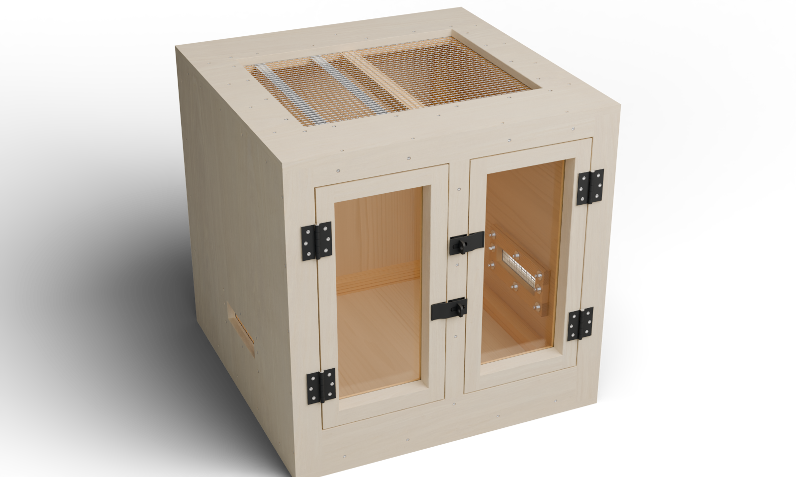
Full exterior veneer: the roof, faces, edges and reveals are included in this guide’s coordinated veneer schedule and geometry. Supplier balance, bond and actual-stack acceptance remain required. Natural grain and color vary.
About these previews
Rendered from this enclosure’s actual reference geometry. Veneer layers preserve service seams and bare hardware seats. The 3D viewer shows maple; these choices change the main picture. Texture scans by Jenelle van Heerden via Poly Haven, CC0 illustrate appearance and are not delivered veneer samples.
Two independently latched acrylic doors, a removable screened roof, inside screen captures and a supported central roof rib. Follow 49 pictured operations with checks before continuing.
Construction holds: received material and hardware acceptance, custom hinge-pad mounting, veneer balance/bond, glazing fit, prototype construction, physical testing and qualified review remain open.
Receive and trial the exact products before dependent final cuts. This is P04-03’s own 30-inch (762 mm) cube with removable-pin hinges and a rear spacer-and-cap glazing system. Recalculate every affected part if stock or hardware changes.
Measurement
Reference
Bare case
30 × 30 × 30 in (762 × 762 × 762 mm)
Reference covered wood
30.061 in (763.55 mm) × 30.061 in (763.55 mm) × 30.061 in (763.55 mm)
Maximum covered wood
30.092 in (764.34 mm) × 30.092 in (764.34 mm) × 30.092 in (764.34 mm)
Each bare door
11.32825 in (287.74 mm) × 22.469 in (570.71 mm)
Bare door gaps
Hinge/top/bottom 3/16 in (4.76 mm); latch 5/32 in (3.97 mm)
Minimum final operating gap
1/16 in (1.59 mm); containment acceptance is separate
Each acrylic pane
Width 9.172 in (232.97 mm); height 20.344 in (516.74 mm); thickness 0.22 in (5.59 mm)
Hinge pin service allowance
4 in (101.6 mm) above upper pin and 14 in (355.6 mm) in front; enlarge for actual tools and helper
Full cured veneer layer
Reference 0.0305 in (0.77 mm); maximum 0.046 in (1.17 mm)
Measurements: in means inches; mm means millimetres. Exact decimals are retained for fitting. Hardware projects beyond the wood. Assembly coordinates start at outside LEFT (X), outside FRONT (Y) and FLOOR UNDERSIDE (Z), unless a local part edge is named.
Tools, terms and workholding
Prepare a padded supporting bench, helpers, clamps, straight cauls, tape, square, caliper and marking knife. Use supported saw and guided router/jigsaw setups, a chisel, block plane, sliding bevel and stopped drills. Make narrow pieces from safely supported long stock; use the tool’s guarded carrier or a machining service.
Use root-matched pilots, clearance bits, the actual 82-degree head seat and correctly fitting Phillips drivers. Two suitable thin wrenches must fit the received locknut and closed cover; the modeled 3/8 in (9.53 mm) hex envelope is only a reference. Metal needs a vise, supported cutting/drilling tools and files. Veneer needs a sharp knife, straightedge, cutting board and supplier-approved scraper.
Wear eye/hearing protection, control dust and ventilate coatings. Protect hands from sharp mesh and metal. Keep gloves, fingers and loose clothing away from rotating tools. Clamp small work and support the waste.
Term
Meaning
Cleat / ledger / post
Screw-receiving strip / horizontal support / vertical bearing support
Stile / rail
Vertical / horizontal frame member
Caul / lamination
Straight board spreading clamp pressure / layers glued together
Half-lap / recess
Two half-thickness overlapping ends / shallow pocket
Pressure-sensitive adhesive / relative humidity / bill of materials / ethylene propylene diene monomer rubber
Use the actual-stock worksheet
Record plywood thickness: t = ______ in / ______ mm. These equations preserve the bare 30-inch (762 mm) case and assume the accepted front-frame and solid-support sections. Changed sections require a coordinated revision.
Part or opening
Equation, inches
Reference
P01 floor and P02 roof
30 × 30
30 × 30 in (762 × 762 mm)
Side height; back height and width
30 − 2t
28.594 in (726.29 mm)
Each front opening width
(30 − 2t − 3 × 1.75) ÷ 2
11.672 in (296.47 mm)
Front opening height
30 − 2t − 4 − 1.75
22.844 in (580.24 mm)
Bare leaf width
Measured opening − 3/16 − 5/32
11.32825 in (287.74 mm)
Bare leaf height
Measured opening − 3/16 − 3/16
22.469 in (570.71 mm)
C03–C06 side cleats
30 − t − 3
26.297 in (667.94 mm)
C07/C08/C10 cross ledgers
30 − 2t − 3
25.594 in (650.09 mm)
C11 central roof rib
30 − t − 1.5
27.797 in (706.04 mm)
C12 centre bearing post
Actual gap; reference 30 − 2t − 3
25.594 in (650.09 mm)
C13/C14 rear bearing posts
Actual gap; reference 30 − 2t − 4.5
24.094 in (611.99 mm)
Use matching received offcuts as gauges and transfer actual gaps to story sticks. Dependent frame cuts, pane/spacer clearances, hardware positions and veneer blanks must change together. Rounded tape equivalents are for orientation, not final machining settings.
Tools / setup: Tape, square, caliper, pencil and the tools named in this operation
Before you begin: No load rating, stacking permission or species approval is supplied.
Plan support, handling and removal space
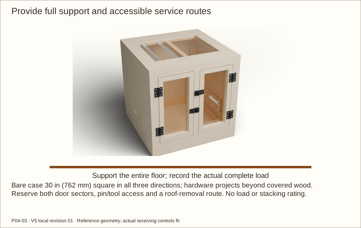
Start from the bare 30 in (762 mm) × 30 in (762 mm) × 30 in (762 mm) case. At the maximum allowed covering, the wood envelope is 30.092 in (764.34 mm) in each direction; hinges and hasps project farther.
Provide a rigid, level support under the entire finished floor. Record the actual shell, substrate, contents and equipment weights; have that complete load and stability assessed.
Reserve both door swing sectors, at least 14 in (355.6 mm) in front and 4 in (101.6 mm) above the upper hinge pin, plus the actual hand, tool and helper space. Rehearse a route to lift off the roof and remove each supported door.
Check before continuing: Support, helpers and all maintenance paths are recorded.
Parts: Accepted material samples and the named workshop setup
Tools / setup: Tape, square, caliper, pencil and the tools named in this operation
Before you begin: Unresolved inputs remain holds; an illustration is not product approval.
Resolve the receiving holds
Read H01–H06 before buying or cutting dependent parts. Keep the actual measurements and supplier decisions on the worksheet.
Choose one maple, white-oak or walnut system. Confirm backing, adhesive, sealer, finish and balancing method. PSA in a product name means pressure-sensitive adhesive.
Use the listed material and hardware identities. A substitution requires revising the affected dimensions, holes, instructions, purchases and pictures together.
Check before continuing: Every input required by the next operation is accepted.
Parts: P01 · Continuous floor; P03 · Left side with lower inlet; F01 · Front outer stile; G1 · Door 1 OPTIX pane
Tools / setup: Tape, square, caliper, pencil and the tools named in this operation
Measure, mark and acclimate the stock
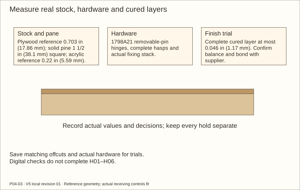
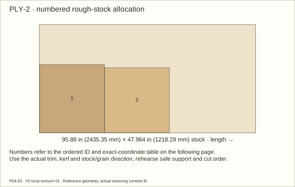
Measure plywood at its corners and centre. Reference thickness is 0.703 in (17.86 mm); sheet layouts use 95.88 in (2435.35 mm) × 47.964 in (1218.29 mm) usable stock. The listing has conflicting thickness fields, so actual received sheets govern.
Check straight, sound 1 1/2 in (38.1 mm) square pine, 3/4 in (19.05 mm) × 7 1/4 in (184.15 mm) boards, 1/4 in (6.35 mm) lattice, 3/8 in (9.53 mm) square poplar, acrylic, mesh, steel and pads. Reject damaged or voided screw-bearing areas.
Acclimate as the material and veneer suppliers require. Label FRONT, INSIDE, LEFT or RIGHT, part ID and a measuring corner; save matching offcuts.
Check before continuing: Stock gauges and datums are recorded without rounding away a fit change.
Required wait: Use confirmed supplier acclimation requirements; no invented duration applies.
Parts: Accepted material samples and the named workshop setup
Tools / setup: Tape, square, caliper, pencil and the tools named in this operation
Before you begin: Never feed a short loose strip through a planer or trap the waste beside the blade.
Prepare supported tool setups
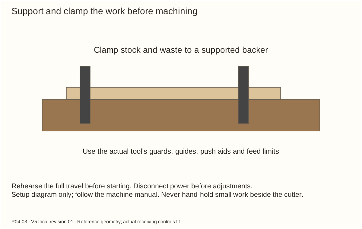
Set up a flat padded bench, clamps and supported infeed/outfeed. Rehearse the largest panel and the empty case turn with help.
Use guards, riving knife, push aids and minimum workpiece lengths required by the actual tools. Make narrow strips from long supported stock with a suitable carrier or milling service.
Clamp drill and router work to a backer. Disconnect tools before changing cutters, guides or stops.
Check before continuing: Every cut has stable support and a safe hand path.
Parts: Accepted material samples and the named workshop setup
Tools / setup: Stopped drill, countersink, caliper, actual screws, clamps and backer
Before you begin: Do not enlarge the metal hinge or hasp countersinks to force a screw to fit.
Trial clearance holes, pilots and head seats
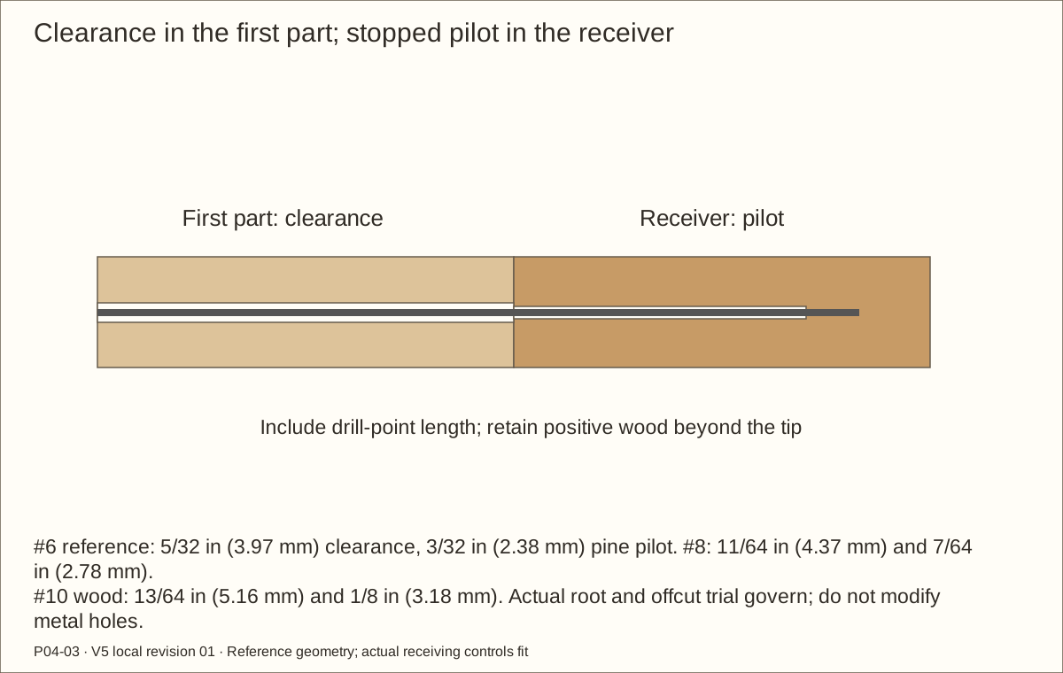
A clearance hole lets the first part slide along the screw; a smaller pilot guides the thread in the receiver. Trial matching offcuts with the actual screw.
Reference clearances are 5/32 in (3.97 mm) for #6, 11/64 in (4.37 mm) for #8 and 13/64 in (5.16 mm) for #10 wood screws. Reference pine pilots are 3/32 in (2.38 mm), 7/64 in (2.78 mm) and 1/8 in (3.18 mm) respectively; actual root diameter and the trial govern.
Screen bolts use 1/4 in (6.35 mm) through holes and 82-degree flat-head seats. Trial the head in sound wood. Include the drill point in a stopped depth; leave at least 1/16 in (1.59 mm) wood behind each tip.
Check before continuing: Heads seat without splitting, crushing or exposed screw points.
Tools / setup: Tape, square, caliper, pencil and the tools named in this operation
Before you begin: Supplier or qualified acceptance and a full-size trial are still required; no hinge capacity is inferred.
Trial the removable-pin hinges and hasps
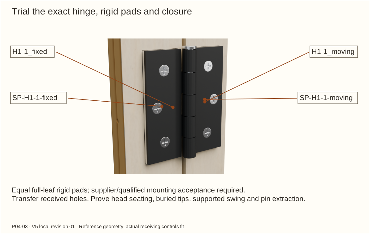
Use matching fixed and moving frame offcuts. Trial a 3 in (76.2 mm) × 1 1/16 in (26.99 mm) × 1/8 in (3.18 mm) rigid aluminium pad under each hinge leaf, with at least 7/64 in (2.78 mm) actual pad thickness. Custom mounting acceptance remains H02.
Fit the exact McMaster 1798A21 hinge with its barrel forward and pin removable upward. Transfer the received holes and trial the listed #8 × 1 1/4 in (31.75 mm) flat-head screws. Both pads must bear fully on bare wood.
Trial the N305-979 narrow base on the trimmed latch stile and its square swivel plate on the 1 3/4 in (44.45 mm) centre post. Keep all seven holes and each plate fully supported; transfer received hardware, not the picture.
Check before continuing: Hardware seating, sound edge margins, supported swing and actual pin removal are accepted.
Parts: D1A · Door 1 half-lapped stile; D1B · Door 1 half-lapped stile; D1C · Door 1 half-lapped rail; D1D · Door 1 half-lapped rail
Tools / setup: Tape, square, caliper, pencil and the tools named in this operation
Make a full-size veneer and balance trial
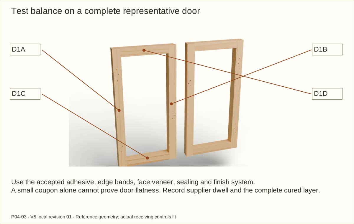
Use reserved stock to make a representative complete door frame. Apply the proposed face, edge, adhesive, sealing and finish system; a small coupon alone cannot show door balance.
Follow the supplier’s accepted balancing, pressure and dwell instructions. Measure the complete cured layer, including adhesive and coatings: no specified face may exceed 0.046 in (1.17 mm).
Record flatness, bond, finished gaps and hardware operation under the intended conditions. An added backing layer or changed stock gauge requires a coordinated revision.
Check before continuing: The cured complete-door trial stays flat and fits the accepted hardware.
Required wait: Use confirmed adhesive dwell and full coating cure; these are separate waits.
Parts: D1A · Door 1 half-lapped stile; Q1L · Door 1 separate spacer L; B1L · Door 1 separate flat cap L; G1 · Door 1 OPTIX pane; E1L · Door 1 plain EPDM rear cushion L
Tools / setup: Tape, square, caliper, pencil and the tools named in this operation
Before you begin: Do not stack foam, glue the pane or tighten screws to force an incorrect stack.
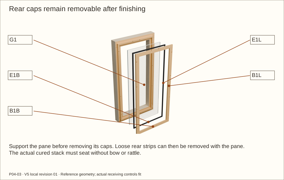
Trial the rear spacer-and-cap glazing
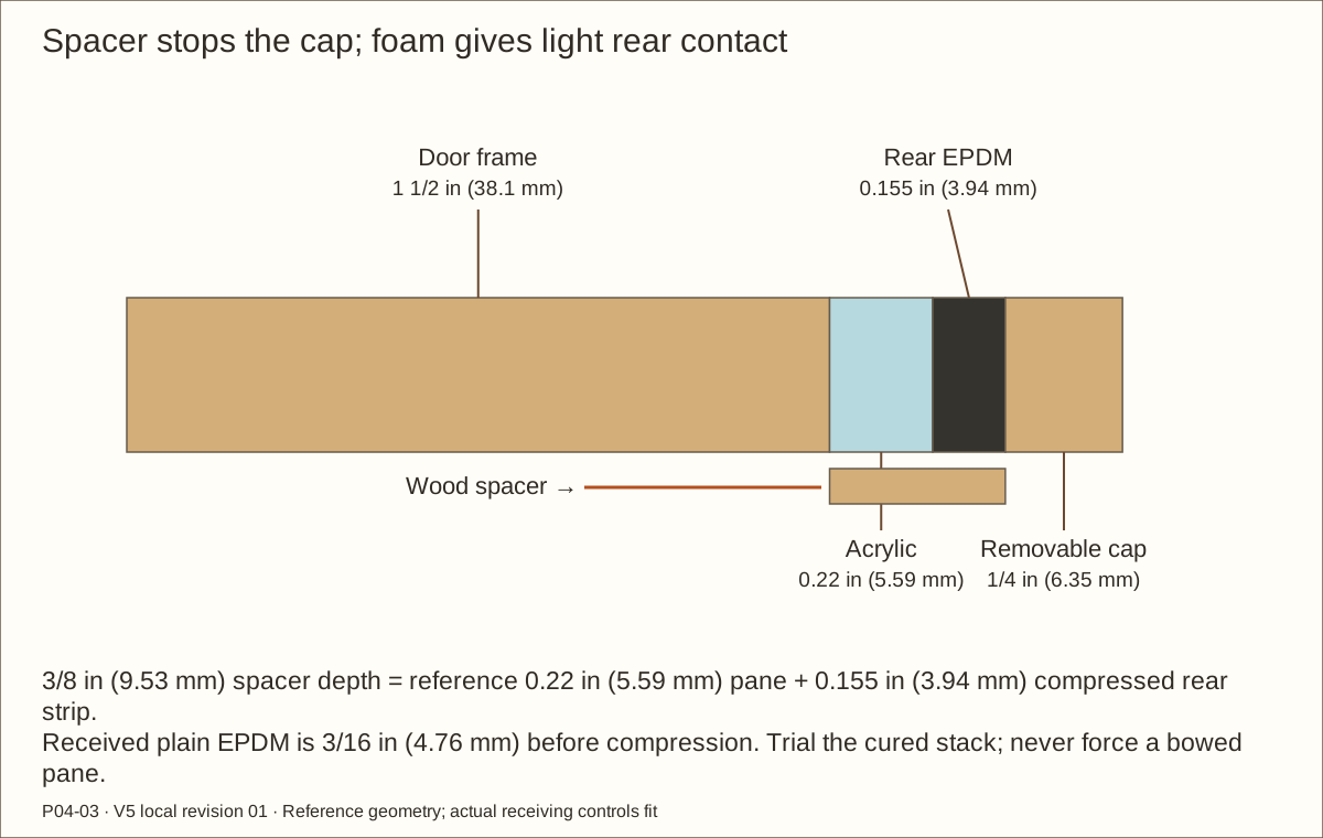
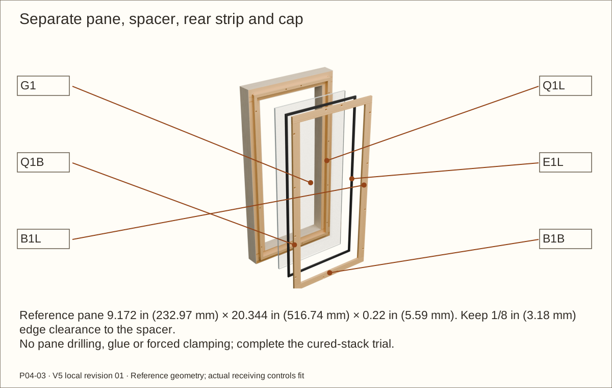
Make a same-stock sample with the actual 3/8 in (9.53 mm) rear spacer and 1/4 in (6.35 mm) cap. The cap stops on the wood spacer; there is no routed glazing pocket in this build.
Finish and fully cure the sample. Fit the actual 0.22 in (5.59 mm) reference acrylic and plain 3/16 in (4.76 mm) EPDM rear strip. The modeled 0.155 in (3.94 mm) compressed strip is a fit reference, not an approved force.
Maintain 1/8 in (3.18 mm) pane edge clearance to the surrounding spacers. The cap must seat with light strip contact and no pane bow. Resolve actual stack, finish compatibility and contact with the suppliers.
Check before continuing: The pane is supported and unbowed; caps seat on wood.
Required wait: Complete finish cure before measuring this trial.
9. Allocate the stock and rough-cut labeled blanks
Parts: P01 · Continuous floor; P02 · Roof with upper exhaust; P03 · Left side with lower inlet; P04 · Right side with lower inlet; P05 · Back
Tools / setup: Tape, square, caliper, pencil and the tools named in this operation
Allocate the stock and rough-cut labeled blanks
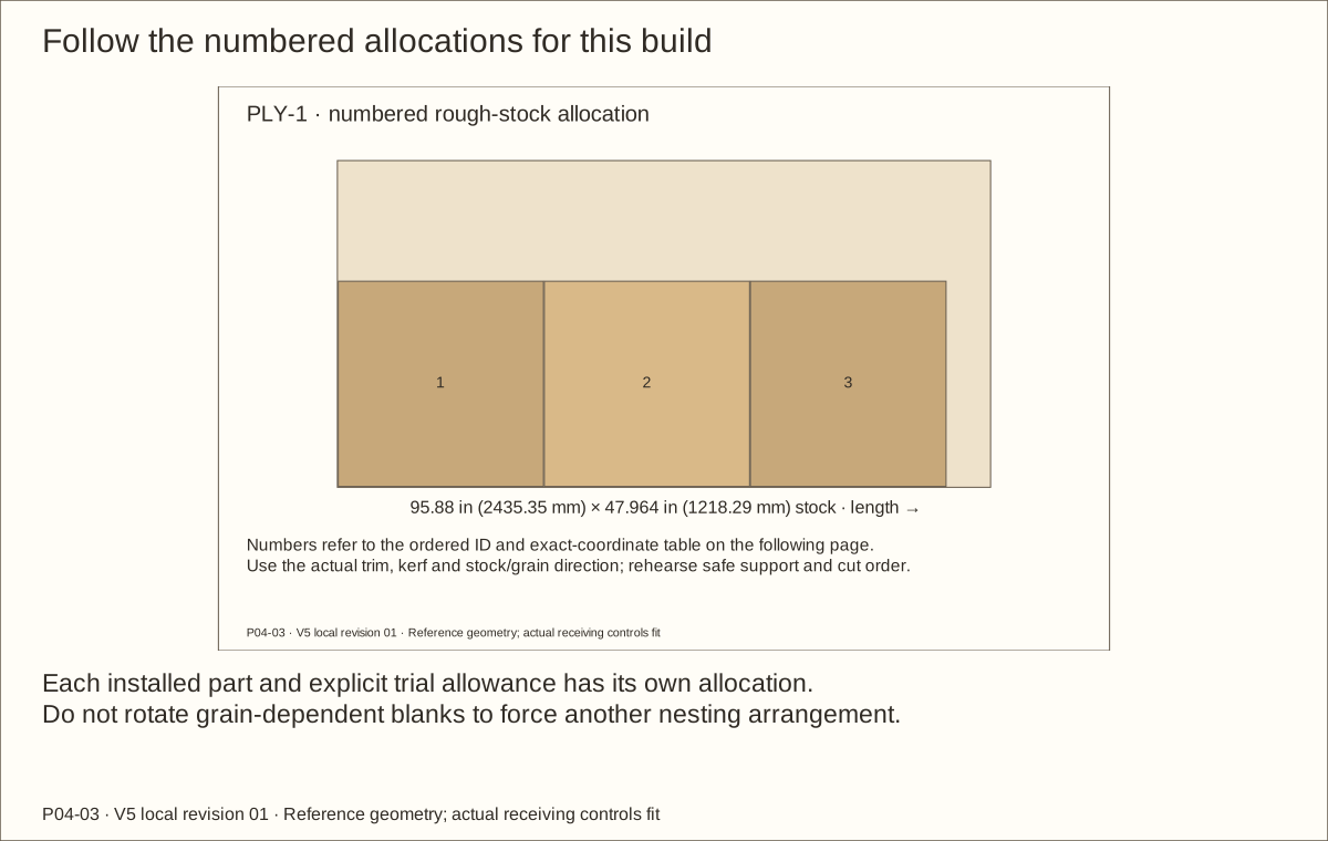
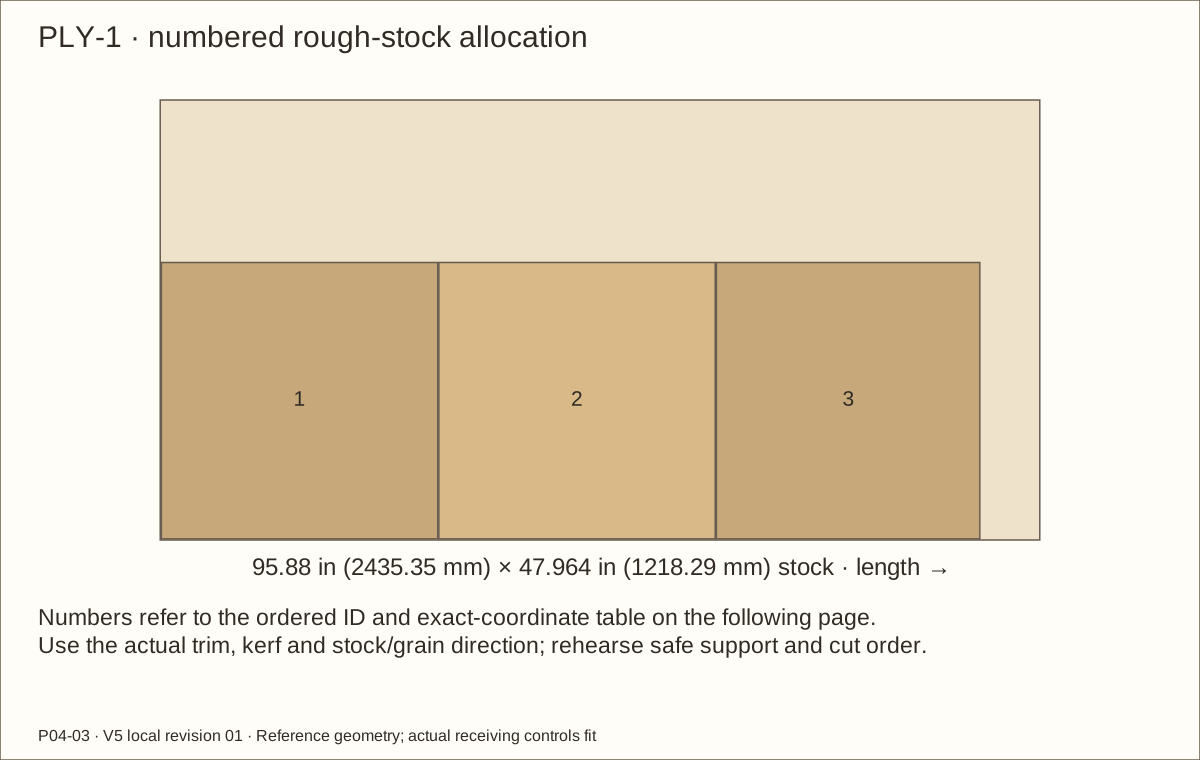
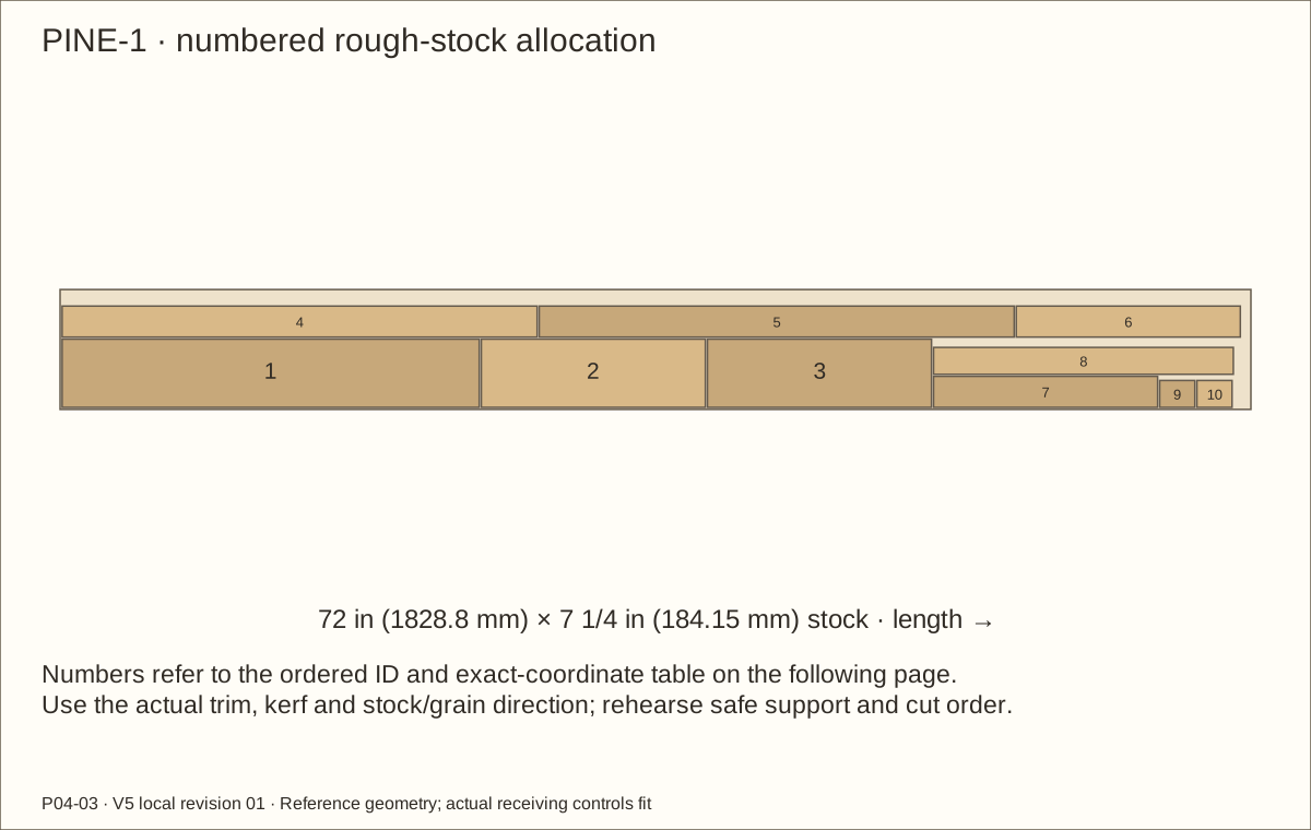
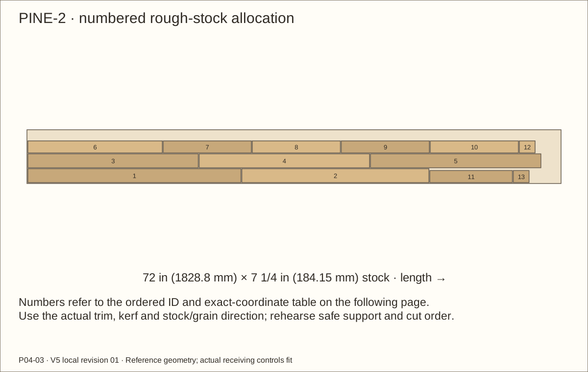
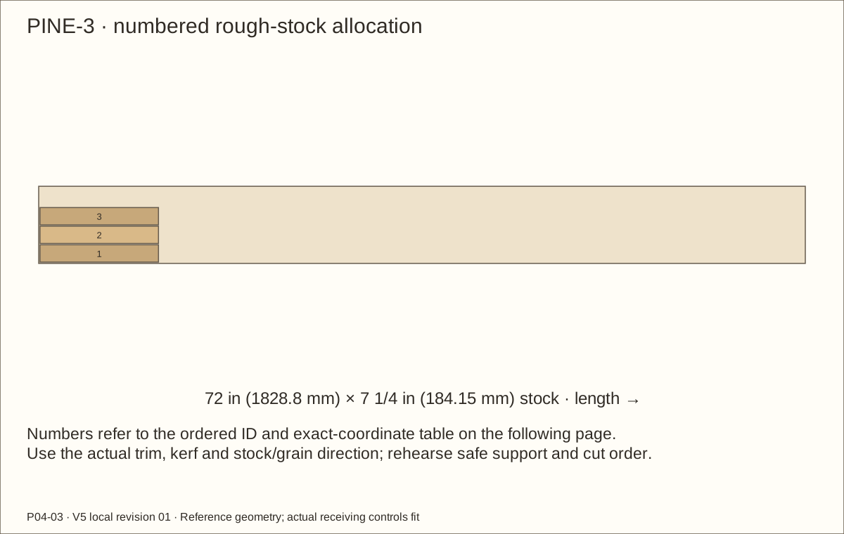
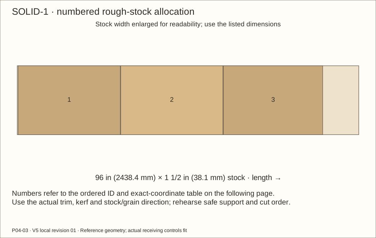
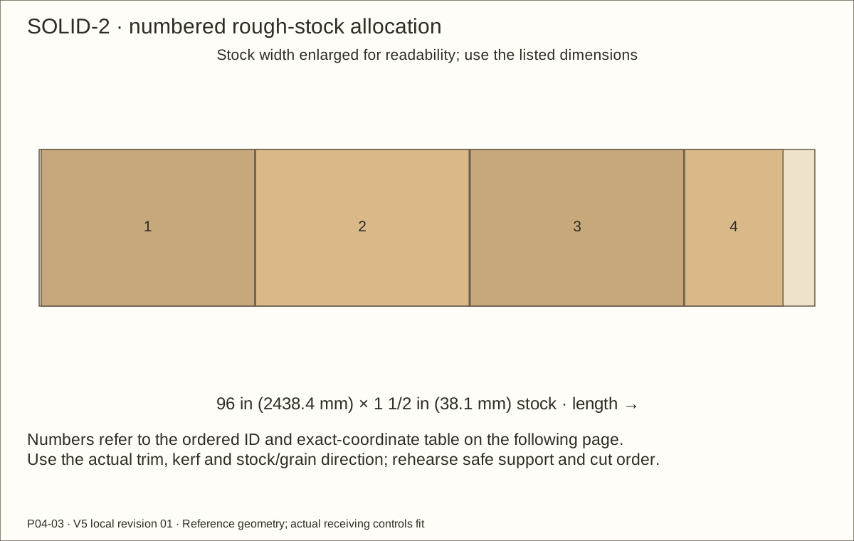
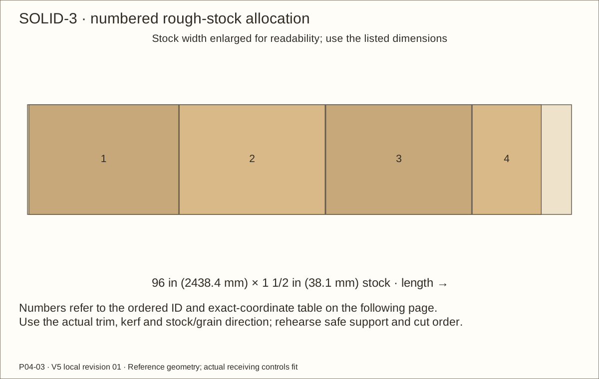
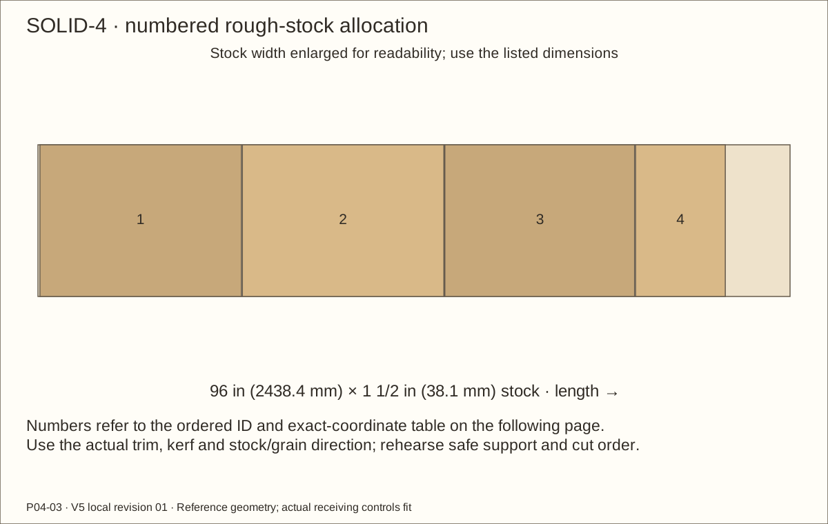
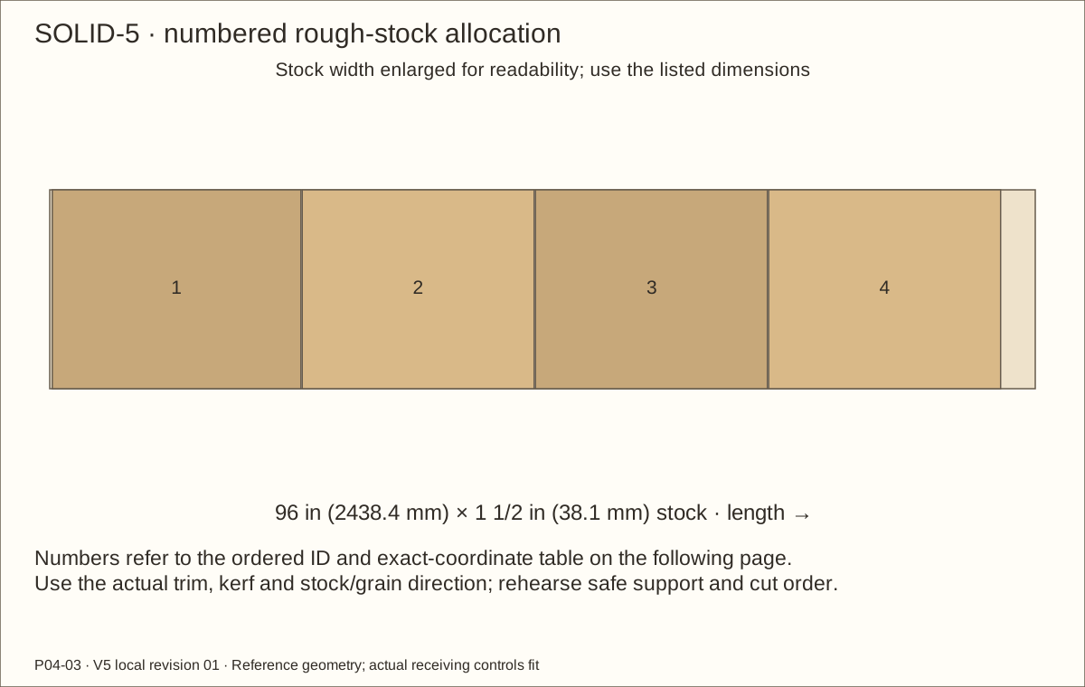
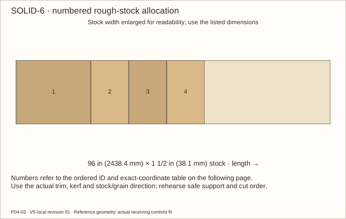
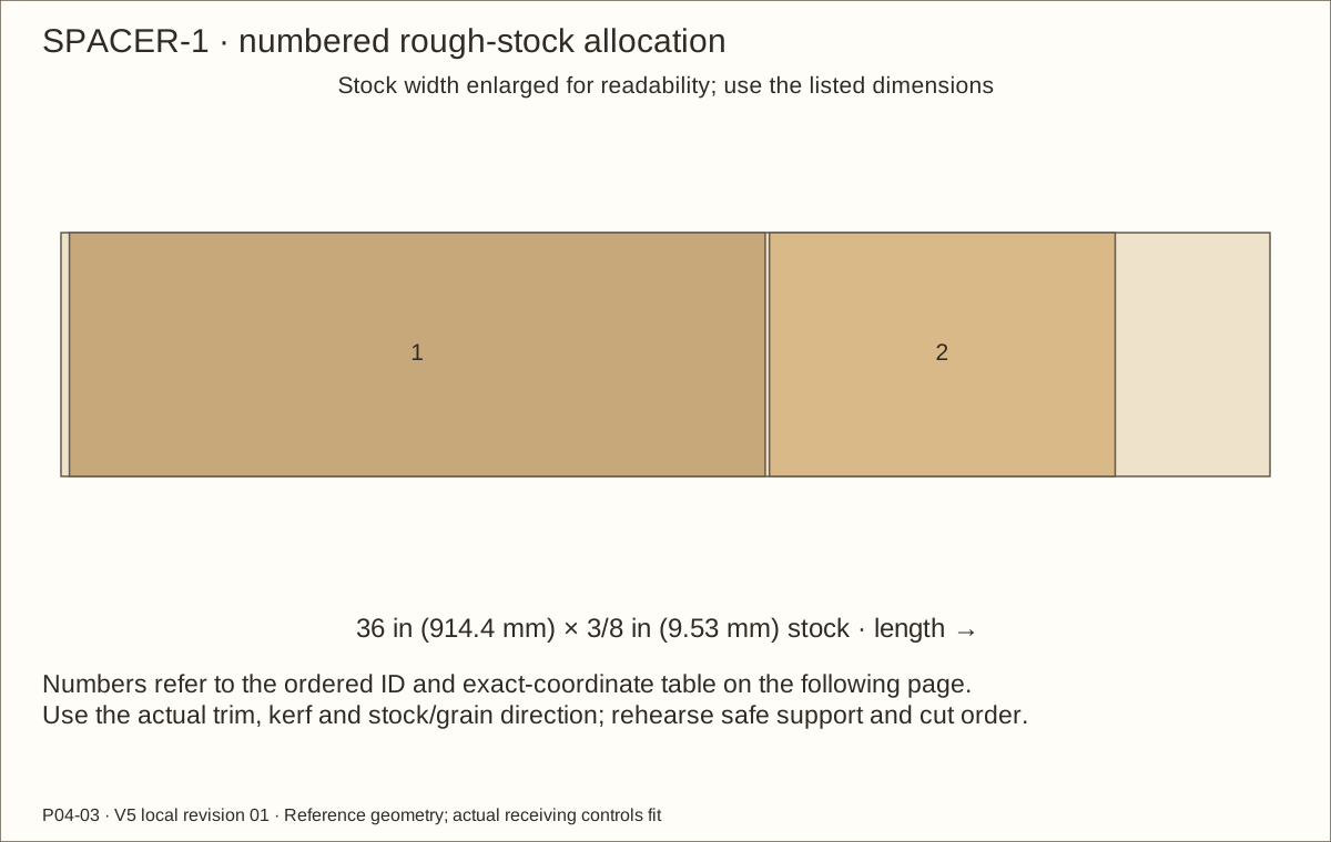
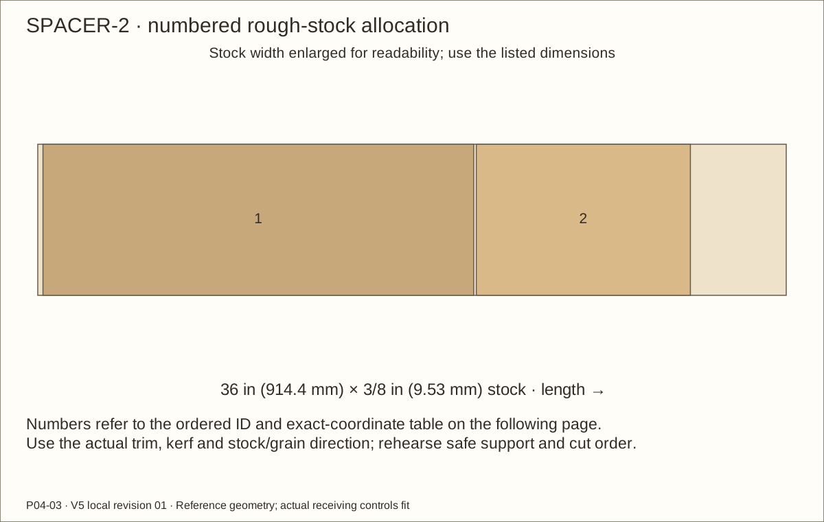
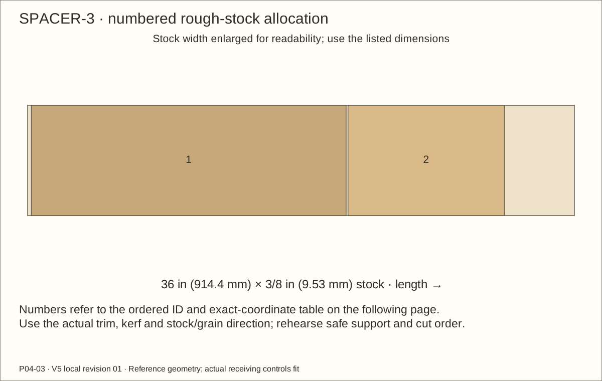
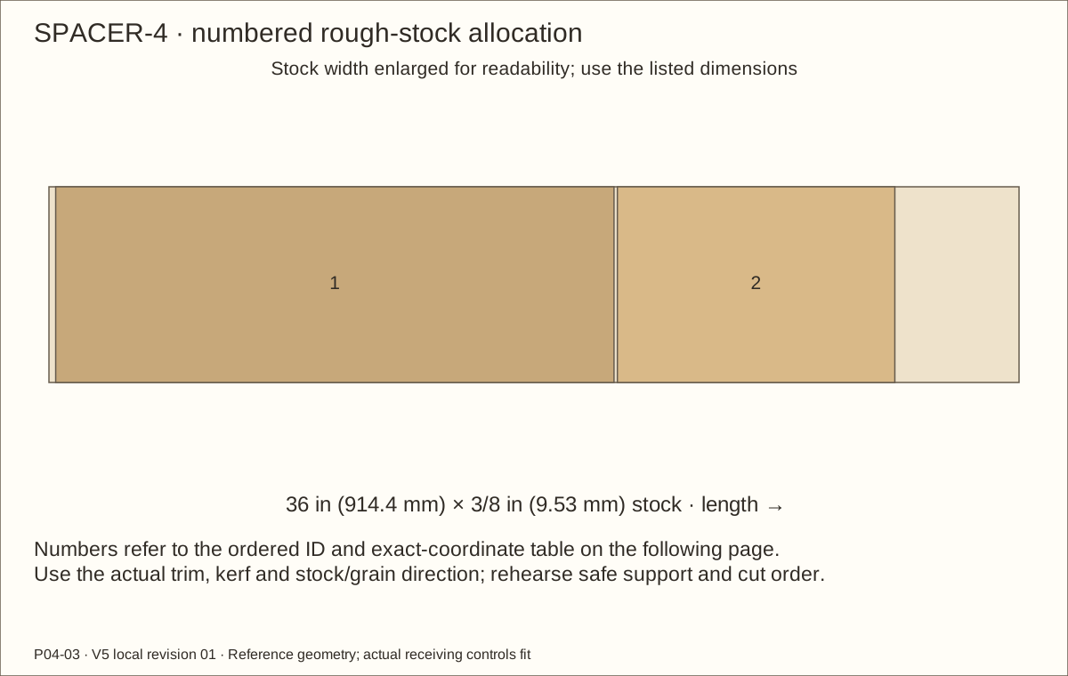
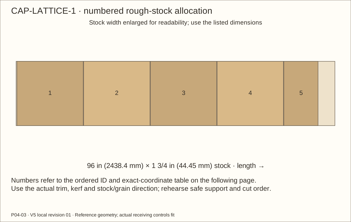
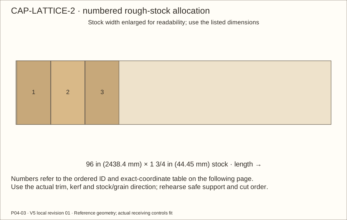
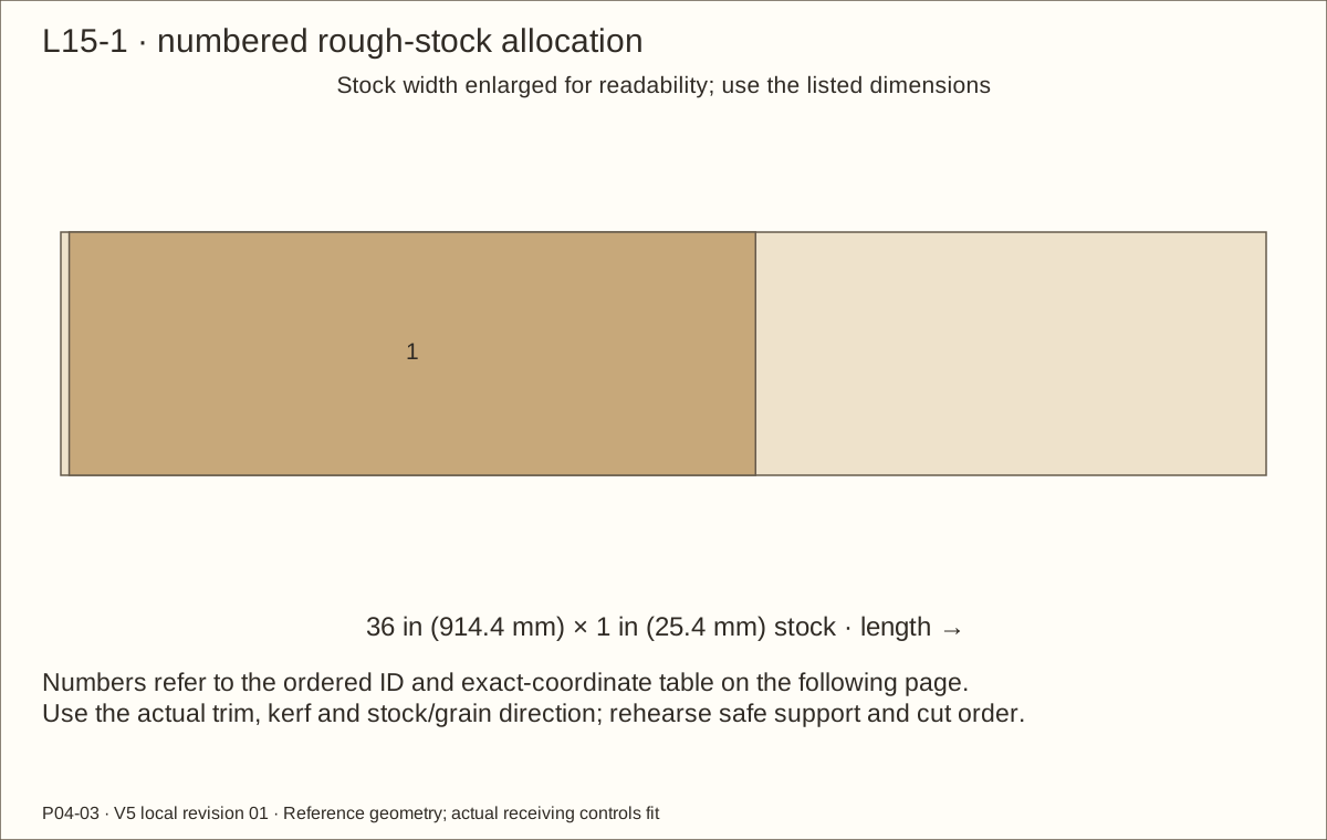
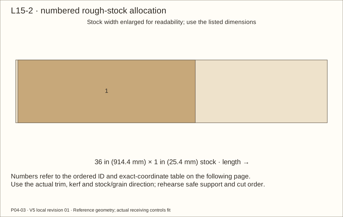
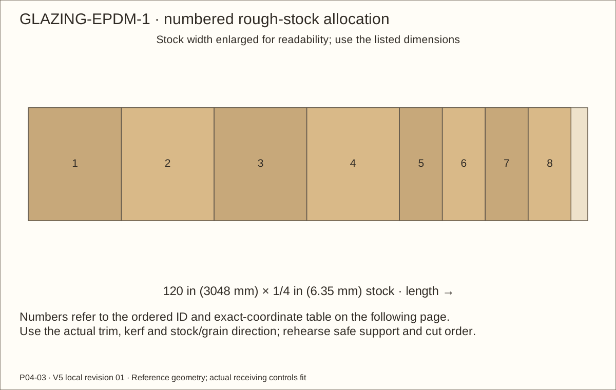
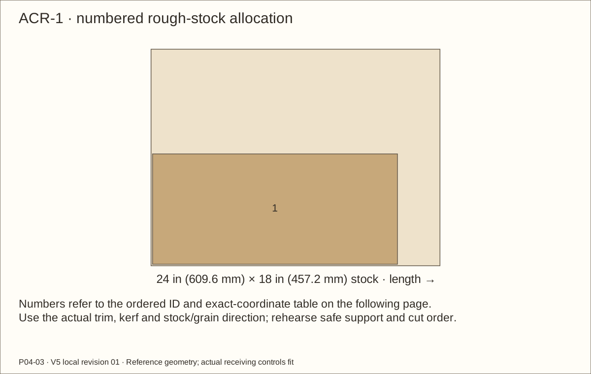
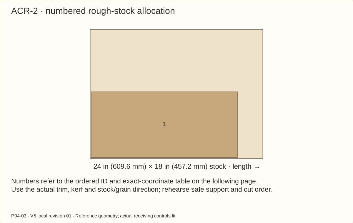
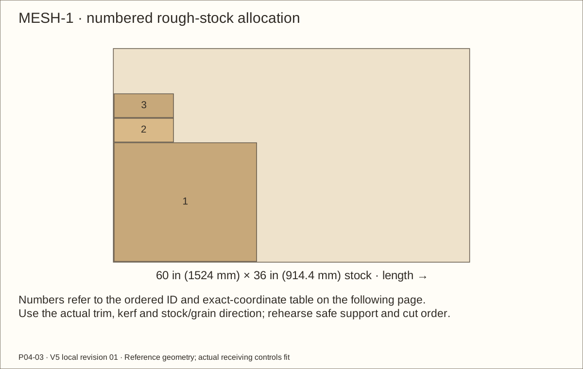
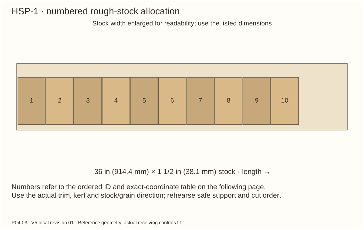
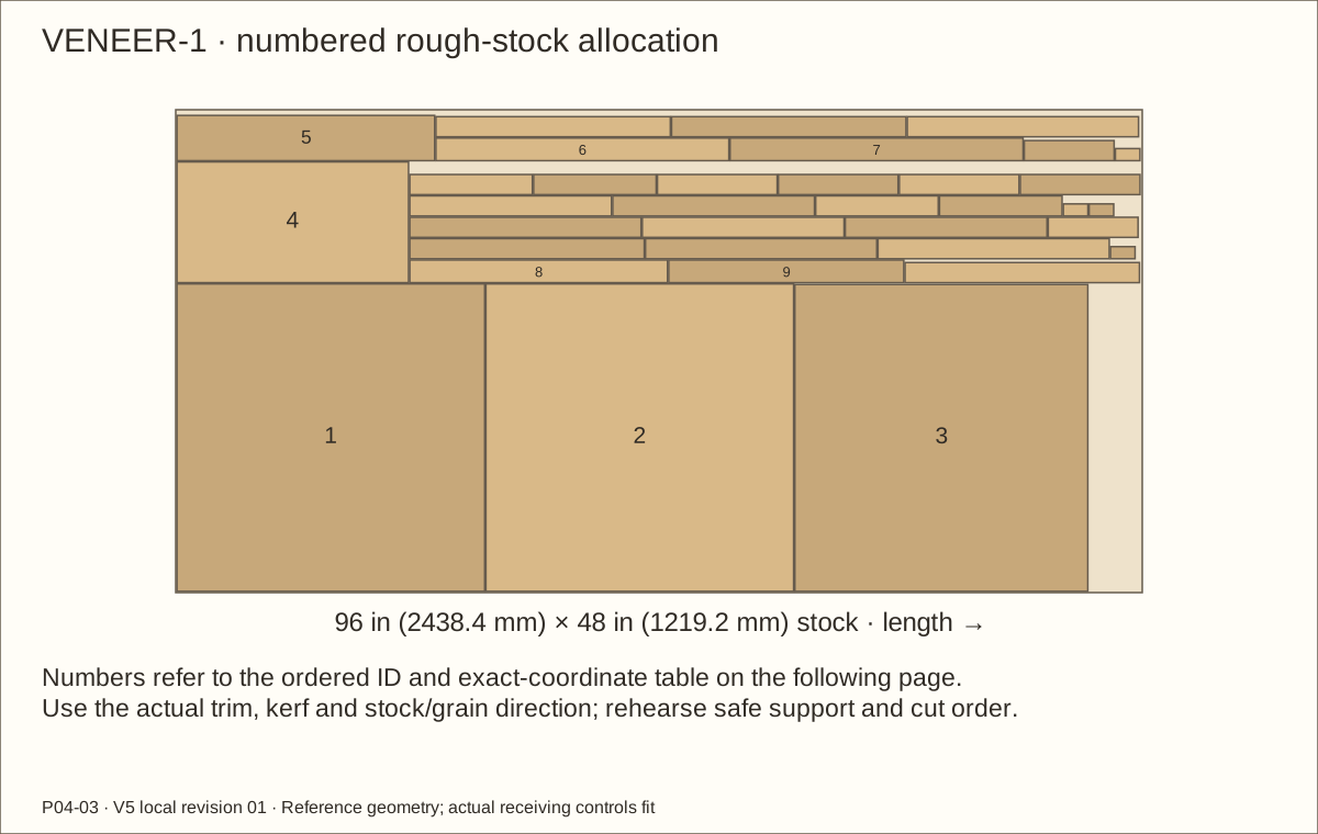
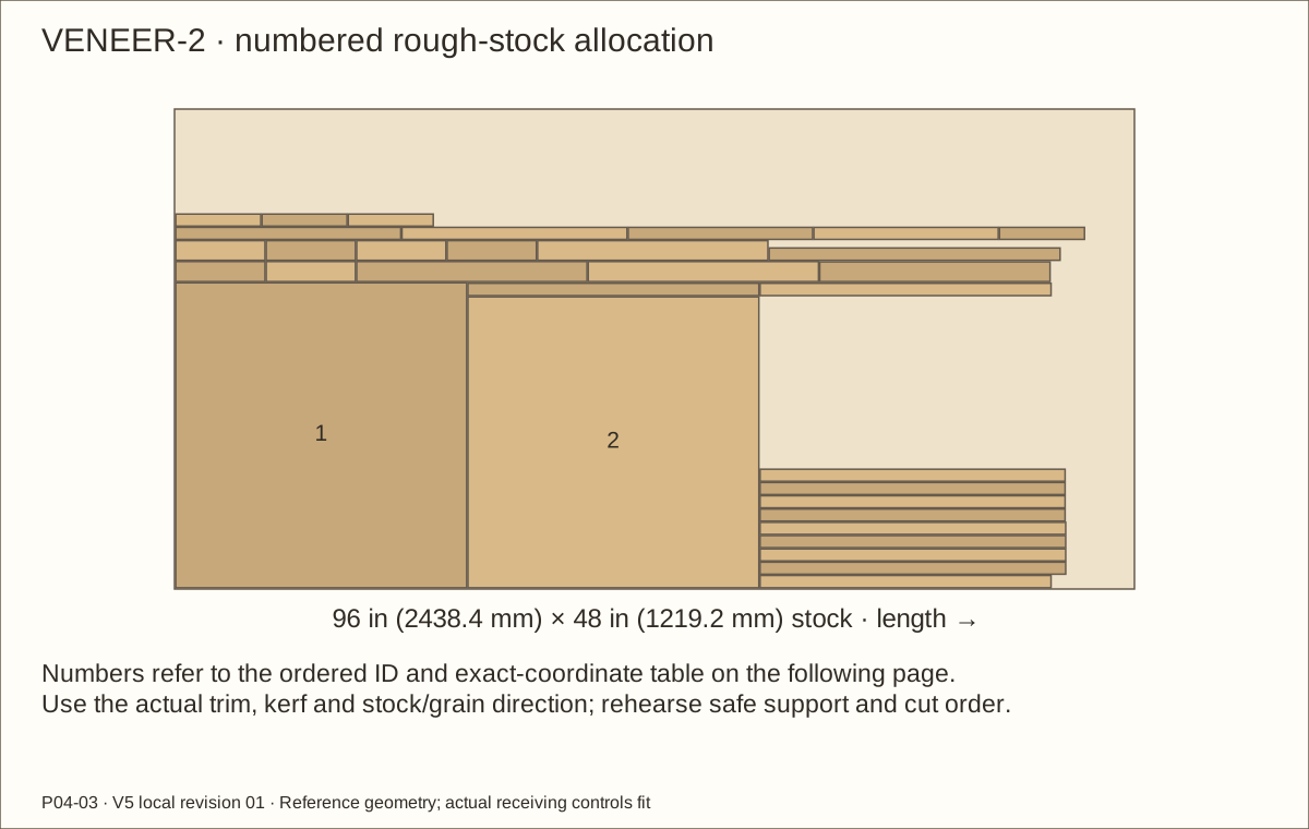
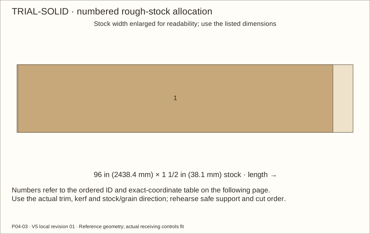
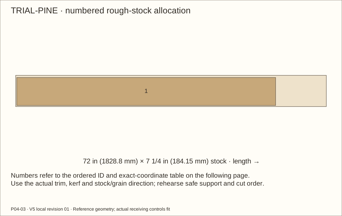
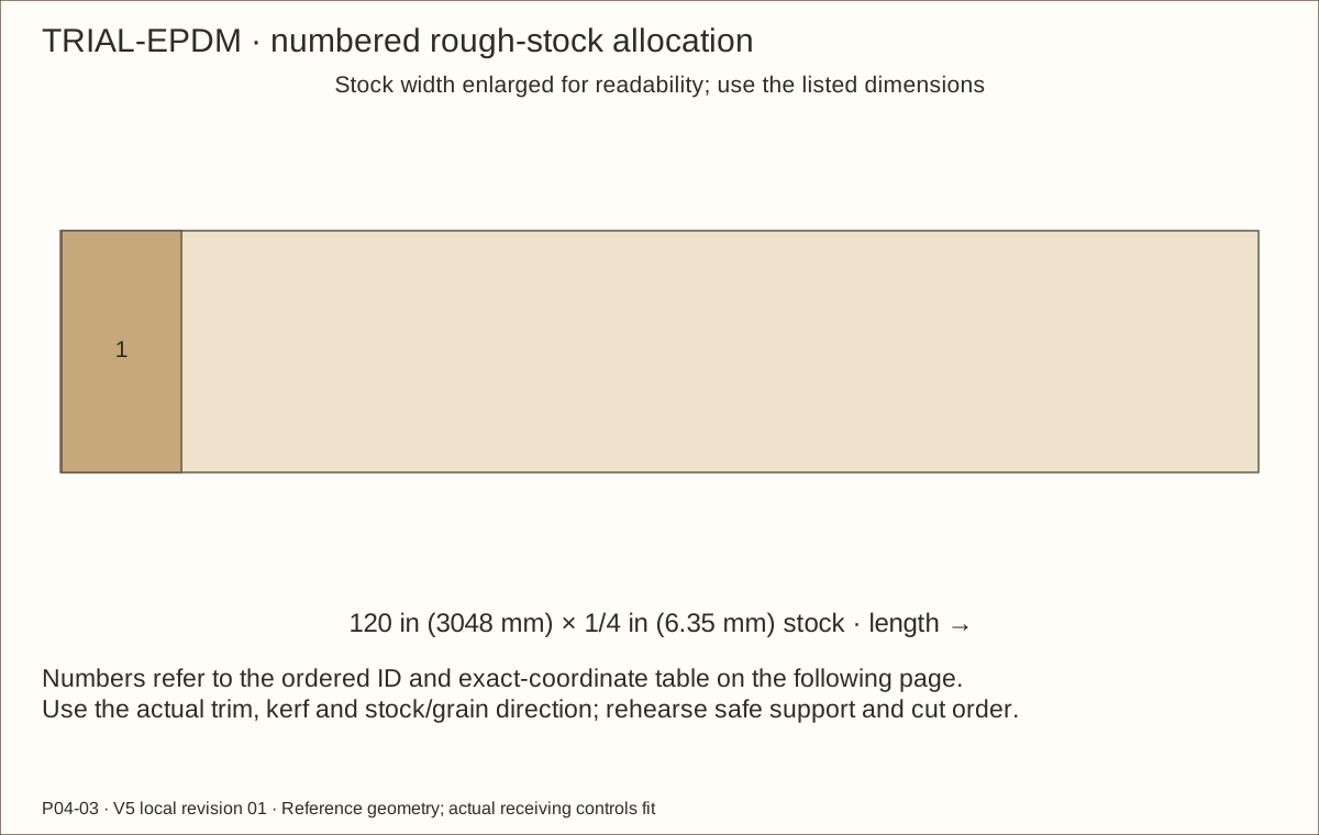
Follow this revision’s numbered stock layouts. Respect grain direction, end/edge trims and the reference 1/8 in (3.18 mm) saw kerf. Revise layouts if the measured blade or stock differs.
Keep installed parts separate from dedicated trial boards, veneer and foam. Retain rough fitting allowance and label every blank immediately.
Make supported long cuts before narrow strips. Use the exact finished dimensions and actual mating parts for final fitting; do not use a rounded tape reference as a machining setting.
Check before continuing: Every installed part and trial allowance is accounted for.
Parts: P01 · Continuous floor; P02 · Roof with upper exhaust; P03 · Left side with lower inlet; P04 · Right side with lower inlet; P05 · Back
Tools / setup: Tape, square, caliper, pencil and the tools named in this operation
Fit the five case panels
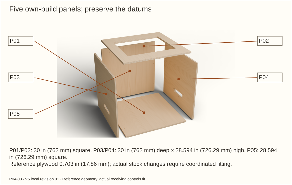
Finish floor P01 and roof P02 at 30 in (762 mm) square. Reference sides P03/P04 are 30 in (762 mm) deep × 28.594 in (726.29 mm) high between the 0.703 in (17.86 mm) panels.
Fit back P05 between the actual sides: reference 28.594 in (726.29 mm) square. Use a story stick, a strip marked directly from the received stack, to transfer both clear dimensions.
Check the height and width chains close to the intended bare 30 in (762 mm) envelope. Keep joint edges square; remove splinters without rounding the measuring faces.
Check before continuing: Paired sides match and the dry case dimensions close correctly.
Tools / setup: Supported jigsaw/router, guide, clamps, square and backer
Before you begin: Unsupported waste can fall, tear the face or pinch the blade.
Cut the roof aperture
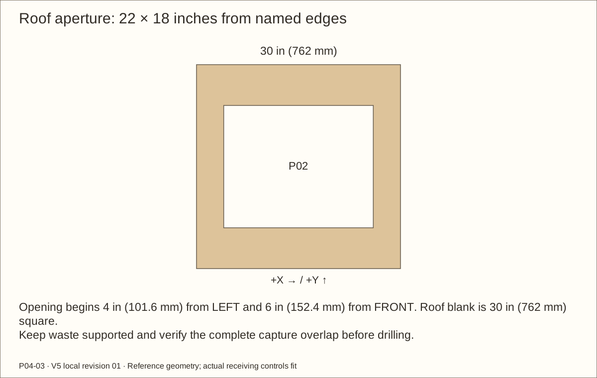
On a supported roof blank, mark the 22 in (558.8 mm) × 18 in (457.2 mm) opening beginning 4 in (101.6 mm) from LEFT and 6 in (152.4 mm) from FRONT.
Clamp the waste and panel. Use the actual tool’s supported starter and guided-cut method; keep the border intact.
Compare the opening diagonals and dry-fit the 24 in (609.6 mm) × 20 in (508 mm) mesh allowance and six capture pieces. Do not enlarge the opening to compensate for a crooked cut.
Check before continuing: The opening is square and agrees with the named roof datums.
Parts: P03 · Left side with lower inlet; P04 · Right side with lower inlet
Tools / setup: Tape, square, caliper, pencil and the tools named in this operation
Cut the paired side ventilation openings
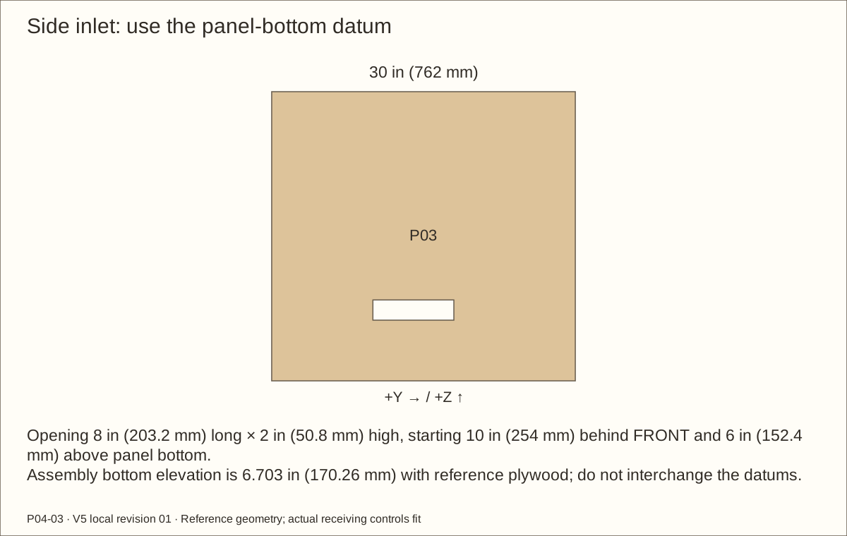
Mark each opening 8 in (203.2 mm) along the side × 2 in (50.8 mm) high, starting 10 in (254 mm) behind FRONT and 6 in (152.4 mm) above that side panel’s bottom edge.
When assembled on the reference floor, the opening bottom is 6.703 in (170.26 mm) above the floor underside. Keep panel-local and assembly datums distinct.
Cut on a backer with supported waste, then compare both sides. Dry-position the 10 in (254 mm) × 4 in (101.6 mm) screen and four inside battens around each opening.
Check before continuing: Both inlet openings and their capture overlap agree.
Tools / setup: Tape, square, caliper, pencil and the tools named in this operation
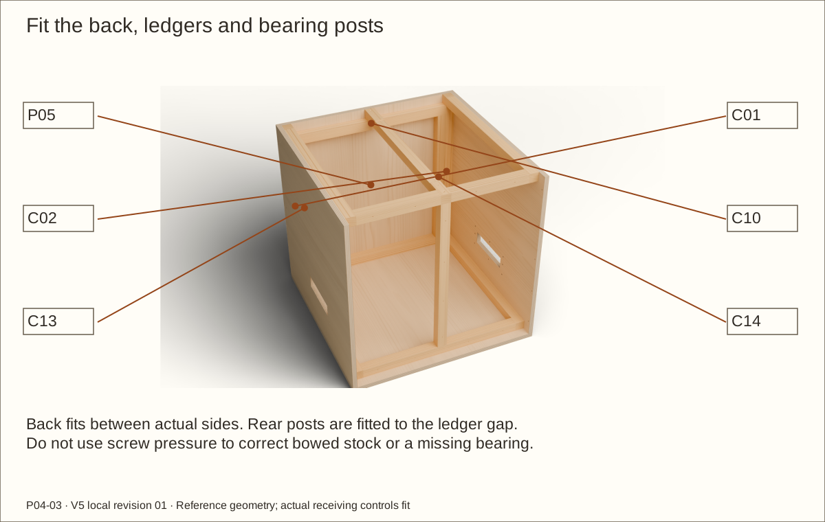
Cut the cleats, ledgers and bearing posts
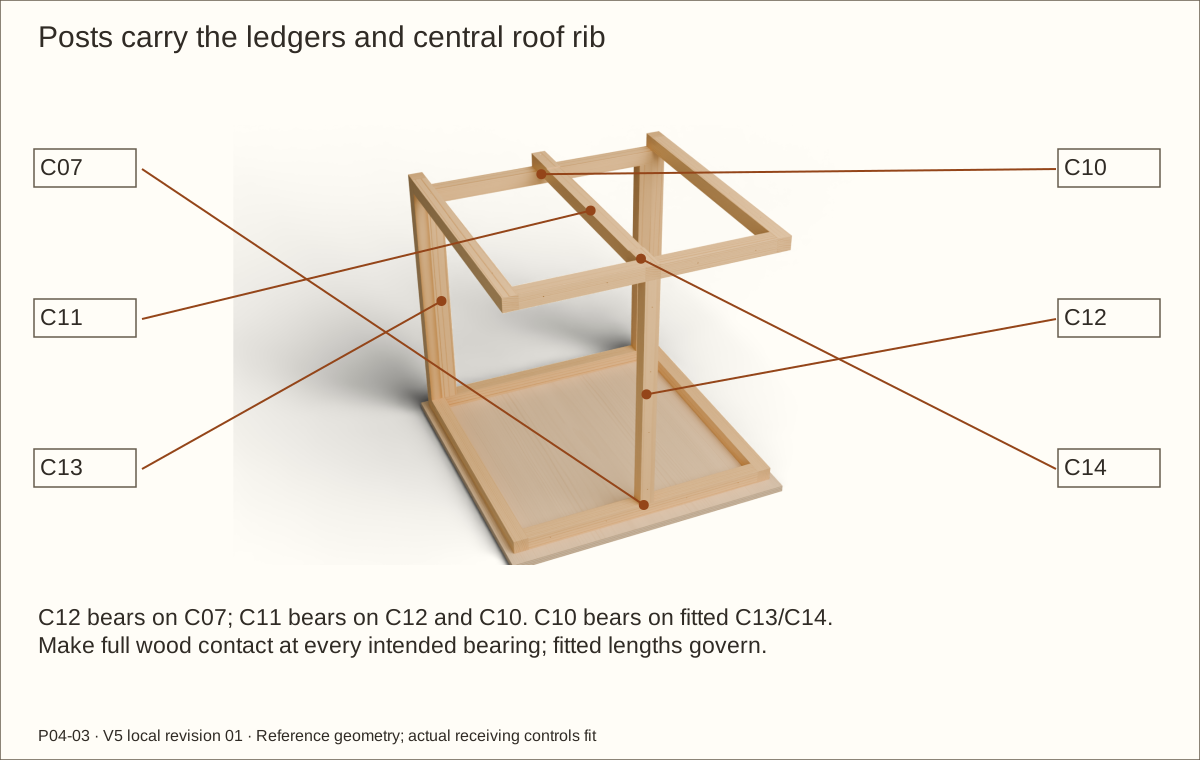
Use the labeled solid-pine cut schedule. A cleat is a strip behind a joint that receives screws; a ledger is a horizontal support; posts carry the ledgers and rib.
Fit C01/C02 rear corners and C03–C06 side cleats to the actual case. Fit C07/C08 lower front/rear ledgers between them. Keep the top-front C09A/C09B split for centre rib C11.
Rough C13/C14 rear bearing posts at 24 1/4 in (615.95 mm), then fit the actual gap; the reference final length is 24.094 in (611.99 mm). C12 supports C11 from C07. Never fill a short bearing post with an unexplained gap.
Check before continuing: All intended end bearings make full contact before fastening.
Parts: F01 · Front outer stile; F02 · Front outer stile; F03 · Front sill; F04 · Front header; F05 · Front centre stile; F06 · Rear centre stile
Tools / setup: Tape, square, caliper, pencil and the tools named in this operation
Cut and dry-stack the two front-frame layers
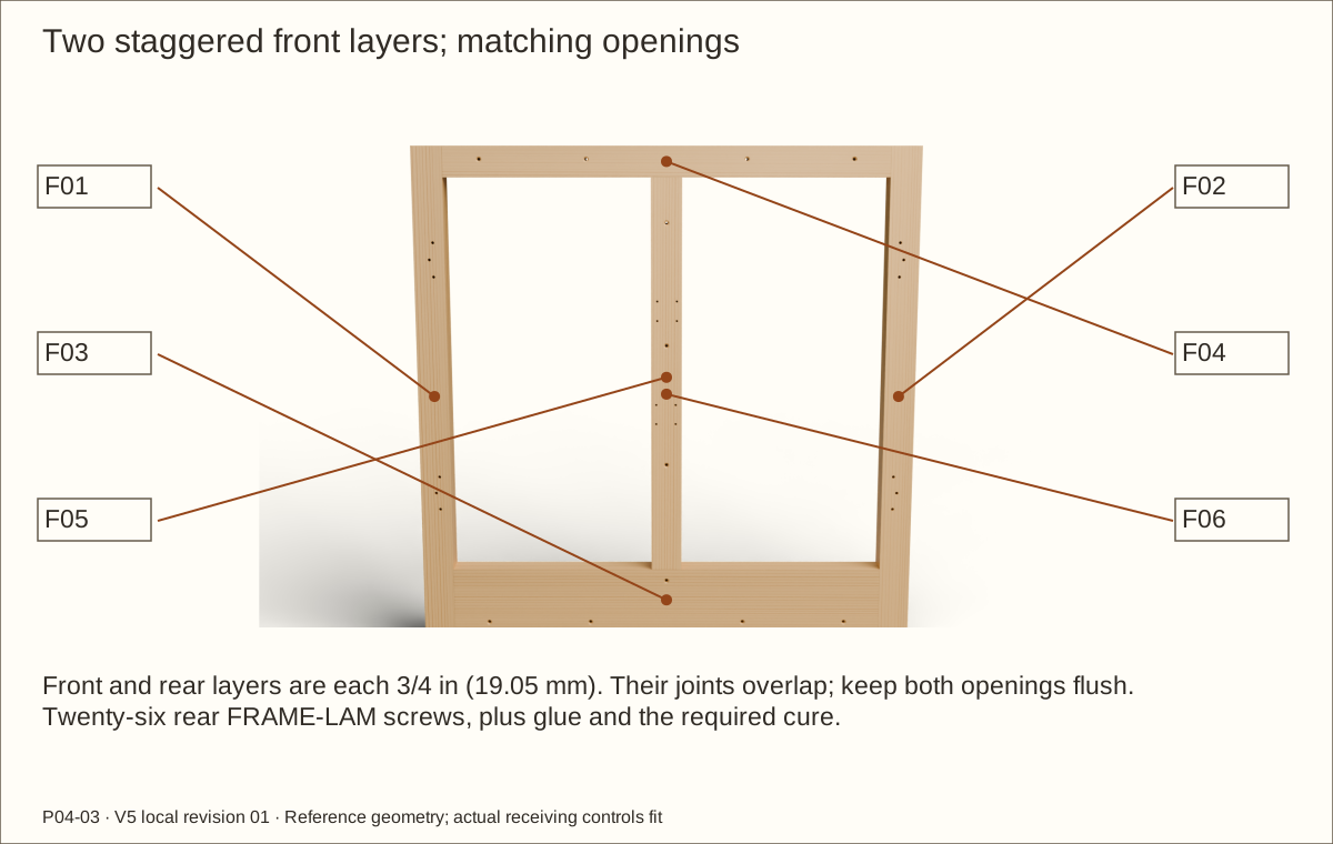
Cut F01–F12 from the reference 3/4 in (19.05 mm) board. Keep the front layer’s full-height outer stiles, sill, header and centre infill distinct from the staggered rear pieces.
Dry-stack both layers on a flat bench with their outside faces and door openings flush. F06 runs full height behind the centre; F07/F08 rear sills and F09/F10 rear headers end against it.
Check both openings, reference 11.672 in (296.47 mm) wide × 22.844 in (580.24 mm) high. Label every layer before separating it for glue.
Check before continuing: The staggered joints overlap correctly and the two openings are square.
Parts: F01 · Front outer stile; F02 · Front outer stile; F03 · Front sill; F04 · Front header; F05 · Front centre stile; F06 · Rear centre stile
Tools / setup: Tape, square, caliper, pencil and the tools named in this operation
Glue and screw the fixed front frame
Glue only clean bare mating wood with Titebond III. Above the conservative 47°F (8.3°C) application minimum, spread the maker’s specified amount and assemble within the actual working time.
Clamp the two layers flat and square; install the 26 FRAME-LAM #8 × 1 1/4 in (31.75 mm) screws from the rear. Use the station drawing, clear first layer and stopped pilot in the front layer.
Remove squeeze-out while appropriate for the glue instructions, keeping later glazing, veneer and hardware seats clean. Check diagonals before leaving the assembly clamped.
Check before continuing: The frame remains flat and square with all screw tips buried.
Required wait: Titebond recommends 30–60 minutes clamping for unstressed joints; stressed joints require 24 hours. Do not stress these new joints for at least 24 hours; colder conditions may require longer.
Parts: D1A · Door 1 half-lapped stile; D1B · Door 1 half-lapped stile; D1C · Door 1 half-lapped rail; D1D · Door 1 half-lapped rail
Tools / setup: Tape, square, caliper, pencil and the tools named in this operation
Before you begin: Make supported repeated cuts with the tool’s guarded fixture; do not hold a short end at a moving cutter.
Cut the door-frame half-laps
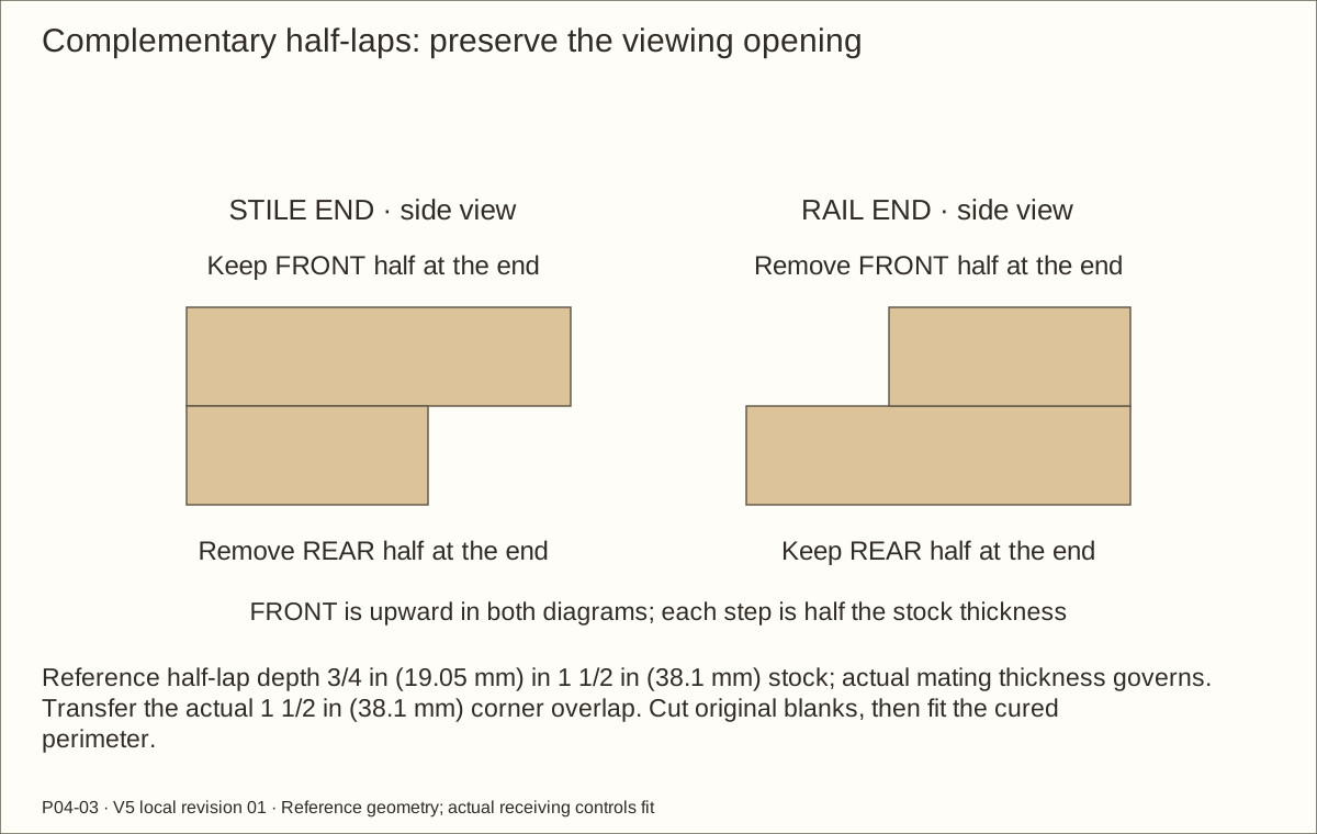
A half-lap removes half the thickness from two crossing pieces so they overlap flush. Start from the original door-frame blanks and transfer the actual 1 1/2 in (38.1 mm) corner width.
Remove the REAR half at both ends of each stile and the FRONT half at both ends of each rail. The reference depth is 3/4 in (19.05 mm); trial the actual stock so the combined joint stays 1 1/2 in (38.1 mm) thick.
Dry-fit both frames square with their original viewing openings retained. Label all four corners and do not reverse the shoulder faces.
Check before continuing: Each lap seats flat with no rocking or forced shoulder gap.
Parts: D1A · Door 1 half-lapped stile; D1B · Door 1 half-lapped stile; D1C · Door 1 half-lapped rail; D1D · Door 1 half-lapped rail; D2A · Door 2 half-lapped stile; D2B · Door 2 half-lapped stile
Tools / setup: Tape, square, caliper, pencil and the tools named in this operation
Glue and fasten both door frames
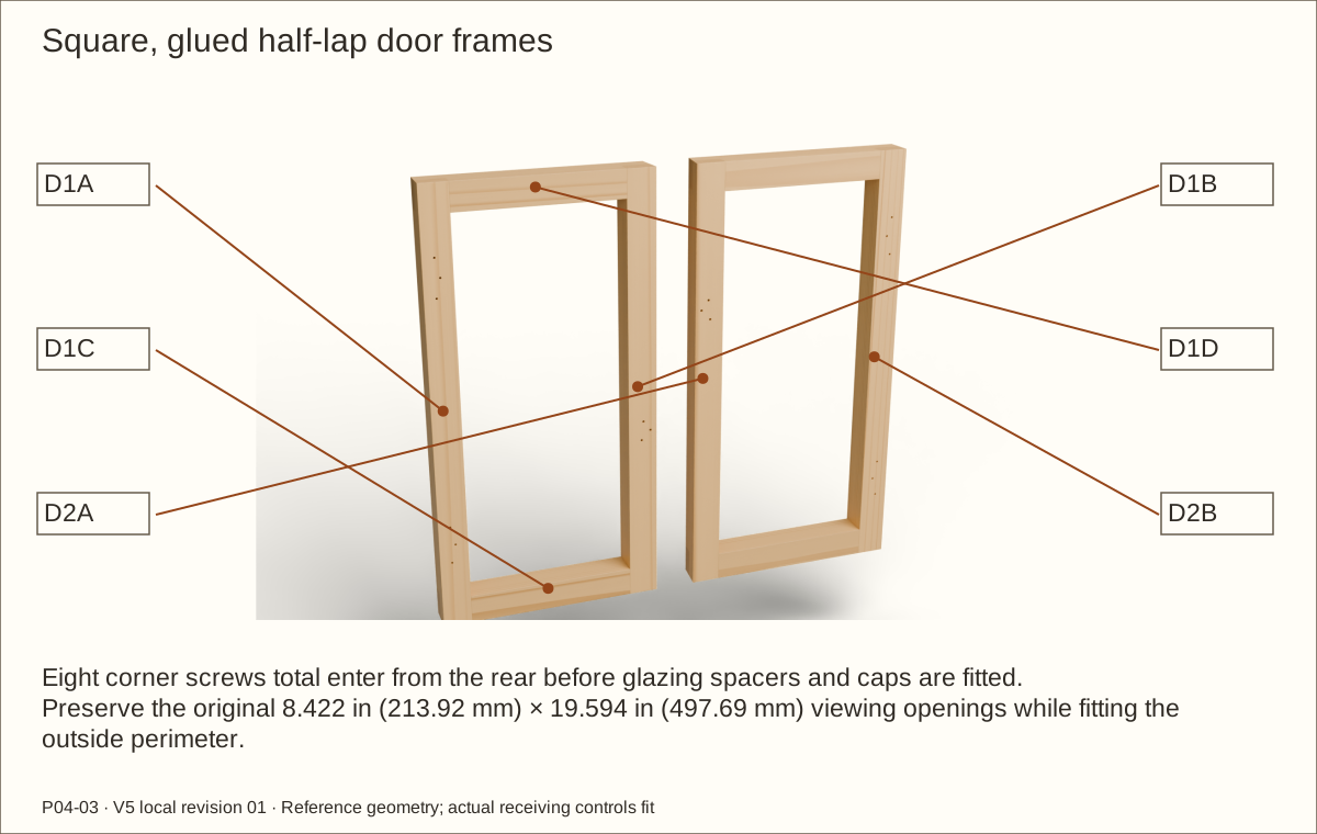
Glue the bare half-lap faces, clamp each frame flat and compare diagonals. Keep the inner opening datums unchanged.
Install the eight DOOR-LAP #8 × 1 1/4 in (31.75 mm) screws from the rear at the scheduled corner stations, with clearance through the rear member and a stopped pilot in the front member.
Remove squeeze-out from the future pane contact area. Check flatness again before the glue sets.
Check before continuing: Both square frames have fully seated joints and buried tips.
Required wait: Keep the specified clamps and no-stress wait; do not machine or hang an uncured joint.
Parts: D1A · Door 1 half-lapped stile; D1B · Door 1 half-lapped stile; D1C · Door 1 half-lapped rail; D1D · Door 1 half-lapped rail; F05 · Front centre stile
Tools / setup: Tape, square, caliper, pencil and the tools named in this operation
Before you begin: Do not simply veneer the source 1/8 in (3.18 mm) gaps; they have inadequate allowance.
Fit bare door gaps for the complete veneer
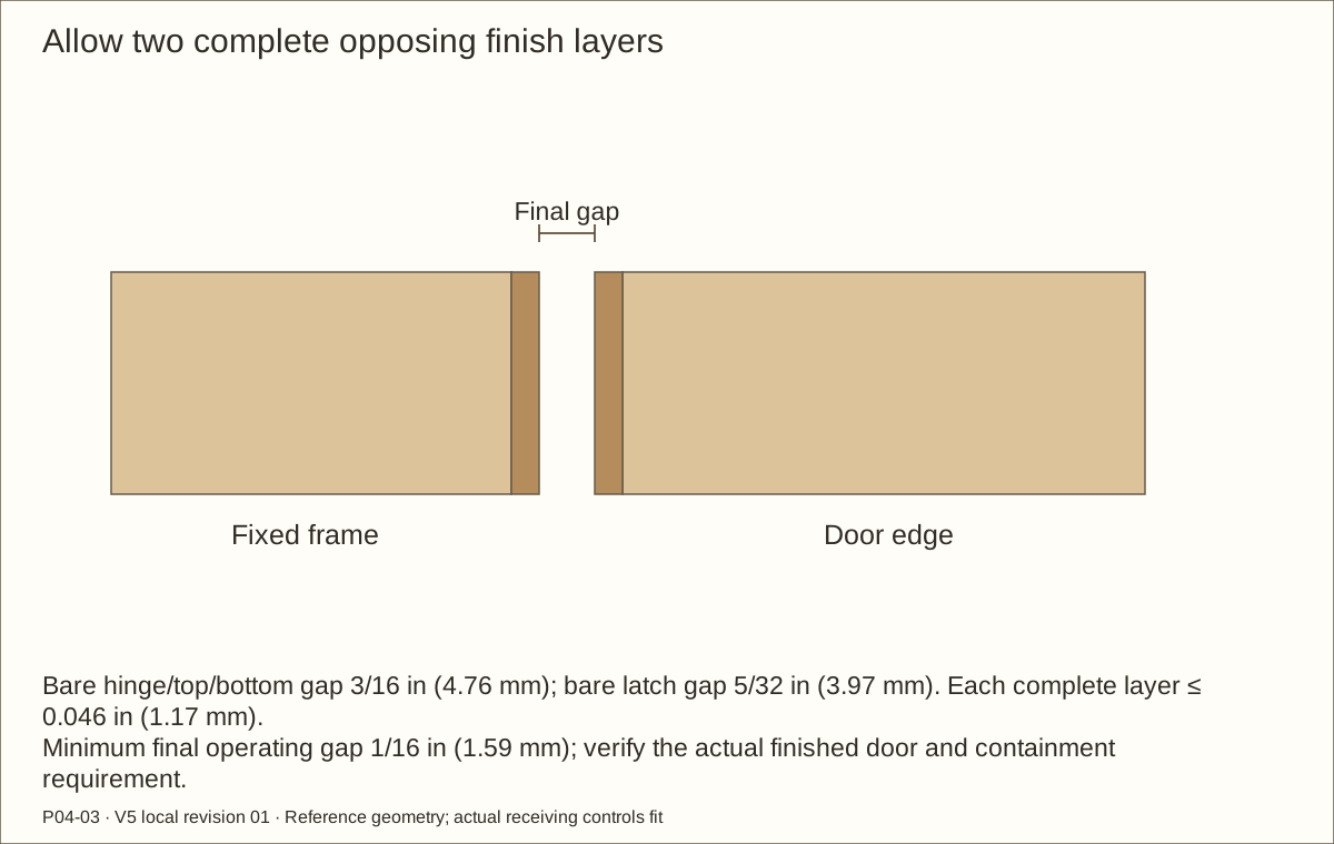
After curing, trim each original door by 1/16 in (1.59 mm) at its hinge edge and top/bottom, and 1/32 in (0.79 mm) at its latch edge. Preserve the original viewing opening and rear glazing datums.
Reference finished bare leaves are 11.32825 in (287.74 mm) wide × 22.469 in (570.71 mm) high. Fit to the actual frame: 3/16 in (4.76 mm) bare hinge/top/bottom gaps and 5/32 in (3.97 mm) bare latch gaps.
Two maximum 0.046 in (1.17 mm) opposing layers leave at least 0.06425 in (1.63 mm) at the latch. After full cure, verify every actual gap is at least 1/16 in (1.59 mm) and agrees with the species containment decision.
Check before continuing: Bare gaps allow the complete received finish without losing the viewing opening.
Parts: D1B · Door 1 half-lapped stile; D2A · Door 2 half-lapped stile
Tools / setup: Tape, square, caliper, pencil and the tools named in this operation
Bevel the rear latch edges
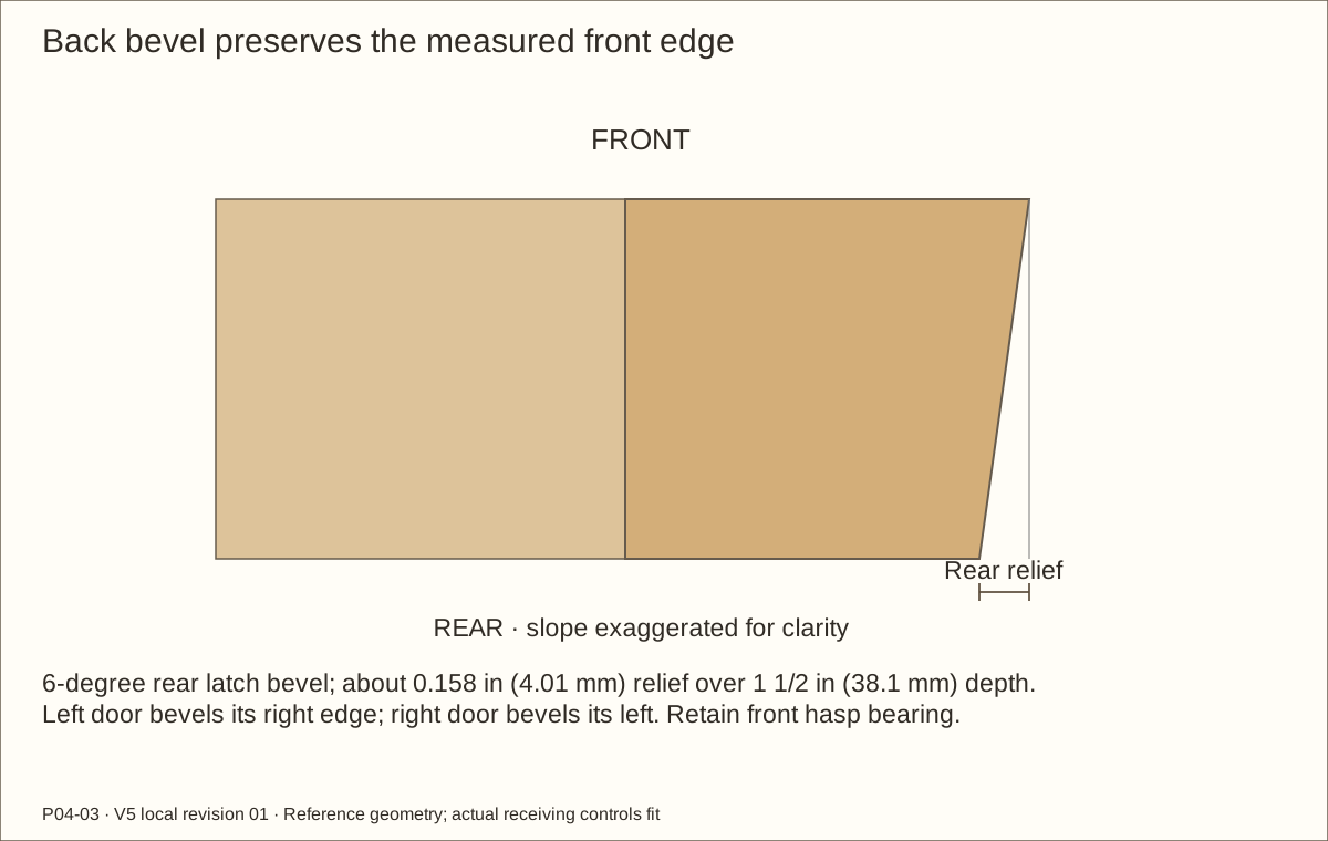
A back bevel slopes the rear edge inward while preserving the front edge. Set a trial 6-degree bevel on the LEFT door’s right edge and the RIGHT door’s left edge.
Over the 1 1/2 in (38.1 mm) depth this removes about 0.158 in (4.01 mm) at the rear. Keep the front measurement, half-lap fit, hasp bearing face and pane spacer datums intact.
Dry-swing the supported leaves on the accepted hardware. Cover the bevel with its own veneer strip later; do not wrap a thick piece around a sharp corner.
Check before continuing: Both latch edges clear through opening without shortening the front face.
Parts: Q1L · Door 1 separate spacer L; Q1R · Door 1 separate spacer R; B1L · Door 1 separate flat cap L; B1R · Door 1 separate flat cap R; G1 · Door 1 OPTIX pane
Tools / setup: Tape, square, caliper, pencil and the tools named in this operation
Before you begin: Do not use an incompatible cleaner, flame finishing or an unsupported cut that cracks acrylic.
Make the spacers, caps and acrylic panes
Cut Q1/Q2 spacer strips from 3/8 in (9.53 mm) square poplar and B1/B2 caps from 1/4 in (6.35 mm) pine lattice. Keep the left/right/top/bottom IDs; the vertical caps are 7/8 in (22.23 mm) wide and horizontal caps 3/4 in (19.05 mm) wide.
Each reference acrylic pane is 9.172 in (232.97 mm) wide × 20.344 in (516.74 mm) high × 0.22 in (5.59 mm) thick. Confirm the actual spacer opening and 1/8 in (3.18 mm) edge allowance before final cutting.
Keep the protective masking, use the acrylic maker’s supported cutting method and clean debris with compatible products. No screw hole is drilled through the pane.
Check before continuing: Both panes fit freely within their dry spacer frames.
Parts: Q1L · Door 1 separate spacer L; Q1R · Door 1 separate spacer R; B1L · Door 1 separate flat cap L; B1R · Door 1 separate flat cap R; B1B · Door 1 separate flat cap B; B1T · Door 1 separate flat cap T
Tools / setup: Tape, square, caliper, pencil and the tools named in this operation
Drill and trial the glazing cap stations
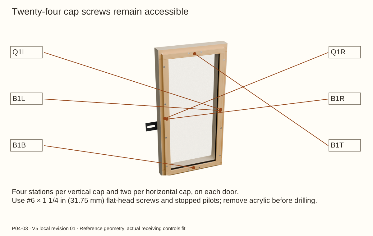
Lay the door flat and supported, rear upward. Dry-fit the spacers, actual pane and accepted rear EPDM strips. Fit caps onto the wood spacer faces.
Transfer the 24 GLAZE #6 × 1 1/4 in (31.75 mm) stations: four on each vertical cap, two on each horizontal cap. Drill with the pane removed; countersink only the wood cap.
Trial fit without glue. The cap should stop on its spacer with light cushion contact, a free pane edge and no bow; then label and remove the parts for later finishing.
Check before continuing: Caps are accessible and pane removal does not depend on cutting glue.
Tools / setup: Tape, square, caliper, pencil and the tools named in this operation
Cut the roof and side screen battens
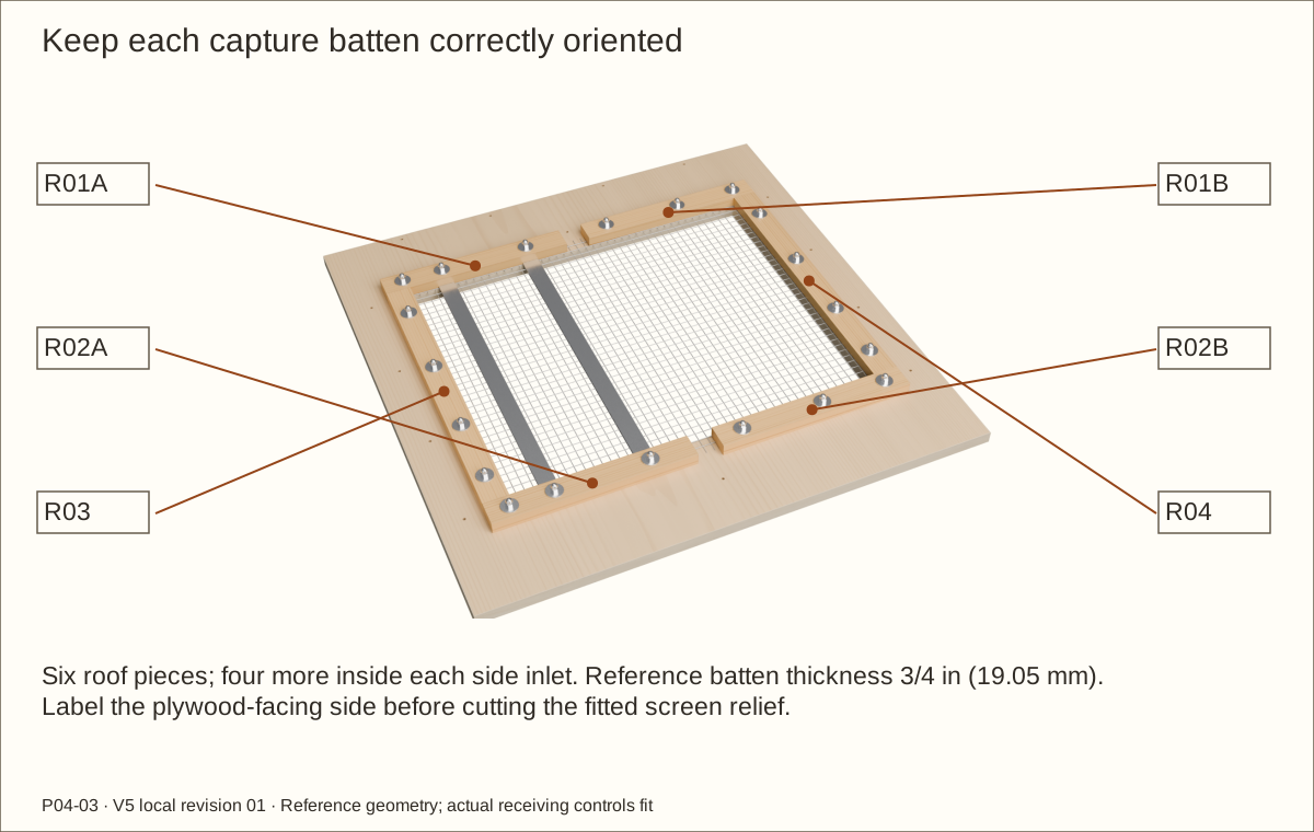
Cut six roof battens and four battens per side from 3/4 in (19.05 mm) pine. A batten is a narrow strip that traps the screen edge against the case.
Keep R01A/R02A beside the left steel support bay, R01B/R02B beside the right bay, and R03/R04 at the sides. Preserve the centre split around C11.
Dry-fit every batten against its own opening and mark the face toward the plywood. That face receives the controlled screen recess in the next operation.
Check before continuing: All capture pieces have the correct side, orientation and overlap.
23. Recess the screen while retaining wood bearing
Parts: R01A · Roof edge-capture batten; R03 · Roof edge-capture batten; V1B · Side inlet capture batten; V1F · Side inlet capture batten; C11 · Solid central roof rib
Tools / setup: Stopped router or suitable milling setup, clamps, backer, caliper and actual mesh
Before you begin: Do not route away the bearing land or assume a reference pocket proves clamp strength.
Recess the screen while retaining wood bearing
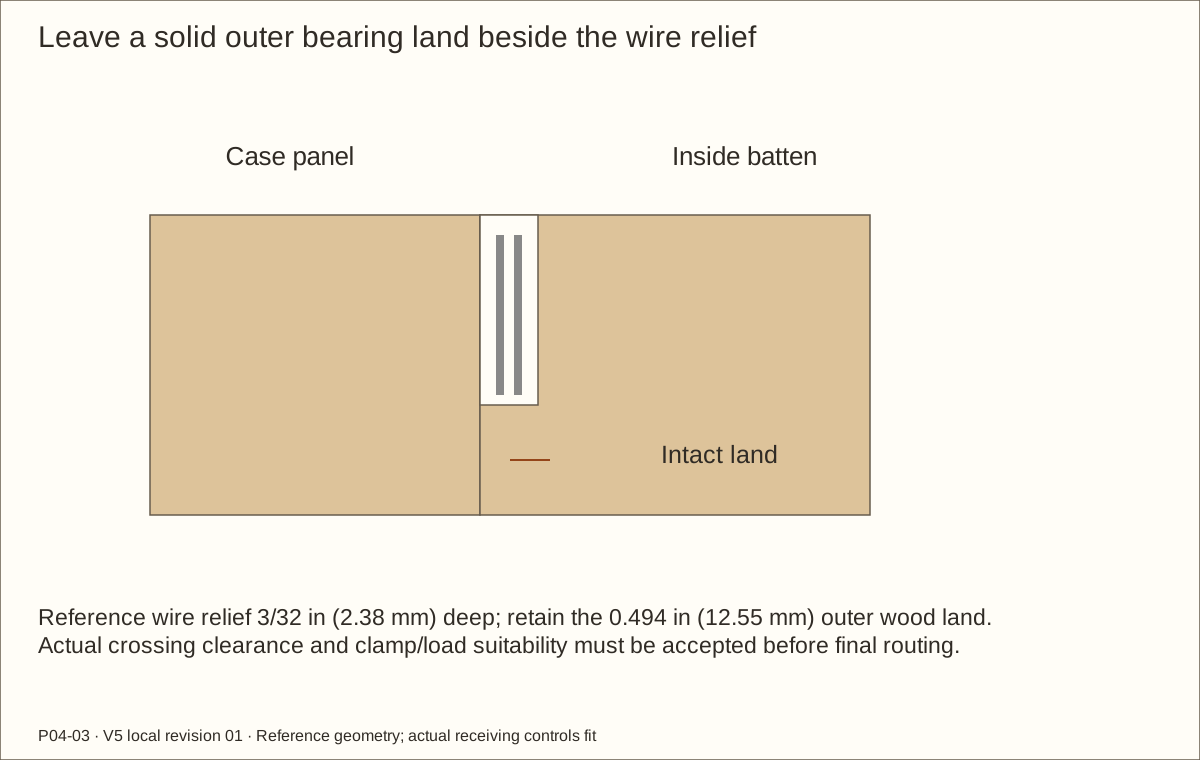
A recess is a shallow pocket. On the plywood-facing side of each batten, relieve the screen footprint to the accepted actual crossing thickness; the reference depth is 3/32 in (2.38 mm).
Keep the outer 0.494 in (12.55 mm) reference land intact. That land bears on the plywood; the recessed zone contains the wire without using the screws to crush welds. The reference edge relief is 0.006 in (0.15 mm).
Fit C11’s own mesh relief and the roof’s steel pockets separately. Trial actual wire and plywood before repeating the routing on final battens.
Check before continuing: Wood lands seat fully and the screen remains captured with no sharp loose edges.
Parts: M01 · Roof screen blank; VM1 · Side inlet screen blank; VM2 · Side inlet screen blank
Tools / setup: Tape, square, caliper, pencil and the tools named in this operation
Cut and contain the three screens
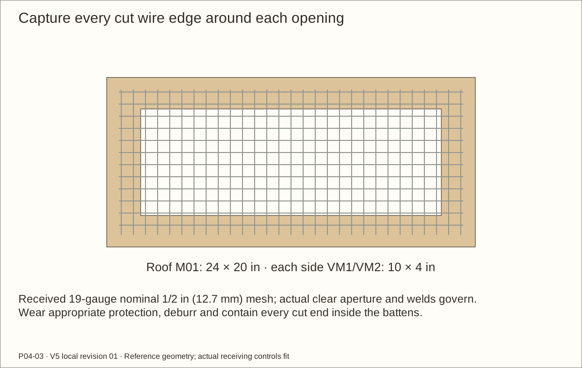
Cut roof M01 at 24 in (609.6 mm) × 20 in (508 mm) and side VM1/VM2 at 10 in (254 mm) × 4 in (101.6 mm), using the accepted received cloth and eye/hand protection.
Deburr and keep every cut wire edge within the batten capture footprint. Do not leave pointed ends projecting into an animal or maintenance path.
Register the grid to the drilling drawing. The 1/2 in (12.7 mm) centre spacing and 0.041 in (1.04 mm) wire are modeling references; measure the actual grid, welds and clear aperture before drilling.
Check before continuing: All screen edges are safely captured and the actual grid registration is recorded.
Before you begin: A strip and a geometric fixture fit do not establish a load or temperature rating.
Cut, deburr and seat the two steel strips
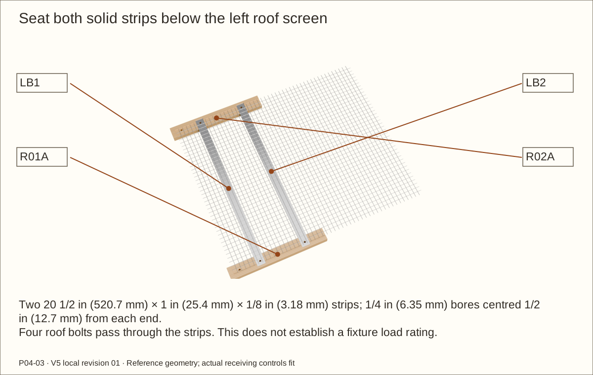
Cut each solid steel strip 20 1/2 in (520.7 mm) long × 1 in (25.4 mm) wide × 1/8 in (3.18 mm) thick. The legacy product URL contains “Slotted”, but the selected 11653 stock is solid flat bar.
Clamp and drill two 1/4 in (6.35 mm) bores per strip, centred across its width and 1/2 in (12.7 mm) from each end. Deburr both faces and ends completely.
Fit the strip ends into the matching front/rear roof pockets. Their original absolute support centres remain 6 1/4 in (158.75 mm) and 11 3/4 in (298.45 mm) from LEFT; all four roof fixing axes must pass freely.
Check before continuing: Both strips seat fully with four matching axes and no sharp corners.
Parts: SP-H1-1-fixed · Rigid full-leaf bearing pad H1-1 fixed; SP-H1-1-moving · Rigid full-leaf bearing pad H1-1 moving
Tools / setup: Tape, square, caliper, pencil and the tools named in this operation
Make eight matched hinge bearing pads
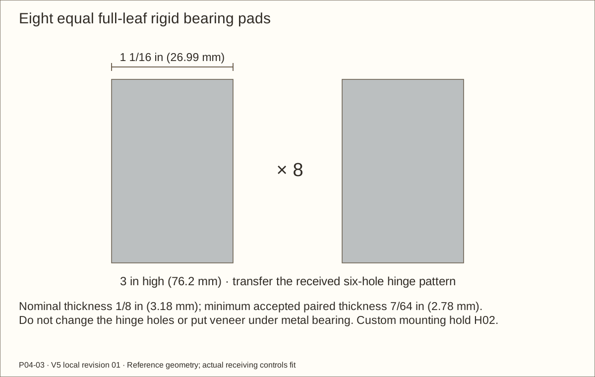
Cut eight 3 in (76.2 mm) × 1 1/16 in (26.99 mm) pads from solid nominal 1/8 in (3.18 mm) aluminium. Keep matched pairs; minimum accepted actual thickness is 7/64 in (2.78 mm).
Deburr all edges, check flatness and transfer the received hinge holes. Use clearance holes through the pads; do not change the hinge holes.
Trial full metal-to-bare-wood bearing without bridging any door gap. Keep adhesive and veneer out of these seats. Custom mounting strength and corrosion suitability require H02 acceptance.
Check before continuing: Every pad pair matches and the actual screws seat correctly.
Parts: P01 · Continuous floor; P03 · Left side with lower inlet; P04 · Right side with lower inlet; C03 · Solid side bearing cleat; C04 · Solid side bearing cleat; C07 · Solid front/back ledger; C08 · Solid front/back ledger
Tools / setup: Tape, square, caliper, pencil and the tools named in this operation
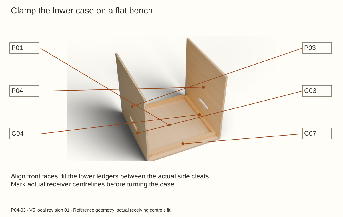
Dry-fit the floor, sides and lower supports
On a padded flat bench, position the sides on the floor and place the lower side cleats and front/rear ledgers between the named members.
Clamp without pulling a bowed panel into alignment. Check both front datums, side height chains and the 30 in (762 mm) bare width/depth.
Mark the actual receiver centre lines from inside. Use the current station drawing for the exterior drill direction and retain those labels during turning.
Check before continuing: The dry lower case sits level and the cleat/ledger joints contact correctly.
Parts: F01 · Front outer stile; F02 · Front outer stile; F03 · Front sill; F04 · Front header; F05 · Front centre stile; F06 · Rear centre stile
Tools / setup: Tape, square, caliper, pencil and the tools named in this operation
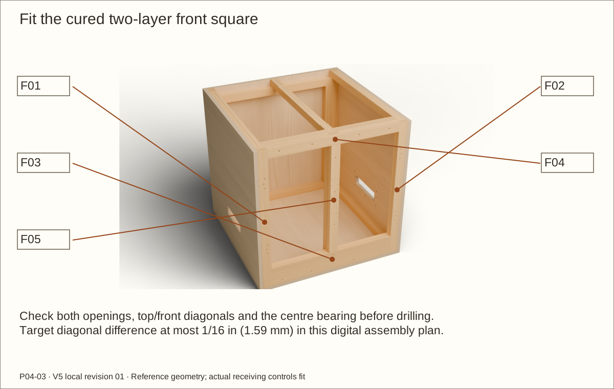
Install the cured fixed front frame
Clamp the cured two-layer frame into the open front with the designated outer faces flush.
Check both door openings and the centre support alignment. Compare front and top diagonals; use a 1/16 in (1.59 mm) maximum difference as the assembly target before drilling.
Rehearse removal and fitting of the roof and both doors. Do not hide a skewed case by changing one leaf or tightening an opposing screw.
Check before continuing: The front remains flat, square and aligned with the actual support members.
Parts: P01 · Continuous floor; P03 · Left side with lower inlet; P04 · Right side with lower inlet; P05 · Back; F03 · Front sill
Tools / setup: Tape, square, caliper, pencil and the tools named in this operation
Before you begin: The workshop schedule distinguishes every screw length and direction; do not substitute by appearance.
Drill and screw the case in the planned order
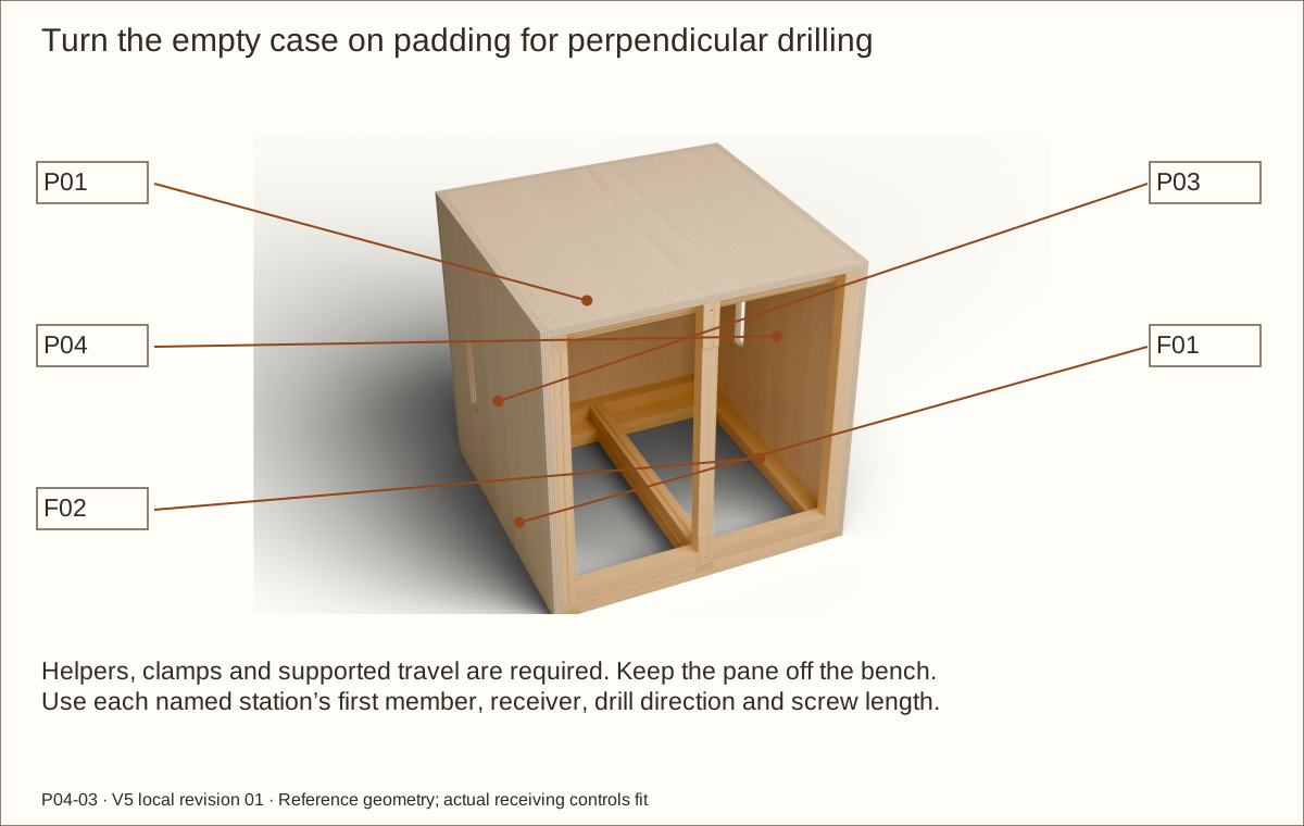
With help, turn the EMPTY clamped assembly onto padding as needed to drill perpendicular to the actual faces. Keep panes and loose hardware off the bench.
Follow each named station group: side cleats/back/front, back corners/ledgers, front ledgers/centre, floor side/ledger, rear posts and rib. Clear the first member and stop the pilot in its actual receiver.
Install the specified #8 × 1 3/4 in (44.45 mm) or #8 × 2 1/2 in (63.5 mm) screw at that station. Check squareness as you tighten; use hand control for final seating. Preserve the removable roof.
Check before continuing: All case stations match their named receivers, with no split wood or exposed tips.
Parts: P02 · Roof with upper exhaust; C05 · Solid side bearing cleat; C06 · Solid side bearing cleat; C11 · Solid central roof rib
Tools / setup: Tape, square, caliper, pencil and the tools named in this operation
Trial the roof as a removable assembly
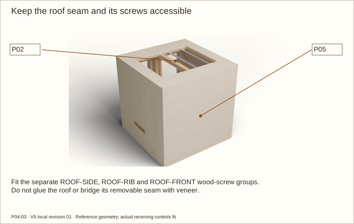
Place the roof on the dry case and transfer the ROOF-SIDE, ROOF-RIB and ROOF-FRONT station groups from the actual supports.
Use the specified #8 × 1 3/4 in (44.45 mm) screws, with clear roof holes, controlled head seats and stopped receiver pilots. Check the panel is flat without forcing it down.
Remove the roof again for screen work. Do not glue it to the case, and keep later veneer pieces separate at this service seam.
Check before continuing: The roof can be lifted away after its accessible screws are removed.
32. Transfer side screen axes through open wire cells
Parts: P03 · Left side with lower inlet; VM1 · Side inlet screen blank; V1B · Side inlet capture batten; V1T · Side inlet capture batten; V1F · Side inlet capture batten; V1R · Side inlet capture batten
Tools / setup: Tape, square, caliper, pencil and the tools named in this operation
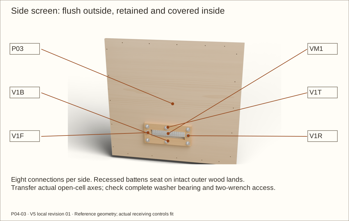
Transfer side screen axes through open wire cells
With the side accessible and supported, seat the actual screen and four recessed inside battens on their intact wood lands.
Transfer the eight axes per side from the current drawing and actual grid. Keep every 1/4 in (6.35 mm) bore clear of wires and welds; do not cut a wire to force alignment.
Check a full 1 in (25.4 mm) inside washer bearing circle and room for the actual locknut, cover and driver/socket. Record any required change before repeating on the other side.
Check before continuing: All 16 side stations pass through open cells with full wood and washer bearing.
33. Fit flush heads and covered inside side fixings
Parts: P03 · Left side with lower inlet; V1B · Side inlet capture batten; VM1 · Side inlet screen blank
Tools / setup: Stopped drill/countersink, caliper, thread-matching nut, metal-cutting/deburring tools, driver and two suitable wrenches
Before you begin: Do not bottom the closed cover, crush wire or use an untested torque value. Resolve H03 before dependent installation.
Fit flush heads and covered inside side fixings
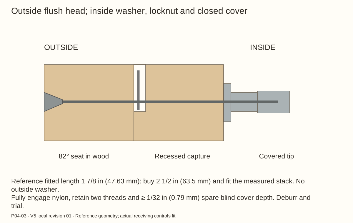
Drill through the supported stack, remove the metal/mesh and form only the outside 82-degree wood seat. Test the actual head at the bare wood plane with no outside washer.
Refit screen and battens. Inside, fit one washer and nylon-insert locknut per bolt, then a closed metal cover over the remaining thread.
Purchase 2 1/2 in (63.5 mm) bolts and fit to the actual stack. The reference final length here is 1 7/8 in (47.63 mm). Fully engage the nylon, leave at least two complete threads beyond it, and retain at least 1/32 in (0.79 mm) spare blind cover depth after deburring.
Check before continuing: Wood lands seat, outer heads are flush and all inside thread ends remain covered.
Tools / setup: Tape, square, caliper, pencil and the tools named in this operation
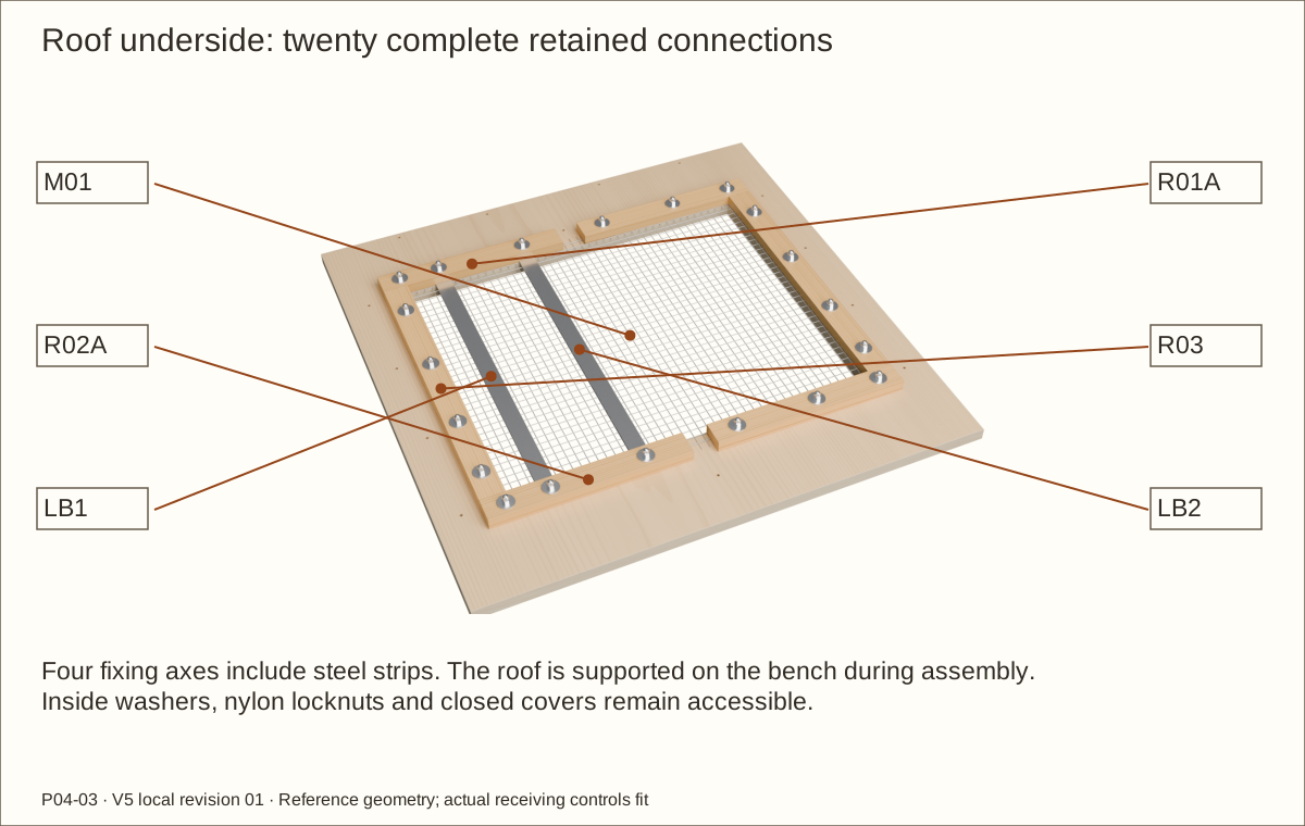
Assemble the roof screen and steel supports
Support the roof upside down. Fit the two deburred steel strips in their own pockets, the screen against the roof underside and all six recessed battens.
Transfer all 20 axes through the actual grid and receiver lands. Four also pass through the steel bores. Confirm the central rib relief will clear when the roof returns to the case.
Use the same flush-outside and retained-covered-inside fixing sequence, with received-stack bolt fitting. Check the underside from every approach for wrench access and sharp ends.
Check before continuing: The roof assembly is square, independently removable and has 20 complete inside-covered connections.
Parts: H1-1_fixed · 1798A21 fixed leaf with knuckles; H1-1_moving · 1798A21 moving leaf with knuckles; D1A · Door 1 half-lapped stile; F01 · Front outer stile
Tools / setup: Tape, square, caliper, pencil and the tools named in this operation
Hang and align the supported bare doors
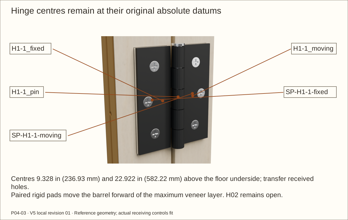
Keep the original hinge centres at 9.328 in (236.93 mm) and 22.922 in (582.22 mm) above the floor underside. Do not remeasure the original offset from the newly trimmed door ends.
Clamp both leaves at the accepted bare gaps with a helper supporting their weight. Fit matched pads and received hinges to bare seats; transfer and drill the actual 24 #8 × 1 1/4 in (31.75 mm) screw stations.
Check that pins align, leaves seat flat and neither door drops or rubs through its supported swing. Remove a misaligned hinge and correct the fit; do not bend it by tightening.
Check before continuing: Both doors swing with sound support, positive gaps and buried screw points.
Tools / setup: Tape, square, caliper, pencil and the tools named in this operation
Before you begin: Padlocks are optional and not included. Do not use the drawing as a drill template or force the nominal flap through the swivel.
Fit the two independent swivel hasps
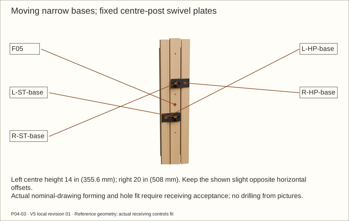
Fit the left swivel centre at 14 in (355.6 mm) and right at 20 in (508 mm) above the floor underside. Preserve the small opposite horizontal offsets shown in the drawing; the actual plate footprints and holes govern.
Place each narrow hinged base on its MOVING door stile and its square swivel plate on FIXED F05. Use seven received-transferred #10 × 5/8 in (15.88 mm) screws per complete hasp.
Trial the actual complete plates, countersinks and sound edge margins. Turn the swivel to align with the flap slot, lift the flap fully clear, then open that door. Reverse to close by hand.
Check before continuing: Each door latches independently with no key and no unsupported plate or screw.
Parts: H1-2_pin · 1798A21 removable pin reference; G1 · Door 1 OPTIX pane; B1L · Door 1 separate flat cap L; P02 · Roof with upper exhaust
Tools / setup: Tape, square, caliper, pencil and the tools named in this operation
Rehearse pin, pane and roof removal
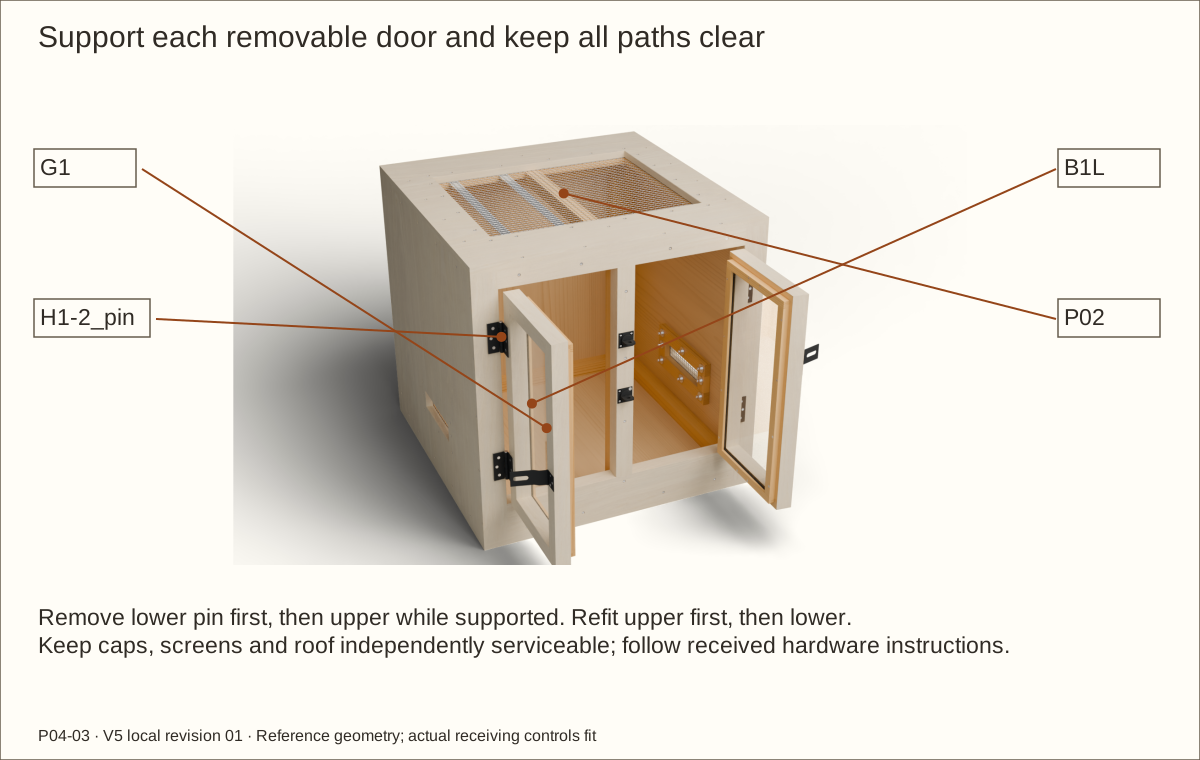
Support one open door with a helper. Remove the lower hinge pin first, then the upper, following the received hinge instructions and actual tool path. Move the freed leaf forward; never let it hang from one pin.
On a padded bench, support the pane, unscrew its rear caps and lift away loose rear strips and pane without prying. Keep the spacers and datums labeled.
Remove accessible roof screws and lift the roof clear. Check inward side-batten removal and all tool paths before finishing. Rehang by engaging the upper pin first while supported, then the lower.
Check before continuing: Every service route works without cutting glue, damaging the pane or forcing a part.
Parts: P01 · Continuous floor; P02 · Roof with upper exhaust; D1A · Door 1 half-lapped stile; D1B · Door 1 half-lapped stile; G1 · Door 1 OPTIX pane
Tools / setup: Tape, square, caliper, pencil and the tools named in this operation
Before you begin: No wet coating or adhesive may contact the pane or its unbonded strips.
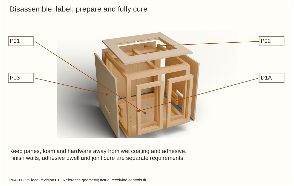
Disassemble and prepare the finish surfaces
Label and remove doors, hinges, pads, hasps, panes, foam, screens and removable captures. Keep hardware sets together and protect the acrylic masking.
Remove glue residue, lightly sand as required by the coating and veneer instructions and clean all dust with compatible methods. Do not round joint datums or change fitted gaps.
Mark bare metal-bearing footprints and service seats. Mask glue/bearing areas where required by the accepted construction and coating system.
Check before continuing: All surfaces are clean, labeled and ready for the accepted finish system.
Parts: P02 · Roof with upper exhaust; P03 · Left side with lower inlet; D1A · Door 1 half-lapped stile
Tools / setup: Tape, square, caliper, pencil and the tools named in this operation
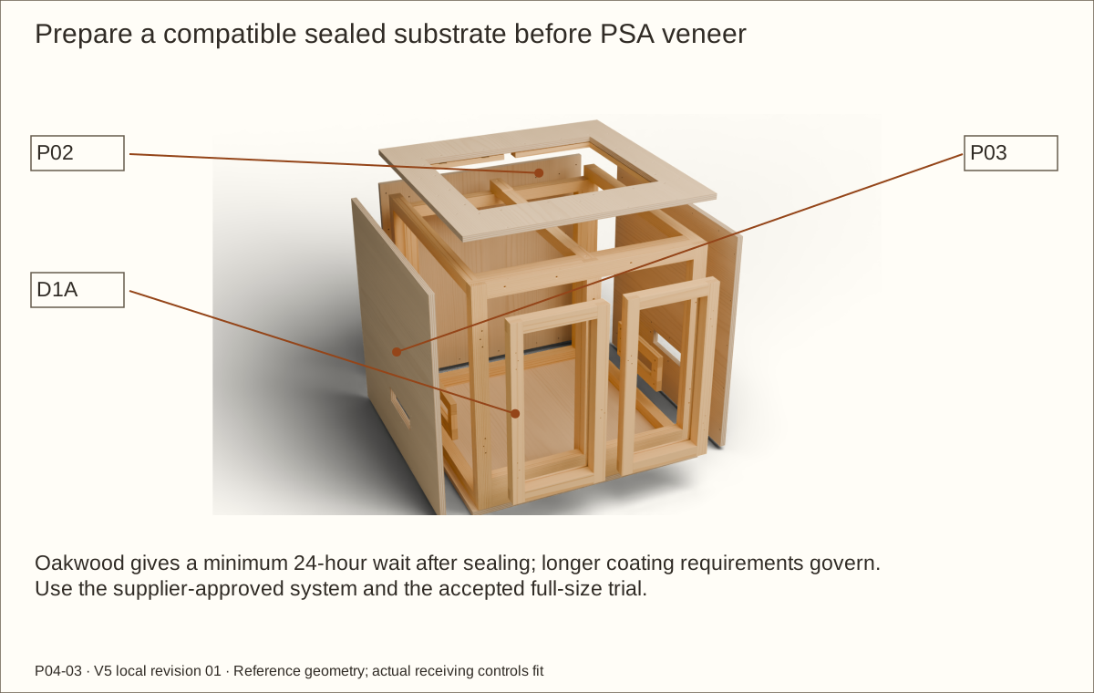
Seal the veneer substrate and wait
Follow the accepted PSA veneer supplier’s porous-substrate preparation. Oakwood’s guide calls for sealing porous wood before its PSA application.
Use the approved compatible sealer/topcoat combination and the thickness already accepted in the full-size trial. Keep metal bearing footprints and fastener service openings free of veneer.
Check the surface is flat, clean and fully suitable for adhesion before applying any veneer. A dry-feeling surface alone does not resolve compatibility or cure.
Check before continuing: Supplier-approved surface preparation and the recorded wait are complete.
Required wait: Oakwood states at least 24 hours after sealing; a longer coating or supplier requirement still governs.
40. Fit separate veneer pieces to all exposed edges
Parts: P01 · Continuous floor; P02 · Roof with upper exhaust; P03 · Left side with lower inlet; D1A · Door 1 half-lapped stile; D1B · Door 1 half-lapped stile
Tools / setup: Tape, square, caliper, pencil and the tools named in this operation
Before you begin: Use protected hand placement and a supported sharp cutter; never slice toward the hand holding a narrow strip.
Fit separate veneer pieces to all exposed edges
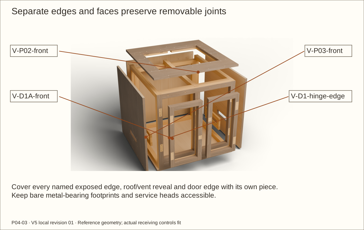
Use the grain-oriented rough pieces for roof/floor edges, side front/back edges, roof and vent reveals, fixed door-opening reveals and door edges.
Dry-place and label each piece before exposing adhesive. Use separate strips at square corners, the sloped latch edge and each removable seam; do not bridge from roof to side or door to frame.
Apply the accepted pressure along the grain, working from the centre outward. Trim in controlled scoring passes on support and ease only sharp veneer arrises.
Check before continuing: All visible edges have matching coverage without changing the service seams.
Required wait: Follow the accepted adhesive application and dwell requirements.
Parts: P01 · Continuous floor; P02 · Roof with upper exhaust; P03 · Left side with lower inlet; P04 · Right side with lower inlet; P05 · Back
Tools / setup: Tape, square, caliper, pencil and the tools named in this operation
Cover the roof, underside and exterior faces
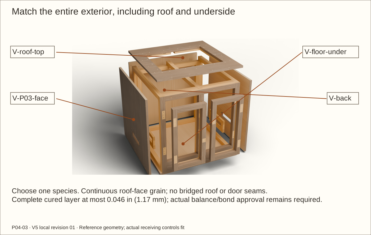
Apply the chosen species to the complete roof top, floor underside, side faces, back, fixed front faces and door faces using the assigned grain directions.
Keep one continuous roof-face grain layout around its aperture. Keep separate door rails and stiles and fully expose the named hardware seats and service heads.
Press and trim according to the accepted system. Inspect each corner, opening reveal and underside for exposed plywood, loose edges or a bridged removable joint.
Check before continuing: The exterior looks uniform and the agreed complete layer stays within its fit allowance.
Parts: P02 · Roof with upper exhaust; P03 · Left side with lower inlet; F05 · Front centre stile; D1A · Door 1 half-lapped stile
Tools / setup: Tape, square, caliper, pencil and the tools named in this operation
Apply the specified clear finish
Use the accepted Varathane Triple Thick water-based satin system in the maker’s 60–90°F (15.6–32.2°C) application range and below 85% relative humidity, with required ventilation and protection.
Apply the specified coat and film thickness to the intended surfaces; the reference dry film is 0.003 in (0.08 mm). The conservative quantity includes faces, exterior preseal, veneer topcoat and trial reserve.
Keep the accepted face balance and avoid pooled finish at gaps, bearing seats and glazing contact areas. An extra coat changes thickness and purchasing allowance; recheck before adding it.
Check before continuing: Finish coverage and conditions are recorded, with no blocked seats or gaps.
Required wait: Maker reference: at least 2 hours before recoating, 48 hours before light use and 7 days to full cure at 70°F (21.1°C)/50% humidity. Cooler or more humid conditions extend times; full cure is required before glazing and use.
Parts: D1A · Door 1 half-lapped stile; D1B · Door 1 half-lapped stile; F05 · Front centre stile; P02 · Roof with upper exhaust
Tools / setup: Tape, square, caliper, pencil and the tools named in this operation
Inspect cured layers and finish the final fit
After the required cure and adhesive dwell, measure the actual complete veneer layer and compare the full-size trial.
Dry-fit the doors, pads, hasps, roof and captures. Verify at least 1/16 in (1.59 mm) final door clearance everywhere and record the actual values; verify every covered reveal still admits its intended part.
If a gap closes, a bond lifts, a face bows or a plate loses bearing, stop and revise the affected geometry. Do not sand through veneer at random or force parts with screws.
Check before continuing: The cured finish and the actual fitted geometry agree.
Parts: M01 · Roof screen blank; VM1 · Side inlet screen blank; VM2 · Side inlet screen blank; LB1 · Steel strip below left lamp area; LB2 · Steel strip below left lamp area; P02 · Roof with upper exhaust
Tools / setup: Tape, square, caliper, pencil and the tools named in this operation
Reinstall screens, supports and roof
Refit the labeled screens, recessed battens and steel supports on clean wood bearing lands. Keep the received, fitted bolt sets with their original stations.
Seat all 36 flush heads, inside washers and nylon locknuts; confirm closed covers have spare blind depth and remain secure. Use the accepted hand-controlled assembly, not an invented torque.
Refit the removable roof using its separate wood screws. Verify its panel sits flat, rib relief clears and every service head remains accessible.
Check before continuing: No wire point, projecting outside nut or uncovered inside thread remains.
Parts: H1-1_fixed · 1798A21 fixed leaf with knuckles; H1-1_moving · 1798A21 moving leaf with knuckles; D1A · Door 1 half-lapped stile; D2B · Door 2 half-lapped stile
Tools / setup: Tape, square, caliper, pencil and the tools named in this operation
Rehang and operate both finished doors
Refit the bare bearing pads, hinges and hasps to their received-transferred holes. Support each leaf, insert the upper pin first, then the lower, without hammering a misaligned assembly.
Release each swivel and flap completely before moving its door. Open and close each through its intended range alone, then with the other open; check the actual hasp and hand paths.
Confirm final gaps, pin extraction space and independent hand-operated latching. Mark any door stop or user handling requirement established by the physical trial.
Check before continuing: Both finished doors operate and remain removable without rubbing or force.
46. Fit clean panes, rear strips and removable caps
Parts: G1 · Door 1 OPTIX pane; G2 · Door 2 OPTIX pane; E1L · Door 1 plain EPDM rear cushion L; E1B · Door 1 plain EPDM rear cushion B; B1L · Door 1 separate flat cap L; B1B · Door 1 separate flat cap B
Tools / setup: Tape, square, caliper, pencil and the tools named in this operation
Before you begin: If it bows or rattles, resolve the actual stack and supplier advice; do not use extra torque as a correction.
Fit clean panes, rear strips and removable caps
Remove each supported door using the rehearsed pin sequence and lay it on a clean padded bench. Support the pane; remove masking after machining and cleanup. Use only acrylic-compatible cleaners.
Fit the actual pane inside the retained spacer opening with 1/8 in (3.18 mm) edge gaps. Place the accepted plain EPDM strips behind it, with no adhesive to the pane and no extra stacked layers.
Seat each labeled cap on its spacer and gently tighten the specified #6 screws. Check for pane bow, rattle, debris and edge contact. Rehang the glazed door with a helper, upper pin first, then lower; repeat the operation checks.
Check before continuing: Each pane has light cushion contact and can be removed without cutting adhesive.
Tools / setup: Tape, square, caliper, pencil and the tools named in this operation
Before you begin: Do not place a fixture on unsupported mesh. The listed electrical maximum is not a recommended operating wattage or a thermal clearance.
Set the optional fixture only after receiving checks
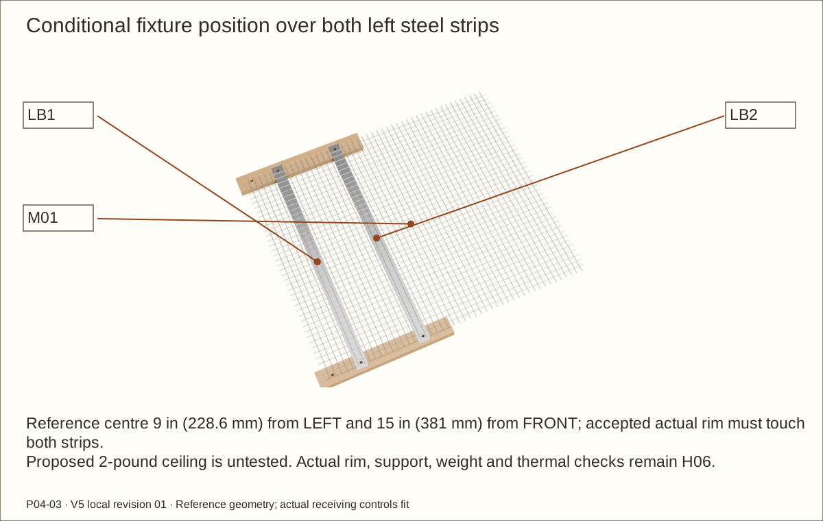
This design provides one optional external fixture location centred 9 in (228.6 mm) from LEFT and 15 in (381 mm) from FRONT. Its rigid flat rim must contact both steel strips through the screen.
The source geometry allows a 5 1/2 in (139.7 mm)–6 in (152.4 mm) rim and at most 6 in (152.4 mm) overall diameter. Its proposed 2-pound (0.91 kg) assembled-weight ceiling is untested; weigh the actual fixture and bulb and obtain support/load acceptance.
Follow the exact fixture/bulb instructions for secure support, electrical limits and heat clearances. The right roof bay remains clear of heat equipment; establish the required shade and temperature gradient.
Check before continuing: Received fixture geometry, weight, secure support and commissioning plan are accepted.
Parts: P01 · Continuous floor; P03 · Left side with lower inlet; P04 · Right side with lower inlet; M01 · Roof screen blank
Tools / setup: Tape, square, caliper, pencil and the tools named in this operation
Before you begin: This dry indoor shell is not a water-holding, lined, outdoor, structural or animal-safety certification.
Commission the empty finished enclosure
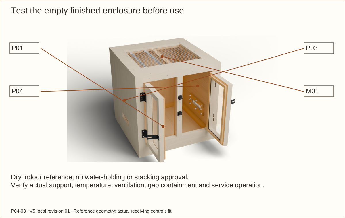
Before animals, complete the recorded species-specific checks for opening/mesh containment, ventilation, heat gradient, humidity, cleaning and door handling.
Keep dry substrate no higher than 3 in (76.2 mm) above the inside floor and a clear 2 in (50.8 mm) zone around each side inlet, unless an accepted coordinated species design requires a revision.
Verify the full base support and actual loaded stability. Run the actual equipment under supervision according to maker and qualified guidance, measuring all critical surfaces and air zones.
Check before continuing: The physical commissioning record is complete and accepted.
Parts: P02 · Roof with upper exhaust; G1 · Door 1 OPTIX pane; H1-2_pin · 1798A21 removable pin reference
Tools / setup: Tape, square, caliper, pencil and the tools named in this operation
Record inspection and repeatable maintenance
Record actual material gauges, final gaps, fitted fixing lengths, suppliers, cure dates, assembled weight and all accepted hold decisions.
Inspect pins, screws, caps, bond edges, pane contact, wire edges and support during cleaning. Remove animals and disconnect/cool equipment before maintenance.
Use the demonstrated roof, inward screen-batten, supported door and pane removal paths. Recheck operation and containment after service; preserve this revision with its evidence and any recorded substitution.
Check before continuing: Maintenance can be repeated without guessing the construction or losing its record.
Choose ONE veneer species: two 48 × 96 in (1219.2 × 2438.4 mm) sheets. Trial stock is included. FINISH is a two-quart-can pack. Resolve H01–H06 before dependent work. No purchase or address-specific stock check has been made.
Two allocated sheets. Reference actual thickness 0.703 in (17.86 mm); the listing also has a conflicting 3/4 in (19.05 mm) minimum field. Measure every received sheet; revise dependent fits together.
Four 72 in (1828.8 mm) × 7 1/4 in (184.15 mm) × 3/4 in (19.05 mm) boards include a dedicated trial board. Front layers and screen captures follow this revision’s layouts; caps use separate bought-thickness lattice.
Two 24 in (609.6 mm) × 18 in (457.2 mm) × 0.22 in (5.59 mm) sheets. Each pane is 9.172 in (232.97 mm) × 20.344 in (516.74 mm) with 1/8 in (3.18 mm) edge clearance. Keep free, unbowed and removable; confirm actual gauge, cleaning and temperature limits.
Materials and hardware · continued
Choose ONE veneer species: two 48 × 96 in (1219.2 × 2438.4 mm) sheets. Trial stock is included. FINISH is a two-quart-can pack. Resolve H01–H06 before dependent work. No purchase or address-specific stock check has been made.
One 16 US fluid-ounce (473 mL) bottle provision for the front lamination, door laps and trials. Actual spread/waste governs. Apply above 47°F (8.3°C); follow maker working time and clamping conditions. No stress for at least 24 hours.
One 36 in (914.4 mm) × 60 in (1524 mm) roll. Reference 1/2 in (12.7 mm) pitch and 0.041 in (1.04 mm) wire do not guarantee received aperture. All 36 fixing axes must clear wires and welds; contain every cut edge.
Seven 1 1/2 in (38.1 mm)-square × 96 in (2438.4 mm) sticks include a dedicated complete-door trial stick. Fit bearing posts to actual gaps. No structural grade or load rating is inferred.
Materials and hardware · continued
Choose ONE veneer species: two 48 × 96 in (1219.2 × 2438.4 mm) sheets. Trial stock is included. FINISH is a two-quart-can pack. Resolve H01–H06 before dependent work. No purchase or address-specific stock check has been made.
Ninety-four case/roof stations plus eight trial screws; two 75-count boxes. Roof remains removable. Actual stock, pilot and edge margins govern.
Materials and hardware · continued
Choose ONE veneer species: two 48 × 96 in (1219.2 × 2438.4 mm) sheets. Trial stock is included. FINISH is a two-quart-can pack. Resolve H01–H06 before dependent work. No purchase or address-specific stock check has been made.
Twenty-four rear cap stations plus eight trial screws; four 10-count packs. Drill with acrylic removed; cap seats on the wood spacer. Current listing specifies interior use.
CAP-LATTICE · RELIABILT 265 unfinished pine lattice, actual 1/4" × 1 3/4" × 96" Direct product listing
Two 96 in (2438.4 mm) lengths, reference 1/4 in (6.35 mm) × 1 3/4 in (44.45 mm) section. Rip to the named cap widths using supported long stock. Listing does not claim moisture resistance.
FINISH · Varathane Triple Thick clear satin polyurethane, two 1-quart cans Direct product listing
Four US quarts (3.79 L): two two-can packs. This revision allows 169.837 sq ft (15.78 m²), including exterior preseal, veneer topcoat, trials and 15% reserve, at 50 sq ft/quart (4.91 m²/L). Extra coats require recalculation. Cure and exposure approval remain separate.
Materials and hardware · continued
Choose ONE veneer species: two 48 × 96 in (1219.2 × 2438.4 mm) sheets. Trial stock is included. FINISH is a two-quart-can pack. Resolve H01–H06 before dependent work. No purchase or address-specific stock check has been made.
Product
Model and quantities
Fit / purchase condition
SPACER · Madison Mill 3/8-inch square solid poplar, 36-inch stick Direct product listing
Four square 3/8 in (9.53 mm) × 36 in (914.4 mm) solid-poplar sticks. Verify square profile and actual gauge; fitted spacer depth governs the cured glazing stack.
Plain strip, free 3/16 in (4.76 mm) thickness × 1/4 in (6.35 mm) width. Reference installed thickness 0.155 in (3.94 mm) gives 17.33% compression before coating allowances; actual cured trial controls contact. No clamping-force rating. Two 120 in (3048 mm) rolls include 12 in (304.8 mm) of trial stock.
Four complete removable-pin 1798A21 hinges; two pairs. Match the actual 24 flat-head screws and eight rigid pads. Door latch bevel is 6 degrees. Pin extraction, custom mounting and capacity remain H02.
Materials and hardware · continued
Choose ONE veneer species: two 48 × 96 in (1219.2 × 2438.4 mm) sheets. Trial stock is included. FINISH is a two-quart-can pack. Resolve H01–H06 before dependent work. No purchase or address-specific stock check has been made.
Product
Model and quantities
Fit / purchase condition
HASP · National Hardware black swivel-staple safety hasp, 3-1/4 inch Direct product listing
Two N305-979 complete swivel hasps. Narrow base mounts to the moving door; square plate to the fixed centre post. Transfer actual holes and prove the complete release path. Undimensioned rounded-tab outline is a digital reference only.
Fourteen #10 × 5/8 in (15.88 mm) screws plus four trial screws; two 12-count packs. Trial the received hasp countersinks and retain buried points. Do not modify purchased hardware holes.
Two solid 1 in (25.4 mm) × 1/8 in (3.18 mm) × 36 in (914.4 mm) steel bars; cut two 20 1/2 in (520.7 mm) strips. Each has two 1/4 in (6.35 mm) bores centred 1/2 in (12.7 mm) from its ends. No fixture-load or thermal rating is established.
Materials and hardware · continued
Choose ONE veneer species: two 48 × 96 in (1219.2 × 2438.4 mm) sheets. Trial stock is included. FINISH is a two-quart-can pack. Resolve H01–H06 before dependent work. No purchase or address-specific stock check has been made.
Buy 38 #10-24 × 2 1/2 in (63.5 mm) flat 82-degree screws, including two trials. Reference fitted length is 1 7/8 in (47.63 mm). Measure each received stack, fully engage nylon, leave two threads and spare blind-cover depth.
One inside washer per fixing plus two trials: eight five-count packs. Reference 1/4 in (6.35 mm) bore × 1 in (25.4 mm) outside diameter × 1/16 in (1.59 mm) thickness. Demonstrate full actual wood bearing.
One #10-24 nylon-insert locknut per fixing plus two trials: five eight-count packs. Fully engage the insert before fitting the separate closed cover.
Materials and hardware · continued
Choose ONE veneer species: two 48 × 96 in (1219.2 × 2438.4 mm) sheets. Trial stock is included. FINISH is a two-quart-can pack. Resolve H01–H06 before dependent work. No purchase or address-specific stock check has been made.
One #10-24 closed metal cover beyond each locknut, plus two trials: thirteen three-count packs. Cover all thread ends without bottoming; trial actual two-wrench access.
One 1 1/2 in (38.1 mm) × 36 in (914.4 mm) × 1/8 in (3.18 mm) solid aluminium bar. Cut eight 3 in (76.2 mm) × 1 1/16 in (26.99 mm) pads plus two trial pads. Matched thickness at least 7/64 in (2.78 mm). Transfer received holes; custom mounting remains H02.
VENEER-maple · Optional maple veneer, 48 × 96 inches, selected 3M PSA backing Direct product listing
maple-veneer-flat-cut Needed 2 + 0 trial units; 1 per package; buy 2 package(s) Choose one veneer species
Choose one species: two 48 in (1219.2 mm) × 96 in (2438.4 mm) sheets including the complete door-face trial. Cover all specified exterior faces and edges. Maximum complete cured layer is 0.046 in (1.17 mm). Confirm balance, bond, dwell and coating compatibility; use separate pieces at corners.
Materials and hardware · continued
Choose ONE veneer species: two 48 × 96 in (1219.2 × 2438.4 mm) sheets. Trial stock is included. FINISH is a two-quart-can pack. Resolve H01–H06 before dependent work. No purchase or address-specific stock check has been made.
Product
Model and quantities
Fit / purchase condition
VENEER-oak · Optional white oak veneer, 48 × 96 inches, selected 3M PSA backing Direct product listing
oak-veneer-white-flat-cut Needed 2 + 0 trial units; 1 per package; buy 2 package(s) Choose one veneer species
Choose one species: two 48 in (1219.2 mm) × 96 in (2438.4 mm) sheets including the complete door-face trial. Cover all specified exterior faces and edges. Maximum complete cured layer is 0.046 in (1.17 mm). Confirm balance, bond, dwell and coating compatibility; use separate pieces at corners.
walnut-veneer-flat-cut Needed 2 + 0 trial units; 1 per package; buy 2 package(s) Choose one veneer species
Choose one species: two 48 in (1219.2 mm) × 96 in (2438.4 mm) sheets including the complete door-face trial. Cover all specified exterior faces and edges. Maximum complete cured layer is 0.046 in (1.17 mm). Confirm balance, bond, dwell and coating compatibility; use separate pieces at corners.
Cut list
Cut list
One of each ID. Length follows allocated grain. Rough blanks retain fitting allowance; finished sizes are reference geometry. V-parts represent the complete cured veneer stack. Front-frame layers are listed individually. For EPDM, the rough column gives the free thickness to purchase and cut; the installed column gives the lightly compressed reference thickness. Actual compression remains a receiving trial.
Part
Rough length × width × thickness
Finished / installed length × width × thickness
P01 · Continuous floor
30 1/8 in (765.18 mm) × 30 1/8 in (765.18 mm) × 0.703 in (17.86 mm)
30 in (762 mm) × 30 in (762 mm) × 0.703 in (17.86 mm)
P02 · Roof with upper exhaust
30 1/8 in (765.18 mm) × 30 1/8 in (765.18 mm) × 0.703 in (17.86 mm)
30 in (762 mm) × 30 in (762 mm) × 0.703 in (17.86 mm)
P03 · Left side with lower inlet
28.719 in (729.46 mm) × 30 1/8 in (765.18 mm) × 0.703 in (17.86 mm)
28.594 in (726.29 mm) × 30 in (762 mm) × 0.703 in (17.86 mm)
P04 · Right side with lower inlet
28.719 in (729.46 mm) × 30 1/8 in (765.18 mm) × 0.703 in (17.86 mm)
28.594 in (726.29 mm) × 30 in (762 mm) × 0.703 in (17.86 mm)
P05 · Back
28.719 in (729.46 mm) × 28.719 in (729.46 mm) × 0.703 in (17.86 mm)
28.594 in (726.29 mm) × 28.594 in (726.29 mm) × 0.703 in (17.86 mm)
F01 · Front outer stile
28.719 in (729.46 mm) × 1 3/4 in (44.45 mm) × 3/4 in (19.05 mm)
28.594 in (726.29 mm) × 1 3/4 in (44.45 mm) × 3/4 in (19.05 mm)
F02 · Front outer stile
28.719 in (729.46 mm) × 1 3/4 in (44.45 mm) × 3/4 in (19.05 mm)
28.594 in (726.29 mm) × 1 3/4 in (44.45 mm) × 3/4 in (19.05 mm)
F03 · Front sill
25.219 in (640.56 mm) × 4 in (101.6 mm) × 3/4 in (19.05 mm)
25.094 in (637.39 mm) × 4 in (101.6 mm) × 3/4 in (19.05 mm)
F04 · Front header
25.219 in (640.56 mm) × 1 3/4 in (44.45 mm) × 3/4 in (19.05 mm)
25.094 in (637.39 mm) × 1 3/4 in (44.45 mm) × 3/4 in (19.05 mm)
F05 · Front centre stile
22.969 in (583.41 mm) × 1 3/4 in (44.45 mm) × 3/4 in (19.05 mm)
22.844 in (580.24 mm) × 1 3/4 in (44.45 mm) × 3/4 in (19.05 mm)
Cut list · continued
One of each ID. Length follows allocated grain. Rough blanks retain fitting allowance; finished sizes are reference geometry. V-parts represent the complete cured veneer stack. Front-frame layers are listed individually. For EPDM, the rough column gives the free thickness to purchase and cut; the installed column gives the lightly compressed reference thickness. Actual compression remains a receiving trial.
Part
Rough length × width × thickness
Finished / installed length × width × thickness
F06 · Rear centre stile
28.719 in (729.46 mm) × 1 3/4 in (44.45 mm) × 3/4 in (19.05 mm)
28.594 in (726.29 mm) × 1 3/4 in (44.45 mm) × 3/4 in (19.05 mm)
F07 · Rear sill half
13.547 in (344.09 mm) × 4 in (101.6 mm) × 3/4 in (19.05 mm)
13.422 in (340.92 mm) × 4 in (101.6 mm) × 3/4 in (19.05 mm)
F08 · Rear sill half
13.547 in (344.09 mm) × 4 in (101.6 mm) × 3/4 in (19.05 mm)
13.422 in (340.92 mm) × 4 in (101.6 mm) × 3/4 in (19.05 mm)
F09 · Rear header half
13.547 in (344.09 mm) × 1 3/4 in (44.45 mm) × 3/4 in (19.05 mm)
13.422 in (340.92 mm) × 1 3/4 in (44.45 mm) × 3/4 in (19.05 mm)
F10 · Rear header half
13.547 in (344.09 mm) × 1 3/4 in (44.45 mm) × 3/4 in (19.05 mm)
13.422 in (340.92 mm) × 1 3/4 in (44.45 mm) × 3/4 in (19.05 mm)
F11 · Rear outer stile
22.969 in (583.41 mm) × 1 3/4 in (44.45 mm) × 3/4 in (19.05 mm)
22.844 in (580.24 mm) × 1 3/4 in (44.45 mm) × 3/4 in (19.05 mm)
F12 · Rear outer stile
22.969 in (583.41 mm) × 1 3/4 in (44.45 mm) × 3/4 in (19.05 mm)
22.844 in (580.24 mm) × 1 3/4 in (44.45 mm) × 3/4 in (19.05 mm)
D1A · Door 1 half-lapped stile
22.594 in (573.89 mm) × 1 1/2 in (38.1 mm) × 1 1/2 in (38.1 mm)
22.469 in (570.71 mm) × 1 7/16 in (36.51 mm) × 1 1/2 in (38.1 mm)
D1B · Door 1 half-lapped stile
22.594 in (573.89 mm) × 1 1/2 in (38.1 mm) × 1 1/2 in (38.1 mm)
22.469 in (570.71 mm) × 1 15/32 in (37.31 mm) × 1 1/2 in (38.1 mm)
D1C · Door 1 half-lapped rail
11.45325 in (290.91 mm) × 1 1/2 in (38.1 mm) × 1 1/2 in (38.1 mm)
11.32825 in (287.74 mm) × 1 7/16 in (36.51 mm) × 1 1/2 in (38.1 mm)
Cut list · continued
One of each ID. Length follows allocated grain. Rough blanks retain fitting allowance; finished sizes are reference geometry. V-parts represent the complete cured veneer stack. Front-frame layers are listed individually. For EPDM, the rough column gives the free thickness to purchase and cut; the installed column gives the lightly compressed reference thickness. Actual compression remains a receiving trial.
Part
Rough length × width × thickness
Finished / installed length × width × thickness
D1D · Door 1 half-lapped rail
11.45325 in (290.91 mm) × 1 1/2 in (38.1 mm) × 1 1/2 in (38.1 mm)
11.32825 in (287.74 mm) × 1 7/16 in (36.51 mm) × 1 1/2 in (38.1 mm)
G1 · Door 1 OPTIX pane
20.344 in (516.74 mm) × 9.172 in (232.97 mm) × 0.22 in (5.59 mm)
20.344 in (516.74 mm) × 9.172 in (232.97 mm) × 0.22 in (5.59 mm)
Q1L · Door 1 separate spacer L
20.719 in (526.26 mm) × 3/8 in (9.53 mm) × 3/8 in (9.53 mm)
20.594 in (523.09 mm) × 3/8 in (9.53 mm) × 3/8 in (9.53 mm)
Q1R · Door 1 separate spacer R
20.719 in (526.26 mm) × 3/8 in (9.53 mm) × 3/8 in (9.53 mm)
20.594 in (523.09 mm) × 3/8 in (9.53 mm) × 3/8 in (9.53 mm)
Q1B · Door 1 separate spacer B
10.297 in (261.54 mm) × 3/8 in (9.53 mm) × 3/8 in (9.53 mm)
10.172 in (258.37 mm) × 3/8 in (9.53 mm) × 3/8 in (9.53 mm)
Q1T · Door 1 separate spacer T
10.297 in (261.54 mm) × 3/8 in (9.53 mm) × 3/8 in (9.53 mm)
10.172 in (258.37 mm) × 3/8 in (9.53 mm) × 3/8 in (9.53 mm)
B1L · Door 1 separate flat cap L
19.969 in (507.21 mm) × 7/8 in (22.23 mm) × 1/4 in (6.35 mm)
19.844 in (504.04 mm) × 7/8 in (22.23 mm) × 1/4 in (6.35 mm)
B1R · Door 1 separate flat cap R
19.969 in (507.21 mm) × 7/8 in (22.23 mm) × 1/4 in (6.35 mm)
19.844 in (504.04 mm) × 7/8 in (22.23 mm) × 1/4 in (6.35 mm)
B1B · Door 1 separate flat cap B
10.297 in (261.54 mm) × 3/4 in (19.05 mm) × 1/4 in (6.35 mm)
10.172 in (258.37 mm) × 3/4 in (19.05 mm) × 1/4 in (6.35 mm)
B1T · Door 1 separate flat cap T
10.297 in (261.54 mm) × 3/4 in (19.05 mm) × 1/4 in (6.35 mm)
10.172 in (258.37 mm) × 3/4 in (19.05 mm) × 1/4 in (6.35 mm)
Cut list · continued
One of each ID. Length follows allocated grain. Rough blanks retain fitting allowance; finished sizes are reference geometry. V-parts represent the complete cured veneer stack. Front-frame layers are listed individually. For EPDM, the rough column gives the free thickness to purchase and cut; the installed column gives the lightly compressed reference thickness. Actual compression remains a receiving trial.
Part
Rough length × width × thickness
Finished / installed length × width × thickness
E1B · Door 1 plain EPDM rear cushion B
9.172 in (232.97 mm) × 1/4 in (6.35 mm) × 3/16 in (4.76 mm)
9.172 in (232.97 mm) × 1/4 in (6.35 mm) × 0.155 in (3.94 mm)
E1T · Door 1 plain EPDM rear cushion T
9.172 in (232.97 mm) × 1/4 in (6.35 mm) × 3/16 in (4.76 mm)
9.172 in (232.97 mm) × 1/4 in (6.35 mm) × 0.155 in (3.94 mm)
E1L · Door 1 plain EPDM rear cushion L
19.844 in (504.04 mm) × 1/4 in (6.35 mm) × 3/16 in (4.76 mm)
19.844 in (504.04 mm) × 1/4 in (6.35 mm) × 0.155 in (3.94 mm)
E1R · Door 1 plain EPDM rear cushion R
19.844 in (504.04 mm) × 1/4 in (6.35 mm) × 3/16 in (4.76 mm)
19.844 in (504.04 mm) × 1/4 in (6.35 mm) × 0.155 in (3.94 mm)
D2A · Door 2 half-lapped stile
22.594 in (573.89 mm) × 1 1/2 in (38.1 mm) × 1 1/2 in (38.1 mm)
22.469 in (570.71 mm) × 1 15/32 in (37.31 mm) × 1 1/2 in (38.1 mm)
D2B · Door 2 half-lapped stile
22.594 in (573.89 mm) × 1 1/2 in (38.1 mm) × 1 1/2 in (38.1 mm)
22.469 in (570.71 mm) × 1 7/16 in (36.51 mm) × 1 1/2 in (38.1 mm)
D2C · Door 2 half-lapped rail
11.45325 in (290.91 mm) × 1 1/2 in (38.1 mm) × 1 1/2 in (38.1 mm)
11.32825 in (287.74 mm) × 1 7/16 in (36.51 mm) × 1 1/2 in (38.1 mm)
D2D · Door 2 half-lapped rail
11.45325 in (290.91 mm) × 1 1/2 in (38.1 mm) × 1 1/2 in (38.1 mm)
11.32825 in (287.74 mm) × 1 7/16 in (36.51 mm) × 1 1/2 in (38.1 mm)
G2 · Door 2 OPTIX pane
20.344 in (516.74 mm) × 9.172 in (232.97 mm) × 0.22 in (5.59 mm)
20.344 in (516.74 mm) × 9.172 in (232.97 mm) × 0.22 in (5.59 mm)
Q2L · Door 2 separate spacer L
20.719 in (526.26 mm) × 3/8 in (9.53 mm) × 3/8 in (9.53 mm)
20.594 in (523.09 mm) × 3/8 in (9.53 mm) × 3/8 in (9.53 mm)
Cut list · continued
One of each ID. Length follows allocated grain. Rough blanks retain fitting allowance; finished sizes are reference geometry. V-parts represent the complete cured veneer stack. Front-frame layers are listed individually. For EPDM, the rough column gives the free thickness to purchase and cut; the installed column gives the lightly compressed reference thickness. Actual compression remains a receiving trial.
Part
Rough length × width × thickness
Finished / installed length × width × thickness
Q2R · Door 2 separate spacer R
20.719 in (526.26 mm) × 3/8 in (9.53 mm) × 3/8 in (9.53 mm)
20.594 in (523.09 mm) × 3/8 in (9.53 mm) × 3/8 in (9.53 mm)
Q2B · Door 2 separate spacer B
10.297 in (261.54 mm) × 3/8 in (9.53 mm) × 3/8 in (9.53 mm)
10.172 in (258.37 mm) × 3/8 in (9.53 mm) × 3/8 in (9.53 mm)
Q2T · Door 2 separate spacer T
10.297 in (261.54 mm) × 3/8 in (9.53 mm) × 3/8 in (9.53 mm)
10.172 in (258.37 mm) × 3/8 in (9.53 mm) × 3/8 in (9.53 mm)
B2L · Door 2 separate flat cap L
19.969 in (507.21 mm) × 7/8 in (22.23 mm) × 1/4 in (6.35 mm)
19.844 in (504.04 mm) × 7/8 in (22.23 mm) × 1/4 in (6.35 mm)
B2R · Door 2 separate flat cap R
19.969 in (507.21 mm) × 7/8 in (22.23 mm) × 1/4 in (6.35 mm)
19.844 in (504.04 mm) × 7/8 in (22.23 mm) × 1/4 in (6.35 mm)
B2B · Door 2 separate flat cap B
10.297 in (261.54 mm) × 3/4 in (19.05 mm) × 1/4 in (6.35 mm)
10.172 in (258.37 mm) × 3/4 in (19.05 mm) × 1/4 in (6.35 mm)
B2T · Door 2 separate flat cap T
10.297 in (261.54 mm) × 3/4 in (19.05 mm) × 1/4 in (6.35 mm)
10.172 in (258.37 mm) × 3/4 in (19.05 mm) × 1/4 in (6.35 mm)
E2B · Door 2 plain EPDM rear cushion B
9.172 in (232.97 mm) × 1/4 in (6.35 mm) × 3/16 in (4.76 mm)
9.172 in (232.97 mm) × 1/4 in (6.35 mm) × 0.155 in (3.94 mm)
E2T · Door 2 plain EPDM rear cushion T
9.172 in (232.97 mm) × 1/4 in (6.35 mm) × 3/16 in (4.76 mm)
9.172 in (232.97 mm) × 1/4 in (6.35 mm) × 0.155 in (3.94 mm)
E2L · Door 2 plain EPDM rear cushion L
19.844 in (504.04 mm) × 1/4 in (6.35 mm) × 3/16 in (4.76 mm)
19.844 in (504.04 mm) × 1/4 in (6.35 mm) × 0.155 in (3.94 mm)
Cut list · continued
One of each ID. Length follows allocated grain. Rough blanks retain fitting allowance; finished sizes are reference geometry. V-parts represent the complete cured veneer stack. Front-frame layers are listed individually. For EPDM, the rough column gives the free thickness to purchase and cut; the installed column gives the lightly compressed reference thickness. Actual compression remains a receiving trial.
Part
Rough length × width × thickness
Finished / installed length × width × thickness
E2R · Door 2 plain EPDM rear cushion R
19.844 in (504.04 mm) × 1/4 in (6.35 mm) × 3/16 in (4.76 mm)
19.844 in (504.04 mm) × 1/4 in (6.35 mm) × 0.155 in (3.94 mm)
C01 · Solid rear corner cleat
28.719 in (729.46 mm) × 1 1/2 in (38.1 mm) × 1 1/2 in (38.1 mm)
28.594 in (726.29 mm) × 1 1/2 in (38.1 mm) × 1 1/2 in (38.1 mm)
C02 · Solid rear corner cleat
28.719 in (729.46 mm) × 1 1/2 in (38.1 mm) × 1 1/2 in (38.1 mm)
28.594 in (726.29 mm) × 1 1/2 in (38.1 mm) × 1 1/2 in (38.1 mm)
C03 · Solid side bearing cleat
26.422 in (671.12 mm) × 1 1/2 in (38.1 mm) × 1 1/2 in (38.1 mm)
26.297 in (667.94 mm) × 1 1/2 in (38.1 mm) × 1 1/2 in (38.1 mm)
C04 · Solid side bearing cleat
26.422 in (671.12 mm) × 1 1/2 in (38.1 mm) × 1 1/2 in (38.1 mm)
26.297 in (667.94 mm) × 1 1/2 in (38.1 mm) × 1 1/2 in (38.1 mm)
C05 · Solid side bearing cleat
26.422 in (671.12 mm) × 1 1/2 in (38.1 mm) × 1 1/2 in (38.1 mm)
26.297 in (667.94 mm) × 1 1/2 in (38.1 mm) × 1 1/2 in (38.1 mm)
C06 · Solid side bearing cleat
26.422 in (671.12 mm) × 1 1/2 in (38.1 mm) × 1 1/2 in (38.1 mm)
26.297 in (667.94 mm) × 1 1/2 in (38.1 mm) × 1 1/2 in (38.1 mm)
C07 · Solid front/back ledger
25.719 in (653.26 mm) × 1 1/2 in (38.1 mm) × 1 1/2 in (38.1 mm)
25.594 in (650.09 mm) × 1 1/2 in (38.1 mm) × 1 1/2 in (38.1 mm)
C08 · Solid front/back ledger
25.719 in (653.26 mm) × 1 1/2 in (38.1 mm) × 1 1/2 in (38.1 mm)
25.594 in (650.09 mm) × 1 1/2 in (38.1 mm) × 1 1/2 in (38.1 mm)
C10 · Solid front/back ledger
25.719 in (653.26 mm) × 1 1/2 in (38.1 mm) × 1 1/2 in (38.1 mm)
25.594 in (650.09 mm) × 1 1/2 in (38.1 mm) × 1 1/2 in (38.1 mm)
Cut list · continued
One of each ID. Length follows allocated grain. Rough blanks retain fitting allowance; finished sizes are reference geometry. V-parts represent the complete cured veneer stack. Front-frame layers are listed individually. For EPDM, the rough column gives the free thickness to purchase and cut; the installed column gives the lightly compressed reference thickness. Actual compression remains a receiving trial.
Part
Rough length × width × thickness
Finished / installed length × width × thickness
C09A · Solid upper front ledger half
12.172 in (309.17 mm) × 1 1/2 in (38.1 mm) × 1 1/2 in (38.1 mm)
12.047 in (305.99 mm) × 1 1/2 in (38.1 mm) × 1 1/2 in (38.1 mm)
C09B · Solid upper front ledger half
12.172 in (309.17 mm) × 1 1/2 in (38.1 mm) × 1 1/2 in (38.1 mm)
12.047 in (305.99 mm) × 1 1/2 in (38.1 mm) × 1 1/2 in (38.1 mm)
C11 · Solid central roof rib
27.922 in (709.22 mm) × 1 1/2 in (38.1 mm) × 1 1/2 in (38.1 mm)
27.797 in (706.04 mm) × 1 1/2 in (38.1 mm) × 1 1/2 in (38.1 mm)
C12 · Solid centre bearing post
25.719 in (653.26 mm) × 1 1/2 in (38.1 mm) × 1 1/2 in (38.1 mm)
25.594 in (650.09 mm) × 1 1/2 in (38.1 mm) × 1 1/2 in (38.1 mm)
C13 · Rear ledger bearing post
24.219 in (615.16 mm) × 1 1/2 in (38.1 mm) × 1 1/2 in (38.1 mm)
24.094 in (611.99 mm) × 1 1/2 in (38.1 mm) × 1 1/2 in (38.1 mm)
C14 · Rear ledger bearing post
24.219 in (615.16 mm) × 1 1/2 in (38.1 mm) × 1 1/2 in (38.1 mm)
24.094 in (611.99 mm) × 1 1/2 in (38.1 mm) × 1 1/2 in (38.1 mm)
M01 · Roof screen blank
24 in (609.6 mm) × 20 in (508 mm) × 0.083 in (2.11 mm)
24 in (609.6 mm) × 20 in (508 mm) × 0.083 in (2.11 mm)
R01A · Roof edge-capture batten
11 7/8 in (301.63 mm) × 1 1/2 in (38.1 mm) × 3/4 in (19.05 mm)
11 3/4 in (298.45 mm) × 1 1/2 in (38.1 mm) × 3/4 in (19.05 mm)
R01B · Roof edge-capture batten
11 7/8 in (301.63 mm) × 1 1/2 in (38.1 mm) × 3/4 in (19.05 mm)
11 3/4 in (298.45 mm) × 1 1/2 in (38.1 mm) × 3/4 in (19.05 mm)
R02A · Roof edge-capture batten
11 7/8 in (301.63 mm) × 1 1/2 in (38.1 mm) × 3/4 in (19.05 mm)
11 3/4 in (298.45 mm) × 1 1/2 in (38.1 mm) × 3/4 in (19.05 mm)
Cut list · continued
One of each ID. Length follows allocated grain. Rough blanks retain fitting allowance; finished sizes are reference geometry. V-parts represent the complete cured veneer stack. Front-frame layers are listed individually. For EPDM, the rough column gives the free thickness to purchase and cut; the installed column gives the lightly compressed reference thickness. Actual compression remains a receiving trial.
Part
Rough length × width × thickness
Finished / installed length × width × thickness
R02B · Roof edge-capture batten
11 7/8 in (301.63 mm) × 1 1/2 in (38.1 mm) × 3/4 in (19.05 mm)
11 3/4 in (298.45 mm) × 1 1/2 in (38.1 mm) × 3/4 in (19.05 mm)
R03 · Roof edge-capture batten
18 1/8 in (460.38 mm) × 1 1/2 in (38.1 mm) × 3/4 in (19.05 mm)
18 in (457.2 mm) × 1 1/2 in (38.1 mm) × 3/4 in (19.05 mm)
R04 · Roof edge-capture batten
18 1/8 in (460.38 mm) × 1 1/2 in (38.1 mm) × 3/4 in (19.05 mm)
18 in (457.2 mm) × 1 1/2 in (38.1 mm) × 3/4 in (19.05 mm)
VM1 · Side inlet screen blank
10 in (254 mm) × 4 in (101.6 mm) × 0.083 in (2.11 mm)
10 in (254 mm) × 4 in (101.6 mm) × 0.083 in (2.11 mm)
V1B · Side inlet capture batten
11 1/8 in (282.58 mm) × 1 1/2 in (38.1 mm) × 3/4 in (19.05 mm)
11 in (279.4 mm) × 1 1/2 in (38.1 mm) × 3/4 in (19.05 mm)
V1T · Side inlet capture batten
11 1/8 in (282.58 mm) × 1 1/2 in (38.1 mm) × 3/4 in (19.05 mm)
11 in (279.4 mm) × 1 1/2 in (38.1 mm) × 3/4 in (19.05 mm)
V1F · Side inlet capture batten
2 1/8 in (53.98 mm) × 1 1/2 in (38.1 mm) × 3/4 in (19.05 mm)
2 in (50.8 mm) × 1 1/2 in (38.1 mm) × 3/4 in (19.05 mm)
V1R · Side inlet capture batten
2 1/8 in (53.98 mm) × 1 1/2 in (38.1 mm) × 3/4 in (19.05 mm)
2 in (50.8 mm) × 1 1/2 in (38.1 mm) × 3/4 in (19.05 mm)
VM2 · Side inlet screen blank
10 in (254 mm) × 4 in (101.6 mm) × 0.083 in (2.11 mm)
10 in (254 mm) × 4 in (101.6 mm) × 0.083 in (2.11 mm)
V2B · Side inlet capture batten
11 1/8 in (282.58 mm) × 1 1/2 in (38.1 mm) × 3/4 in (19.05 mm)
11 in (279.4 mm) × 1 1/2 in (38.1 mm) × 3/4 in (19.05 mm)
Cut list · continued
One of each ID. Length follows allocated grain. Rough blanks retain fitting allowance; finished sizes are reference geometry. V-parts represent the complete cured veneer stack. Front-frame layers are listed individually. For EPDM, the rough column gives the free thickness to purchase and cut; the installed column gives the lightly compressed reference thickness. Actual compression remains a receiving trial.
Part
Rough length × width × thickness
Finished / installed length × width × thickness
V2T · Side inlet capture batten
11 1/8 in (282.58 mm) × 1 1/2 in (38.1 mm) × 3/4 in (19.05 mm)
11 in (279.4 mm) × 1 1/2 in (38.1 mm) × 3/4 in (19.05 mm)
V2F · Side inlet capture batten
2 1/8 in (53.98 mm) × 1 1/2 in (38.1 mm) × 3/4 in (19.05 mm)
2 in (50.8 mm) × 1 1/2 in (38.1 mm) × 3/4 in (19.05 mm)
V2R · Side inlet capture batten
2 1/8 in (53.98 mm) × 1 1/2 in (38.1 mm) × 3/4 in (19.05 mm)
2 in (50.8 mm) × 1 1/2 in (38.1 mm) × 3/4 in (19.05 mm)
LB1 · Steel strip below left lamp area
20 1/2 in (520.7 mm) × 1 in (25.4 mm) × 1/8 in (3.18 mm)
20 1/2 in (520.7 mm) × 1 in (25.4 mm) × 1/8 in (3.18 mm)
LB2 · Steel strip below left lamp area
20 1/2 in (520.7 mm) × 1 in (25.4 mm) × 1/8 in (3.18 mm)
20 1/2 in (520.7 mm) × 1 in (25.4 mm) × 1/8 in (3.18 mm)
SP-H1-1-fixed · Rigid full-leaf bearing pad H1-1 fixed
3 in (76.2 mm) × 1 1/16 in (26.99 mm) × 1/8 in (3.18 mm)
3 in (76.2 mm) × 1 1/16 in (26.99 mm) × 1/8 in (3.18 mm)
SP-H1-1-moving · Rigid full-leaf bearing pad H1-1 moving
3 in (76.2 mm) × 1 1/16 in (26.99 mm) × 1/8 in (3.18 mm)
3 in (76.2 mm) × 1 1/16 in (26.99 mm) × 1/8 in (3.18 mm)
SP-H1-2-fixed · Rigid full-leaf bearing pad H1-2 fixed
3 in (76.2 mm) × 1 1/16 in (26.99 mm) × 1/8 in (3.18 mm)
3 in (76.2 mm) × 1 1/16 in (26.99 mm) × 1/8 in (3.18 mm)
SP-H1-2-moving · Rigid full-leaf bearing pad H1-2 moving
3 in (76.2 mm) × 1 1/16 in (26.99 mm) × 1/8 in (3.18 mm)
3 in (76.2 mm) × 1 1/16 in (26.99 mm) × 1/8 in (3.18 mm)
SP-H2-1-moving · Rigid full-leaf bearing pad H2-1 moving
3 in (76.2 mm) × 1 1/16 in (26.99 mm) × 1/8 in (3.18 mm)
3 in (76.2 mm) × 1 1/16 in (26.99 mm) × 1/8 in (3.18 mm)
Cut list · continued
One of each ID. Length follows allocated grain. Rough blanks retain fitting allowance; finished sizes are reference geometry. V-parts represent the complete cured veneer stack. Front-frame layers are listed individually. For EPDM, the rough column gives the free thickness to purchase and cut; the installed column gives the lightly compressed reference thickness. Actual compression remains a receiving trial.
Part
Rough length × width × thickness
Finished / installed length × width × thickness
SP-H2-1-fixed · Rigid full-leaf bearing pad H2-1 fixed
3 in (76.2 mm) × 1 1/16 in (26.99 mm) × 1/8 in (3.18 mm)
3 in (76.2 mm) × 1 1/16 in (26.99 mm) × 1/8 in (3.18 mm)
SP-H2-2-moving · Rigid full-leaf bearing pad H2-2 moving
3 in (76.2 mm) × 1 1/16 in (26.99 mm) × 1/8 in (3.18 mm)
3 in (76.2 mm) × 1 1/16 in (26.99 mm) × 1/8 in (3.18 mm)
SP-H2-2-fixed · Rigid full-leaf bearing pad H2-2 fixed
3 in (76.2 mm) × 1 1/16 in (26.99 mm) × 1/8 in (3.18 mm)
3 in (76.2 mm) × 1 1/16 in (26.99 mm) × 1/8 in (3.18 mm)
V-floor-under · Exterior veneer · floor-under
30.561 in (776.25 mm) × 30.561 in (776.25 mm) × 0.0305 in (0.77 mm)
30.061 in (763.55 mm) × 30.061 in (763.55 mm) × 0.0305 in (0.77 mm)
V-roof-top · Exterior veneer · roof-top
30.561 in (776.25 mm) × 30.561 in (776.25 mm) × 0.0305 in (0.77 mm)
30.061 in (763.55 mm) × 30.061 in (763.55 mm) × 0.0305 in (0.77 mm)
V-P01-front · Exterior veneer · P01-front
30.561 in (776.25 mm) × 1.203 in (30.56 mm) × 0.0305 in (0.77 mm)
30.061 in (763.55 mm) × 0.703 in (17.86 mm) × 0.0305 in (0.77 mm)
V-P01-back · Exterior veneer · P01-back
30.561 in (776.25 mm) × 1.203 in (30.56 mm) × 0.0305 in (0.77 mm)
30.061 in (763.55 mm) × 0.703 in (17.86 mm) × 0.0305 in (0.77 mm)
V-P01-left · Exterior veneer · P01-left
30 1/2 in (774.7 mm) × 1.203 in (30.56 mm) × 0.0305 in (0.77 mm)
30 in (762 mm) × 0.703 in (17.86 mm) × 0.0305 in (0.77 mm)
V-P01-right · Exterior veneer · P01-right
30 1/2 in (774.7 mm) × 1.203 in (30.56 mm) × 0.0305 in (0.77 mm)
30 in (762 mm) × 0.703 in (17.86 mm) × 0.0305 in (0.77 mm)
V-P02-front · Exterior veneer · P02-front
30.561 in (776.25 mm) × 1.203 in (30.56 mm) × 0.0305 in (0.77 mm)
30.061 in (763.55 mm) × 0.703 in (17.86 mm) × 0.0305 in (0.77 mm)
Cut list · continued
One of each ID. Length follows allocated grain. Rough blanks retain fitting allowance; finished sizes are reference geometry. V-parts represent the complete cured veneer stack. Front-frame layers are listed individually. For EPDM, the rough column gives the free thickness to purchase and cut; the installed column gives the lightly compressed reference thickness. Actual compression remains a receiving trial.
Part
Rough length × width × thickness
Finished / installed length × width × thickness
V-P02-back · Exterior veneer · P02-back
30.561 in (776.25 mm) × 1.203 in (30.56 mm) × 0.0305 in (0.77 mm)
30.061 in (763.55 mm) × 0.703 in (17.86 mm) × 0.0305 in (0.77 mm)
V-P02-left · Exterior veneer · P02-left
30 1/2 in (774.7 mm) × 1.203 in (30.56 mm) × 0.0305 in (0.77 mm)
30 in (762 mm) × 0.703 in (17.86 mm) × 0.0305 in (0.77 mm)
V-P02-right · Exterior veneer · P02-right
30 1/2 in (774.7 mm) × 1.203 in (30.56 mm) × 0.0305 in (0.77 mm)
30 in (762 mm) × 0.703 in (17.86 mm) × 0.0305 in (0.77 mm)
V-P03-face · Exterior veneer · P03-face
29.094 in (738.99 mm) × 30 1/2 in (774.7 mm) × 0.0305 in (0.77 mm)
28.594 in (726.29 mm) × 30 in (762 mm) × 0.0305 in (0.77 mm)
V-P03-front · Exterior veneer · P03-front
29.094 in (738.99 mm) × 1.2335 in (31.33 mm) × 0.0305 in (0.77 mm)
28.594 in (726.29 mm) × 0.7335 in (18.63 mm) × 0.0305 in (0.77 mm)
V-P03-back · Exterior veneer · P03-back
29.094 in (738.99 mm) × 1.2335 in (31.33 mm) × 0.0305 in (0.77 mm)
28.594 in (726.29 mm) × 0.7335 in (18.63 mm) × 0.0305 in (0.77 mm)
V-P03-vent-near · Exterior veneer · P03-vent-near
2.439 in (61.95 mm) × 1.203 in (30.56 mm) × 0.0305 in (0.77 mm)
1.939 in (49.25 mm) × 0.703 in (17.86 mm) × 0.0305 in (0.77 mm)
V-P03-vent-far · Exterior veneer · P03-vent-far
2.439 in (61.95 mm) × 1.203 in (30.56 mm) × 0.0305 in (0.77 mm)
1.939 in (49.25 mm) × 0.703 in (17.86 mm) × 0.0305 in (0.77 mm)
8 1/2 in (215.9 mm) × 1.203 in (30.56 mm) × 0.0305 in (0.77 mm)
8 in (203.2 mm) × 0.703 in (17.86 mm) × 0.0305 in (0.77 mm)
V-P03-vent-top · Exterior veneer · P03-vent-top
8 1/2 in (215.9 mm) × 1.203 in (30.56 mm) × 0.0305 in (0.77 mm)
8 in (203.2 mm) × 0.703 in (17.86 mm) × 0.0305 in (0.77 mm)
Cut list · continued
One of each ID. Length follows allocated grain. Rough blanks retain fitting allowance; finished sizes are reference geometry. V-parts represent the complete cured veneer stack. Front-frame layers are listed individually. For EPDM, the rough column gives the free thickness to purchase and cut; the installed column gives the lightly compressed reference thickness. Actual compression remains a receiving trial.
Part
Rough length × width × thickness
Finished / installed length × width × thickness
V-P04-face · Exterior veneer · P04-face
29.094 in (738.99 mm) × 30 1/2 in (774.7 mm) × 0.0305 in (0.77 mm)
28.594 in (726.29 mm) × 30 in (762 mm) × 0.0305 in (0.77 mm)
V-P04-front · Exterior veneer · P04-front
29.094 in (738.99 mm) × 1.2335 in (31.33 mm) × 0.0305 in (0.77 mm)
28.594 in (726.29 mm) × 0.7335 in (18.63 mm) × 0.0305 in (0.77 mm)
V-P04-back · Exterior veneer · P04-back
29.094 in (738.99 mm) × 1.2335 in (31.33 mm) × 0.0305 in (0.77 mm)
28.594 in (726.29 mm) × 0.7335 in (18.63 mm) × 0.0305 in (0.77 mm)
V-P04-vent-near · Exterior veneer · P04-vent-near
2.439 in (61.95 mm) × 1.203 in (30.56 mm) × 0.0305 in (0.77 mm)
1.939 in (49.25 mm) × 0.703 in (17.86 mm) × 0.0305 in (0.77 mm)
V-P04-vent-far · Exterior veneer · P04-vent-far
2.439 in (61.95 mm) × 1.203 in (30.56 mm) × 0.0305 in (0.77 mm)
1.939 in (49.25 mm) × 0.703 in (17.86 mm) × 0.0305 in (0.77 mm)
18.439 in (468.35 mm) × 1.203 in (30.56 mm) × 0.0305 in (0.77 mm)
17.939 in (455.65 mm) × 0.703 in (17.86 mm) × 0.0305 in (0.77 mm)
Cut list · continued
One of each ID. Length follows allocated grain. Rough blanks retain fitting allowance; finished sizes are reference geometry. V-parts represent the complete cured veneer stack. Front-frame layers are listed individually. For EPDM, the rough column gives the free thickness to purchase and cut; the installed column gives the lightly compressed reference thickness. Actual compression remains a receiving trial.
22 1/2 in (571.5 mm) × 1.203 in (30.56 mm) × 0.0305 in (0.77 mm)
22 in (558.8 mm) × 0.703 in (17.86 mm) × 0.0305 in (0.77 mm)
V-F01-front · Exterior veneer · F01-front
29.094 in (738.99 mm) × 2 1/4 in (57.15 mm) × 0.0305 in (0.77 mm)
28.594 in (726.29 mm) × 1 3/4 in (44.45 mm) × 0.0305 in (0.77 mm)
V-F02-front · Exterior veneer · F02-front
29.094 in (738.99 mm) × 2 1/4 in (57.15 mm) × 0.0305 in (0.77 mm)
28.594 in (726.29 mm) × 1 3/4 in (44.45 mm) × 0.0305 in (0.77 mm)
V-F03-front · Exterior veneer · F03-front
25.594 in (650.09 mm) × 4 1/2 in (114.3 mm) × 0.0305 in (0.77 mm)
25.094 in (637.39 mm) × 4 in (101.6 mm) × 0.0305 in (0.77 mm)
V-F04-front · Exterior veneer · F04-front
25.594 in (650.09 mm) × 2 1/4 in (57.15 mm) × 0.0305 in (0.77 mm)
25.094 in (637.39 mm) × 1 3/4 in (44.45 mm) × 0.0305 in (0.77 mm)
V-F05-front · Exterior veneer · F05-front
23.344 in (592.94 mm) × 2 1/4 in (57.15 mm) × 0.0305 in (0.77 mm)
22.844 in (580.24 mm) × 1 3/4 in (44.45 mm) × 0.0305 in (0.77 mm)
V-L-jamb-left · Exterior veneer · L-jamb-left
23.283 in (591.39 mm) × 2 in (50.8 mm) × 0.0305 in (0.77 mm)
22.783 in (578.69 mm) × 1 1/2 in (38.1 mm) × 0.0305 in (0.77 mm)
V-L-jamb-right · Exterior veneer · L-jamb-right
23.283 in (591.39 mm) × 2 in (50.8 mm) × 0.0305 in (0.77 mm)
22.783 in (578.69 mm) × 1 1/2 in (38.1 mm) × 0.0305 in (0.77 mm)
V-L-sill · Exterior veneer · L-sill
12.172 in (309.17 mm) × 2 in (50.8 mm) × 0.0305 in (0.77 mm)
11.672 in (296.47 mm) × 1 1/2 in (38.1 mm) × 0.0305 in (0.77 mm)
Cut list · continued
One of each ID. Length follows allocated grain. Rough blanks retain fitting allowance; finished sizes are reference geometry. V-parts represent the complete cured veneer stack. Front-frame layers are listed individually. For EPDM, the rough column gives the free thickness to purchase and cut; the installed column gives the lightly compressed reference thickness. Actual compression remains a receiving trial.
Part
Rough length × width × thickness
Finished / installed length × width × thickness
V-L-head · Exterior veneer · L-head
12.172 in (309.17 mm) × 2 in (50.8 mm) × 0.0305 in (0.77 mm)
11.672 in (296.47 mm) × 1 1/2 in (38.1 mm) × 0.0305 in (0.77 mm)
V-R-jamb-left · Exterior veneer · R-jamb-left
23.283 in (591.39 mm) × 2 in (50.8 mm) × 0.0305 in (0.77 mm)
22.783 in (578.69 mm) × 1 1/2 in (38.1 mm) × 0.0305 in (0.77 mm)
V-R-jamb-right · Exterior veneer · R-jamb-right
23.283 in (591.39 mm) × 2 in (50.8 mm) × 0.0305 in (0.77 mm)
22.783 in (578.69 mm) × 1 1/2 in (38.1 mm) × 0.0305 in (0.77 mm)
V-R-sill · Exterior veneer · R-sill
12.172 in (309.17 mm) × 2 in (50.8 mm) × 0.0305 in (0.77 mm)
11.672 in (296.47 mm) × 1 1/2 in (38.1 mm) × 0.0305 in (0.77 mm)
V-R-head · Exterior veneer · R-head
12.172 in (309.17 mm) × 2 in (50.8 mm) × 0.0305 in (0.77 mm)
11.672 in (296.47 mm) × 1 1/2 in (38.1 mm) × 0.0305 in (0.77 mm)
V-D1A-front · Exterior veneer · D1A-front
23.03 in (584.96 mm) × 1.968 in (49.99 mm) × 0.0305 in (0.77 mm)
22.53 in (572.26 mm) × 1.468 in (37.29 mm) × 0.0305 in (0.77 mm)
V-D1B-front · Exterior veneer · D1B-front
23.03 in (584.96 mm) × 1.99925 in (50.78 mm) × 0.0305 in (0.77 mm)
22.53 in (572.26 mm) × 1.49925 in (38.08 mm) × 0.0305 in (0.77 mm)
V-D1C-front · Exterior veneer · D1C-front
8.922 in (226.62 mm) × 1.968 in (49.99 mm) × 0.0305 in (0.77 mm)
8.422 in (213.92 mm) × 1.468 in (37.29 mm) × 0.0305 in (0.77 mm)
V-D1D-front · Exterior veneer · D1D-front
8.922 in (226.62 mm) × 1.968 in (49.99 mm) × 0.0305 in (0.77 mm)
8.422 in (213.92 mm) × 1.468 in (37.29 mm) × 0.0305 in (0.77 mm)
V-D1-hinge-edge · Exterior veneer · D1-hinge-edge
22.969 in (583.41 mm) × 2 in (50.8 mm) × 0.0305 in (0.77 mm)
22.469 in (570.71 mm) × 1 1/2 in (38.1 mm) × 0.0305 in (0.77 mm)
Cut list · continued
One of each ID. Length follows allocated grain. Rough blanks retain fitting allowance; finished sizes are reference geometry. V-parts represent the complete cured veneer stack. Front-frame layers are listed individually. For EPDM, the rough column gives the free thickness to purchase and cut; the installed column gives the lightly compressed reference thickness. Actual compression remains a receiving trial.
Part
Rough length × width × thickness
Finished / installed length × width × thickness
V-D1-latch-edge · Exterior veneer · D1-latch-edge
22.969 in (583.41 mm) × 2 in (50.8 mm) × 0.0305 in (0.77 mm)
22.469 in (570.71 mm) × 1 1/2 in (38.1 mm) × 0.0305 in (0.77 mm)
V-D1-bottom · Exterior veneer · D1-bottom
11.88925 in (301.99 mm) × 2 in (50.8 mm) × 0.0305 in (0.77 mm)
11.38925 in (289.29 mm) × 1 1/2 in (38.1 mm) × 0.0305 in (0.77 mm)
V-D1-top · Exterior veneer · D1-top
11.88925 in (301.99 mm) × 2 in (50.8 mm) × 0.0305 in (0.77 mm)
11.38925 in (289.29 mm) × 1 1/2 in (38.1 mm) × 0.0305 in (0.77 mm)
8.922 in (226.62 mm) × 2 in (50.8 mm) × 0.0305 in (0.77 mm)
8.422 in (213.92 mm) × 1 1/2 in (38.1 mm) × 0.0305 in (0.77 mm)
V-D1-window-top · Exterior veneer · D1-window-top
8.922 in (226.62 mm) × 2 in (50.8 mm) × 0.0305 in (0.77 mm)
8.422 in (213.92 mm) × 1 1/2 in (38.1 mm) × 0.0305 in (0.77 mm)
V-D2A-front · Exterior veneer · D2A-front
23.03 in (584.96 mm) × 1.99925 in (50.78 mm) × 0.0305 in (0.77 mm)
22.53 in (572.26 mm) × 1.49925 in (38.08 mm) × 0.0305 in (0.77 mm)
V-D2B-front · Exterior veneer · D2B-front
23.03 in (584.96 mm) × 1.968 in (49.99 mm) × 0.0305 in (0.77 mm)
22.53 in (572.26 mm) × 1.468 in (37.29 mm) × 0.0305 in (0.77 mm)
V-D2C-front · Exterior veneer · D2C-front
8.922 in (226.62 mm) × 1.968 in (49.99 mm) × 0.0305 in (0.77 mm)
8.422 in (213.92 mm) × 1.468 in (37.29 mm) × 0.0305 in (0.77 mm)
Cut list · continued
One of each ID. Length follows allocated grain. Rough blanks retain fitting allowance; finished sizes are reference geometry. V-parts represent the complete cured veneer stack. Front-frame layers are listed individually. For EPDM, the rough column gives the free thickness to purchase and cut; the installed column gives the lightly compressed reference thickness. Actual compression remains a receiving trial.
Part
Rough length × width × thickness
Finished / installed length × width × thickness
V-D2D-front · Exterior veneer · D2D-front
8.922 in (226.62 mm) × 1.968 in (49.99 mm) × 0.0305 in (0.77 mm)
8.422 in (213.92 mm) × 1.468 in (37.29 mm) × 0.0305 in (0.77 mm)
V-D2-hinge-edge · Exterior veneer · D2-hinge-edge
22.969 in (583.41 mm) × 2 in (50.8 mm) × 0.0305 in (0.77 mm)
22.469 in (570.71 mm) × 1 1/2 in (38.1 mm) × 0.0305 in (0.77 mm)
V-D2-latch-edge · Exterior veneer · D2-latch-edge
22.969 in (583.41 mm) × 2 in (50.8 mm) × 0.0305 in (0.77 mm)
22.469 in (570.71 mm) × 1 1/2 in (38.1 mm) × 0.0305 in (0.77 mm)
V-D2-bottom · Exterior veneer · D2-bottom
11.88925 in (301.99 mm) × 2 in (50.8 mm) × 0.0305 in (0.77 mm)
11.38925 in (289.29 mm) × 1 1/2 in (38.1 mm) × 0.0305 in (0.77 mm)
V-D2-top · Exterior veneer · D2-top
11.88925 in (301.99 mm) × 2 in (50.8 mm) × 0.0305 in (0.77 mm)
11.38925 in (289.29 mm) × 1 1/2 in (38.1 mm) × 0.0305 in (0.77 mm)
Numbers match the ordered ID table; use exact stock coordinates and grain direction
Dedicated long stock for representative complete door, joints, hardware and veneer balance trials; not an installed part.
TRIAL-PINE · rough-stock cutting plan
Numbers match the ordered ID table; use exact stock coordinates and grain direction
Separate stock for front lamination, screen relief and finished-glazing fitting trials.
TRIAL-EPDM · rough-stock cutting plan
Numbers match the ordered ID table; use exact stock coordinates and grain direction
Separate roll keeps trial, fitting and later replacement reserve; nominal production length nearly consumes the first roll.
Workshop drawings and measurements
PLY-1 · rough blank positions
Stock X runs along its length and Y across its width from the lower-left corner. These are stock coordinates, separate from assembled fastener stations.
Number / ID
Stock X / Y
Rough length × width
1 · P01
1/8 in (3.18 mm) / 1/8 in (3.18 mm)
30 1/8 in (765.18 mm) × 30 1/8 in (765.18 mm)
2 · P02
30 3/8 in (771.53 mm) / 1/8 in (3.18 mm)
30 1/8 in (765.18 mm) × 30 1/8 in (765.18 mm)
3 · P03
60 5/8 in (1539.88 mm) / 1/8 in (3.18 mm)
28.719 in (729.46 mm) × 30 1/8 in (765.18 mm)
Stock 95.88 in (2435.35 mm) × 47.964 in (1218.29 mm); End trim 1/8 in (3.18 mm); edge trim 1/8 in (3.18 mm); kerf/separation 1/8 in (3.18 mm). Keep each blank labeled.
PLY-2 · rough blank positions
Stock X runs along its length and Y across its width from the lower-left corner. These are stock coordinates, separate from assembled fastener stations.
Number / ID
Stock X / Y
Rough length × width
1 · P04
1/8 in (3.18 mm) / 1/8 in (3.18 mm)
28.719 in (729.46 mm) × 30 1/8 in (765.18 mm)
2 · P05
28.969 in (735.81 mm) / 1/8 in (3.18 mm)
28.719 in (729.46 mm) × 28.719 in (729.46 mm)
Stock 95.88 in (2435.35 mm) × 47.964 in (1218.29 mm); End trim 1/8 in (3.18 mm); edge trim 1/8 in (3.18 mm); kerf/separation 1/8 in (3.18 mm). Keep each blank labeled.
PINE-1 · rough blank positions
Stock X runs along its length and Y across its width from the lower-left corner. These are stock coordinates, separate from assembled fastener stations.
Number / ID
Stock X / Y
Rough length × width
1 · F03
1/8 in (3.18 mm) / 1/8 in (3.18 mm)
25.219 in (640.56 mm) × 4 1/8 in (104.78 mm)
2 · F07
25.469 in (646.91 mm) / 1/8 in (3.18 mm)
13.547 in (344.09 mm) × 4 1/8 in (104.78 mm)
3 · F08
39.141 in (994.18 mm) / 1/8 in (3.18 mm)
13.547 in (344.09 mm) × 4 1/8 in (104.78 mm)
4 · F01
1/8 in (3.18 mm) / 4 3/8 in (111.13 mm)
28.719 in (729.46 mm) × 1 7/8 in (47.63 mm)
5 · F02
28.969 in (735.81 mm) / 4 3/8 in (111.13 mm)
28.719 in (729.46 mm) × 1 7/8 in (47.63 mm)
6 · F09
57.813 in (1468.45 mm) / 4 3/8 in (111.13 mm)
13.547 in (344.09 mm) × 1 7/8 in (47.63 mm)
7 · F10
52.813 in (1341.45 mm) / 1/8 in (3.18 mm)
13.547 in (344.09 mm) × 1 7/8 in (47.63 mm)
8 · R03
52.813 in (1341.45 mm) / 2 1/8 in (53.98 mm)
18 1/8 in (460.38 mm) × 1 5/8 in (41.28 mm)
9 · V1F
66.485 in (1688.72 mm) / 1/8 in (3.18 mm)
2 1/8 in (53.98 mm) × 1 5/8 in (41.28 mm)
10 · V1R
68.735 in (1745.87 mm) / 1/8 in (3.18 mm)
2 1/8 in (53.98 mm) × 1 5/8 in (41.28 mm)
Stock 72 in (1828.8 mm) × 7 1/4 in (184.15 mm); End trim 1/8 in (3.18 mm); edge trim 1/8 in (3.18 mm); kerf/separation 1/8 in (3.18 mm). Keep each blank labeled.
PINE-2 · rough blank positions
Stock X runs along its length and Y across its width from the lower-left corner. These are stock coordinates, separate from assembled fastener stations.
Number / ID
Stock X / Y
Rough length × width
1 · F06
1/8 in (3.18 mm) / 1/8 in (3.18 mm)
28.719 in (729.46 mm) × 1 7/8 in (47.63 mm)
2 · F04
28.969 in (735.81 mm) / 1/8 in (3.18 mm)
25.219 in (640.56 mm) × 1 7/8 in (47.63 mm)
3 · F05
1/8 in (3.18 mm) / 2 1/8 in (53.98 mm)
22.969 in (583.41 mm) × 1 7/8 in (47.63 mm)
4 · F11
23.219 in (589.76 mm) / 2 1/8 in (53.98 mm)
22.969 in (583.41 mm) × 1 7/8 in (47.63 mm)
5 · F12
46.313 in (1176.35 mm) / 2 1/8 in (53.98 mm)
22.969 in (583.41 mm) × 1 7/8 in (47.63 mm)
6 · R04
1/8 in (3.18 mm) / 4 1/8 in (104.78 mm)
18 1/8 in (460.38 mm) × 1 5/8 in (41.28 mm)
7 · R01A
18 3/8 in (466.73 mm) / 4 1/8 in (104.78 mm)
11 7/8 in (301.63 mm) × 1 5/8 in (41.28 mm)
8 · R01B
30 3/8 in (771.53 mm) / 4 1/8 in (104.78 mm)
11 7/8 in (301.63 mm) × 1 5/8 in (41.28 mm)
9 · R02A
42 3/8 in (1076.33 mm) / 4 1/8 in (104.78 mm)
11 7/8 in (301.63 mm) × 1 5/8 in (41.28 mm)
10 · R02B
54 3/8 in (1381.13 mm) / 4 1/8 in (104.78 mm)
11 7/8 in (301.63 mm) × 1 5/8 in (41.28 mm)
11 · V1B
54.313 in (1379.55 mm) / 1/8 in (3.18 mm)
11 1/8 in (282.58 mm) × 1 5/8 in (41.28 mm)
12 · V2F
66 3/8 in (1685.93 mm) / 4 1/8 in (104.78 mm)
2 1/8 in (53.98 mm) × 1 5/8 in (41.28 mm)
13 · V2R
65.563 in (1665.3 mm) / 1/8 in (3.18 mm)
2 1/8 in (53.98 mm) × 1 5/8 in (41.28 mm)
Stock 72 in (1828.8 mm) × 7 1/4 in (184.15 mm); End trim 1/8 in (3.18 mm); edge trim 1/8 in (3.18 mm); kerf/separation 1/8 in (3.18 mm). Keep each blank labeled.
PINE-3 · rough blank positions
Stock X runs along its length and Y across its width from the lower-left corner. These are stock coordinates, separate from assembled fastener stations.
Number / ID
Stock X / Y
Rough length × width
1 · V1T
1/8 in (3.18 mm) / 1/8 in (3.18 mm)
11 1/8 in (282.58 mm) × 1 5/8 in (41.28 mm)
2 · V2B
1/8 in (3.18 mm) / 1 7/8 in (47.63 mm)
11 1/8 in (282.58 mm) × 1 5/8 in (41.28 mm)
3 · V2T
1/8 in (3.18 mm) / 3 5/8 in (92.08 mm)
11 1/8 in (282.58 mm) × 1 5/8 in (41.28 mm)
Stock 72 in (1828.8 mm) × 7 1/4 in (184.15 mm); End trim 1/8 in (3.18 mm); edge trim 1/8 in (3.18 mm); kerf/separation 1/8 in (3.18 mm). Keep each blank labeled.
SOLID-1 · rough blank positions
Stock X runs along its length and Y across its width from the lower-left corner. These are stock coordinates, separate from assembled fastener stations.
Number / ID
Stock X / Y
Rough length × width
1 · C01
1/4 in (6.35 mm) / 0 in (0 mm)
28.719 in (729.46 mm) × 1 1/2 in (38.1 mm)
2 · C02
29.094 in (738.99 mm) / 0 in (0 mm)
28.719 in (729.46 mm) × 1 1/2 in (38.1 mm)
3 · C11
57.938 in (1471.63 mm) / 0 in (0 mm)
27.922 in (709.22 mm) × 1 1/2 in (38.1 mm)
Stock 96 in (2438.4 mm) × 1 1/2 in (38.1 mm); End trim 1/4 in (6.35 mm); edge trim 0 in (0 mm); kerf/separation 1/8 in (3.18 mm). Keep each blank labeled.
SOLID-2 · rough blank positions
Stock X runs along its length and Y across its width from the lower-left corner. These are stock coordinates, separate from assembled fastener stations.
Number / ID
Stock X / Y
Rough length × width
1 · C03
1/4 in (6.35 mm) / 0 in (0 mm)
26.422 in (671.12 mm) × 1 1/2 in (38.1 mm)
2 · C04
26.797 in (680.64 mm) / 0 in (0 mm)
26.422 in (671.12 mm) × 1 1/2 in (38.1 mm)
3 · C05
53.344 in (1354.94 mm) / 0 in (0 mm)
26.422 in (671.12 mm) × 1 1/2 in (38.1 mm)
4 · C09A
79.891 in (2029.23 mm) / 0 in (0 mm)
12.172 in (309.17 mm) × 1 1/2 in (38.1 mm)
Stock 96 in (2438.4 mm) × 1 1/2 in (38.1 mm); End trim 1/4 in (6.35 mm); edge trim 0 in (0 mm); kerf/separation 1/8 in (3.18 mm). Keep each blank labeled.
SOLID-3 · rough blank positions
Stock X runs along its length and Y across its width from the lower-left corner. These are stock coordinates, separate from assembled fastener stations.
Number / ID
Stock X / Y
Rough length × width
1 · C06
1/4 in (6.35 mm) / 0 in (0 mm)
26.422 in (671.12 mm) × 1 1/2 in (38.1 mm)
2 · C07
26.797 in (680.64 mm) / 0 in (0 mm)
25.719 in (653.26 mm) × 1 1/2 in (38.1 mm)
3 · C08
52.641 in (1337.08 mm) / 0 in (0 mm)
25.719 in (653.26 mm) × 1 1/2 in (38.1 mm)
4 · C09B
78.485 in (1993.52 mm) / 0 in (0 mm)
12.172 in (309.17 mm) × 1 1/2 in (38.1 mm)
Stock 96 in (2438.4 mm) × 1 1/2 in (38.1 mm); End trim 1/4 in (6.35 mm); edge trim 0 in (0 mm); kerf/separation 1/8 in (3.18 mm). Keep each blank labeled.
SOLID-4 · rough blank positions
Stock X runs along its length and Y across its width from the lower-left corner. These are stock coordinates, separate from assembled fastener stations.
Number / ID
Stock X / Y
Rough length × width
1 · C10
1/4 in (6.35 mm) / 0 in (0 mm)
25.719 in (653.26 mm) × 1 1/2 in (38.1 mm)
2 · C12
26.094 in (662.79 mm) / 0 in (0 mm)
25.719 in (653.26 mm) × 1 1/2 in (38.1 mm)
3 · C13
51.938 in (1319.23 mm) / 0 in (0 mm)
24.219 in (615.16 mm) × 1 1/2 in (38.1 mm)
4 · D1C
76.282 in (1937.56 mm) / 0 in (0 mm)
11.45325 in (290.91 mm) × 1 1/2 in (38.1 mm)
Stock 96 in (2438.4 mm) × 1 1/2 in (38.1 mm); End trim 1/4 in (6.35 mm); edge trim 0 in (0 mm); kerf/separation 1/8 in (3.18 mm). Keep each blank labeled.
SOLID-5 · rough blank positions
Stock X runs along its length and Y across its width from the lower-left corner. These are stock coordinates, separate from assembled fastener stations.
Number / ID
Stock X / Y
Rough length × width
1 · C14
1/4 in (6.35 mm) / 0 in (0 mm)
24.219 in (615.16 mm) × 1 1/2 in (38.1 mm)
2 · D1A
24.594 in (624.69 mm) / 0 in (0 mm)
22.594 in (573.89 mm) × 1 1/2 in (38.1 mm)
3 · D1B
47.313 in (1201.75 mm) / 0 in (0 mm)
22.594 in (573.89 mm) × 1 1/2 in (38.1 mm)
4 · D2A
70.032 in (1778.81 mm) / 0 in (0 mm)
22.594 in (573.89 mm) × 1 1/2 in (38.1 mm)
Stock 96 in (2438.4 mm) × 1 1/2 in (38.1 mm); End trim 1/4 in (6.35 mm); edge trim 0 in (0 mm); kerf/separation 1/8 in (3.18 mm). Keep each blank labeled.
SOLID-6 · rough blank positions
Stock X runs along its length and Y across its width from the lower-left corner. These are stock coordinates, separate from assembled fastener stations.
Number / ID
Stock X / Y
Rough length × width
1 · D2B
1/4 in (6.35 mm) / 0 in (0 mm)
22.594 in (573.89 mm) × 1 1/2 in (38.1 mm)
2 · D1D
22.969 in (583.41 mm) / 0 in (0 mm)
11.45325 in (290.91 mm) × 1 1/2 in (38.1 mm)
3 · D2C
34.54725 in (877.5 mm) / 0 in (0 mm)
11.45325 in (290.91 mm) × 1 1/2 in (38.1 mm)
4 · D2D
46.1255 in (1171.59 mm) / 0 in (0 mm)
11.45325 in (290.91 mm) × 1 1/2 in (38.1 mm)
Stock 96 in (2438.4 mm) × 1 1/2 in (38.1 mm); End trim 1/4 in (6.35 mm); edge trim 0 in (0 mm); kerf/separation 1/8 in (3.18 mm). Keep each blank labeled.
SPACER-1 · rough blank positions
Stock X runs along its length and Y across its width from the lower-left corner. These are stock coordinates, separate from assembled fastener stations.
Number / ID
Stock X / Y
Rough length × width
1 · Q1L
1/4 in (6.35 mm) / 0 in (0 mm)
20.719 in (526.26 mm) × 3/8 in (9.53 mm)
2 · Q1B
21.094 in (535.79 mm) / 0 in (0 mm)
10.297 in (261.54 mm) × 3/8 in (9.53 mm)
Stock 36 in (914.4 mm) × 3/8 in (9.53 mm); End trim 1/4 in (6.35 mm); edge trim 0 in (0 mm); kerf/separation 1/8 in (3.18 mm). Keep each blank labeled.
SPACER-2 · rough blank positions
Stock X runs along its length and Y across its width from the lower-left corner. These are stock coordinates, separate from assembled fastener stations.
Number / ID
Stock X / Y
Rough length × width
1 · Q1R
1/4 in (6.35 mm) / 0 in (0 mm)
20.719 in (526.26 mm) × 3/8 in (9.53 mm)
2 · Q1T
21.094 in (535.79 mm) / 0 in (0 mm)
10.297 in (261.54 mm) × 3/8 in (9.53 mm)
Stock 36 in (914.4 mm) × 3/8 in (9.53 mm); End trim 1/4 in (6.35 mm); edge trim 0 in (0 mm); kerf/separation 1/8 in (3.18 mm). Keep each blank labeled.
SPACER-3 · rough blank positions
Stock X runs along its length and Y across its width from the lower-left corner. These are stock coordinates, separate from assembled fastener stations.
Number / ID
Stock X / Y
Rough length × width
1 · Q2L
1/4 in (6.35 mm) / 0 in (0 mm)
20.719 in (526.26 mm) × 3/8 in (9.53 mm)
2 · Q2B
21.094 in (535.79 mm) / 0 in (0 mm)
10.297 in (261.54 mm) × 3/8 in (9.53 mm)
Stock 36 in (914.4 mm) × 3/8 in (9.53 mm); End trim 1/4 in (6.35 mm); edge trim 0 in (0 mm); kerf/separation 1/8 in (3.18 mm). Keep each blank labeled.
SPACER-4 · rough blank positions
Stock X runs along its length and Y across its width from the lower-left corner. These are stock coordinates, separate from assembled fastener stations.
Number / ID
Stock X / Y
Rough length × width
1 · Q2R
1/4 in (6.35 mm) / 0 in (0 mm)
20.719 in (526.26 mm) × 3/8 in (9.53 mm)
2 · Q2T
21.094 in (535.79 mm) / 0 in (0 mm)
10.297 in (261.54 mm) × 3/8 in (9.53 mm)
Stock 36 in (914.4 mm) × 3/8 in (9.53 mm); End trim 1/4 in (6.35 mm); edge trim 0 in (0 mm); kerf/separation 1/8 in (3.18 mm). Keep each blank labeled.
CAP-LATTICE-1 · rough blank positions
Stock X runs along its length and Y across its width from the lower-left corner. These are stock coordinates, separate from assembled fastener stations.
Number / ID
Stock X / Y
Rough length × width
1 · B1L
1/4 in (6.35 mm) / 0 in (0 mm)
19.969 in (507.21 mm) × 1 3/4 in (44.45 mm)
2 · B1R
20.344 in (516.74 mm) / 0 in (0 mm)
19.969 in (507.21 mm) × 1 3/4 in (44.45 mm)
3 · B2L
40.438 in (1027.13 mm) / 0 in (0 mm)
19.969 in (507.21 mm) × 1 3/4 in (44.45 mm)
4 · B2R
60.532 in (1537.51 mm) / 0 in (0 mm)
19.969 in (507.21 mm) × 1 3/4 in (44.45 mm)
5 · B1B
80.626 in (2047.9 mm) / 0 in (0 mm)
10.297 in (261.54 mm) × 1 3/4 in (44.45 mm)
Stock 96 in (2438.4 mm) × 1 3/4 in (44.45 mm); End trim 1/4 in (6.35 mm); edge trim 0 in (0 mm); kerf/separation 1/8 in (3.18 mm). Keep each blank labeled.
CAP-LATTICE-2 · rough blank positions
Stock X runs along its length and Y across its width from the lower-left corner. These are stock coordinates, separate from assembled fastener stations.
Number / ID
Stock X / Y
Rough length × width
1 · B1T
1/4 in (6.35 mm) / 0 in (0 mm)
10.297 in (261.54 mm) × 1 3/4 in (44.45 mm)
2 · B2B
10.672 in (271.07 mm) / 0 in (0 mm)
10.297 in (261.54 mm) × 1 3/4 in (44.45 mm)
3 · B2T
21.094 in (535.79 mm) / 0 in (0 mm)
10.297 in (261.54 mm) × 1 3/4 in (44.45 mm)
Stock 96 in (2438.4 mm) × 1 3/4 in (44.45 mm); End trim 1/4 in (6.35 mm); edge trim 0 in (0 mm); kerf/separation 1/8 in (3.18 mm). Keep each blank labeled.
L15-1 · rough blank positions
Stock X runs along its length and Y across its width from the lower-left corner. These are stock coordinates, separate from assembled fastener stations.
Number / ID
Stock X / Y
Rough length × width
1 · LB1
1/4 in (6.35 mm) / 0 in (0 mm)
20 1/2 in (520.7 mm) × 1 in (25.4 mm)
Stock 36 in (914.4 mm) × 1 in (25.4 mm); End trim 1/4 in (6.35 mm); edge trim 0 in (0 mm); kerf/separation 1/8 in (3.18 mm). Keep each blank labeled.
L15-2 · rough blank positions
Stock X runs along its length and Y across its width from the lower-left corner. These are stock coordinates, separate from assembled fastener stations.
Number / ID
Stock X / Y
Rough length × width
1 · LB2
1/4 in (6.35 mm) / 0 in (0 mm)
20 1/2 in (520.7 mm) × 1 in (25.4 mm)
Stock 36 in (914.4 mm) × 1 in (25.4 mm); End trim 1/4 in (6.35 mm); edge trim 0 in (0 mm); kerf/separation 1/8 in (3.18 mm). Keep each blank labeled.
GLAZING-EPDM-1 · rough blank positions
Stock X runs along its length and Y across its width from the lower-left corner. These are stock coordinates, separate from assembled fastener stations.
Number / ID
Stock X / Y
Rough length × width
1 · E1L
1/8 in (3.18 mm) / 0 in (0 mm)
19.844 in (504.04 mm) × 1/4 in (6.35 mm)
2 · E1R
19.999 in (507.97 mm) / 0 in (0 mm)
19.844 in (504.04 mm) × 1/4 in (6.35 mm)
3 · E2L
39.873 in (1012.77 mm) / 0 in (0 mm)
19.844 in (504.04 mm) × 1/4 in (6.35 mm)
4 · E2R
59.747 in (1517.57 mm) / 0 in (0 mm)
19.844 in (504.04 mm) × 1/4 in (6.35 mm)
5 · E1B
79.621 in (2022.37 mm) / 0 in (0 mm)
9.172 in (232.97 mm) × 1/4 in (6.35 mm)
6 · E1T
88.823 in (2256.1 mm) / 0 in (0 mm)
9.172 in (232.97 mm) × 1/4 in (6.35 mm)
7 · E2B
98.025 in (2489.84 mm) / 0 in (0 mm)
9.172 in (232.97 mm) × 1/4 in (6.35 mm)
8 · E2T
107.227 in (2723.57 mm) / 0 in (0 mm)
9.172 in (232.97 mm) × 1/4 in (6.35 mm)
Stock 120 in (3048 mm) × 1/4 in (6.35 mm); End trim 1/8 in (3.18 mm); edge trim 0 in (0 mm); kerf/separation 0.03 in (0.76 mm). Keep each blank labeled.
ACR-1 · rough blank positions
Stock X runs along its length and Y across its width from the lower-left corner. These are stock coordinates, separate from assembled fastener stations.
Number / ID
Stock X / Y
Rough length × width
1 · G1
1/8 in (3.18 mm) / 1/8 in (3.18 mm)
20.344 in (516.74 mm) × 9.172 in (232.97 mm)
Stock 24 in (609.6 mm) × 18 in (457.2 mm); End trim 1/8 in (3.18 mm); edge trim 1/8 in (3.18 mm); kerf/separation 1/8 in (3.18 mm). Keep each blank labeled.
ACR-2 · rough blank positions
Stock X runs along its length and Y across its width from the lower-left corner. These are stock coordinates, separate from assembled fastener stations.
Number / ID
Stock X / Y
Rough length × width
1 · G2
1/8 in (3.18 mm) / 1/8 in (3.18 mm)
20.344 in (516.74 mm) × 9.172 in (232.97 mm)
Stock 24 in (609.6 mm) × 18 in (457.2 mm); End trim 1/8 in (3.18 mm); edge trim 1/8 in (3.18 mm); kerf/separation 1/8 in (3.18 mm). Keep each blank labeled.
MESH-1 · rough blank positions
Stock X runs along its length and Y across its width from the lower-left corner. These are stock coordinates, separate from assembled fastener stations.
Number / ID
Stock X / Y
Rough length × width
1 · M01
1/8 in (3.18 mm) / 1/8 in (3.18 mm)
24 in (609.6 mm) × 20 in (508 mm)
2 · VM1
1/8 in (3.18 mm) / 20 1/4 in (514.35 mm)
10 in (254 mm) × 4 in (101.6 mm)
3 · VM2
1/8 in (3.18 mm) / 24 3/8 in (619.13 mm)
10 in (254 mm) × 4 in (101.6 mm)
Stock 60 in (1524 mm) × 36 in (914.4 mm); End trim 1/8 in (3.18 mm); edge trim 1/8 in (3.18 mm); kerf/separation 1/8 in (3.18 mm). Keep each blank labeled.
HSP-1 · rough blank positions
Stock X runs along its length and Y across its width from the lower-left corner. These are stock coordinates, separate from assembled fastener stations.
Number / ID
Stock X / Y
Rough length × width
1 · SP-H1-1-fixed
1/8 in (3.18 mm) / 1/8 in (3.18 mm)
3 in (76.2 mm) × 1 1/16 in (26.99 mm)
2 · SP-H1-1-moving
3 3/16 in (80.96 mm) / 1/8 in (3.18 mm)
3 in (76.2 mm) × 1 1/16 in (26.99 mm)
3 · SP-H1-2-fixed
6 1/4 in (158.75 mm) / 1/8 in (3.18 mm)
3 in (76.2 mm) × 1 1/16 in (26.99 mm)
4 · SP-H1-2-moving
9 5/16 in (236.54 mm) / 1/8 in (3.18 mm)
3 in (76.2 mm) × 1 1/16 in (26.99 mm)
5 · SP-H2-1-moving
12 3/8 in (314.33 mm) / 1/8 in (3.18 mm)
3 in (76.2 mm) × 1 1/16 in (26.99 mm)
6 · SP-H2-1-fixed
15 7/16 in (392.11 mm) / 1/8 in (3.18 mm)
3 in (76.2 mm) × 1 1/16 in (26.99 mm)
7 · SP-H2-2-moving
18 1/2 in (469.9 mm) / 1/8 in (3.18 mm)
3 in (76.2 mm) × 1 1/16 in (26.99 mm)
8 · SP-H2-2-fixed
21 9/16 in (547.69 mm) / 1/8 in (3.18 mm)
3 in (76.2 mm) × 1 1/16 in (26.99 mm)
9 · TRIAL-HSP1
24 5/8 in (625.48 mm) / 1/8 in (3.18 mm)
3 in (76.2 mm) × 1 1/16 in (26.99 mm)
10 · TRIAL-HSP2
27 11/16 in (703.26 mm) / 1/8 in (3.18 mm)
3 in (76.2 mm) × 1 1/16 in (26.99 mm)
Stock 36 in (914.4 mm) × 1 1/2 in (38.1 mm); End trim 1/8 in (3.18 mm); edge trim 1/8 in (3.18 mm); kerf/separation 1/16 in (1.59 mm). Keep each blank labeled.
VENEER-1 · rough blank positions
Stock X runs along its length and Y across its width from the lower-left corner. These are stock coordinates, separate from assembled fastener stations.
Number / ID
Stock X / Y
Rough length × width
1 · V-floor-under
1/8 in (3.18 mm) / 1/8 in (3.18 mm)
30.561 in (776.25 mm) × 30.561 in (776.25 mm)
2 · V-roof-top
30.811 in (782.6 mm) / 1/8 in (3.18 mm)
30.561 in (776.25 mm) × 30.561 in (776.25 mm)
3 · V-P03-face
61.497 in (1562.02 mm) / 1/8 in (3.18 mm)
29.094 in (738.99 mm) × 30 1/2 in (774.7 mm)
4 · TRIAL-full-door
1/8 in (3.18 mm) / 30.811 in (782.6 mm)
23 in (584.2 mm) × 12 in (304.8 mm)
5 · V-F03-front
1/8 in (3.18 mm) / 42.936 in (1090.57 mm)
25.594 in (650.09 mm) × 4 1/2 in (114.3 mm)
6 · V-F01-front
25.844 in (656.44 mm) / 42.936 in (1090.57 mm)
29.094 in (738.99 mm) × 2 1/4 in (57.15 mm)
7 · V-F02-front
55.063 in (1398.6 mm) / 42.936 in (1090.57 mm)
29.094 in (738.99 mm) × 2 1/4 in (57.15 mm)
8 · V-F04-front
23 1/4 in (590.55 mm) / 30.811 in (782.6 mm)
25.594 in (650.09 mm) × 2 1/4 in (57.15 mm)
9 · V-F05-front
48.969 in (1243.81 mm) / 30.811 in (782.6 mm)
23.344 in (592.94 mm) × 2 1/4 in (57.15 mm)
10 · V-L-jamb-left
25.844 in (656.44 mm) / 45.311 in (1150.9 mm)
23.283 in (591.39 mm) × 2 in (50.8 mm)
11 · V-L-jamb-right
49.252 in (1251 mm) / 45.311 in (1150.9 mm)
23.283 in (591.39 mm) × 2 in (50.8 mm)
12 · V-R-jamb-left
72.438 in (1839.93 mm) / 30.811 in (782.6 mm)
23.283 in (591.39 mm) × 2 in (50.8 mm)
13 · V-R-jamb-right
23 1/4 in (590.55 mm) / 33.186 in (842.92 mm)
23.283 in (591.39 mm) × 2 in (50.8 mm)
14 · V-D1-hinge-edge
72.66 in (1845.56 mm) / 45.311 in (1150.9 mm)
22.969 in (583.41 mm) × 2 in (50.8 mm)
15 · V-D1-latch-edge
46.658 in (1185.11 mm) / 33.186 in (842.92 mm)
22.969 in (583.41 mm) × 2 in (50.8 mm)
Stock 96 in (2438.4 mm) × 48 in (1219.2 mm); End trim 1/8 in (3.18 mm); edge trim 1/8 in (3.18 mm); kerf/separation 1/8 in (3.18 mm). Keep each blank labeled.
VENEER-1 · rough blank positions
Stock X runs along its length and Y across its width from the lower-left corner. These are stock coordinates, separate from assembled fastener stations.
Number / ID
Stock X / Y
Rough length × width
16 · V-D2-hinge-edge
69.752 in (1771.7 mm) / 33.186 in (842.92 mm)
22.969 in (583.41 mm) × 2 in (50.8 mm)
17 · V-D2-latch-edge
23 1/4 in (590.55 mm) / 35.311 in (896.9 mm)
22.969 in (583.41 mm) × 2 in (50.8 mm)
18 · V-D1-window-left
46.344 in (1177.14 mm) / 35.311 in (896.9 mm)
20.033 in (508.84 mm) × 2 in (50.8 mm)
19 · V-D1-window-right
66.502 in (1689.15 mm) / 35.311 in (896.9 mm)
20.033 in (508.84 mm) × 2 in (50.8 mm)
20 · V-D2-window-left
23 1/4 in (590.55 mm) / 37.436 in (950.87 mm)
20.033 in (508.84 mm) × 2 in (50.8 mm)
21 · V-D2-window-right
43.408 in (1102.56 mm) / 37.436 in (950.87 mm)
20.033 in (508.84 mm) × 2 in (50.8 mm)
22 · V-L-sill
63.566 in (1614.58 mm) / 37.436 in (950.87 mm)
12.172 in (309.17 mm) × 2 in (50.8 mm)
23 · V-L-head
75.863 in (1926.92 mm) / 37.436 in (950.87 mm)
12.172 in (309.17 mm) × 2 in (50.8 mm)
24 · V-R-sill
23 1/4 in (590.55 mm) / 39.561 in (1004.85 mm)
12.172 in (309.17 mm) × 2 in (50.8 mm)
25 · V-R-head
35.547 in (902.89 mm) / 39.561 in (1004.85 mm)
12.172 in (309.17 mm) × 2 in (50.8 mm)
26 · V-D1-bottom
47.844 in (1215.24 mm) / 39.561 in (1004.85 mm)
11.88925 in (301.99 mm) × 2 in (50.8 mm)
27 · V-D1-top
59.85825 in (1520.4 mm) / 39.561 in (1004.85 mm)
11.88925 in (301.99 mm) × 2 in (50.8 mm)
28 · V-D2-bottom
71.8725 in (1825.56 mm) / 39.561 in (1004.85 mm)
11.88925 in (301.99 mm) × 2 in (50.8 mm)
29 · V-D2-top
83.88675 in (2130.72 mm) / 39.561 in (1004.85 mm)
11.88925 in (301.99 mm) × 2 in (50.8 mm)
30 · V-D1-window-bottom
86.66 in (2201.16 mm) / 35.311 in (896.9 mm)
8.922 in (226.62 mm) × 2 in (50.8 mm)
Stock 96 in (2438.4 mm) × 48 in (1219.2 mm); End trim 1/8 in (3.18 mm); edge trim 1/8 in (3.18 mm); kerf/separation 1/8 in (3.18 mm). Keep each blank labeled.
VENEER-1 · rough blank positions
Stock X runs along its length and Y across its width from the lower-left corner. These are stock coordinates, separate from assembled fastener stations.
Number / ID
Stock X / Y
Rough length × width
31 · V-D1-window-top
84.282 in (2140.76 mm) / 42.936 in (1090.57 mm)
8.922 in (226.62 mm) × 2 in (50.8 mm)
32 · V-P03-vent-near
93.329 in (2370.56 mm) / 42.936 in (1090.57 mm)
2.439 in (61.95 mm) × 1.203 in (30.56 mm)
33 · V-P03-vent-far
92.846 in (2358.29 mm) / 33.186 in (842.92 mm)
2.439 in (61.95 mm) × 1.203 in (30.56 mm)
34 · V-P04-vent-near
88.16 in (2239.26 mm) / 37.436 in (950.87 mm)
2.439 in (61.95 mm) × 1.203 in (30.56 mm)
35 · V-P04-vent-far
90.724 in (2304.39 mm) / 37.436 in (950.87 mm)
2.439 in (61.95 mm) × 1.203 in (30.56 mm)
Stock 96 in (2438.4 mm) × 48 in (1219.2 mm); End trim 1/8 in (3.18 mm); edge trim 1/8 in (3.18 mm); kerf/separation 1/8 in (3.18 mm). Keep each blank labeled.
VENEER-2 · rough blank positions
Stock X runs along its length and Y across its width from the lower-left corner. These are stock coordinates, separate from assembled fastener stations.
Number / ID
Stock X / Y
Rough length × width
1 · V-P04-face
1/8 in (3.18 mm) / 1/8 in (3.18 mm)
29.094 in (738.99 mm) × 30 1/2 in (774.7 mm)
2 · V-back
29.344 in (745.34 mm) / 1/8 in (3.18 mm)
29.094 in (738.99 mm) × 29.094 in (738.99 mm)
3 · V-D2-window-bottom
1/8 in (3.18 mm) / 30 3/4 in (781.05 mm)
8.922 in (226.62 mm) × 2 in (50.8 mm)
4 · V-D2-window-top
9.172 in (232.97 mm) / 30 3/4 in (781.05 mm)
8.922 in (226.62 mm) × 2 in (50.8 mm)
5 · V-D1B-front
18.219 in (462.76 mm) / 30 3/4 in (781.05 mm)
23.03 in (584.96 mm) × 1.99925 in (50.78 mm)
6 · V-D2A-front
41.374 in (1050.9 mm) / 30 3/4 in (781.05 mm)
23.03 in (584.96 mm) × 1.99925 in (50.78 mm)
7 · V-D2B-front
64.529 in (1639.04 mm) / 30 3/4 in (781.05 mm)
23.03 in (584.96 mm) × 1.968 in (49.99 mm)
8 · V-D1C-front
1/8 in (3.18 mm) / 32 7/8 in (835.03 mm)
8.922 in (226.62 mm) × 1.968 in (49.99 mm)
9 · V-D1D-front
9.172 in (232.97 mm) / 32 7/8 in (835.03 mm)
8.922 in (226.62 mm) × 1.968 in (49.99 mm)
10 · V-D2C-front
18.219 in (462.76 mm) / 32 7/8 in (835.03 mm)
8.922 in (226.62 mm) × 1.968 in (49.99 mm)
11 · V-D2D-front
27.266 in (692.56 mm) / 32 7/8 in (835.03 mm)
8.922 in (226.62 mm) × 1.968 in (49.99 mm)
12 · V-D1A-front
36.313 in (922.35 mm) / 32 7/8 in (835.03 mm)
23.03 in (584.96 mm) × 1.968 in (49.99 mm)
13 · V-P03-front
29.344 in (745.34 mm) / 29.344 in (745.34 mm)
29.094 in (738.99 mm) × 1.2335 in (31.33 mm)
14 · V-P03-back
58.563 in (1487.5 mm) / 29.344 in (745.34 mm)
29.094 in (738.99 mm) × 1.2335 in (31.33 mm)
15 · V-P04-front
59.468 in (1510.49 mm) / 32 7/8 in (835.03 mm)
29.094 in (738.99 mm) × 1.2335 in (31.33 mm)
Stock 96 in (2438.4 mm) × 48 in (1219.2 mm); End trim 1/8 in (3.18 mm); edge trim 1/8 in (3.18 mm); kerf/separation 1/8 in (3.18 mm). Keep each blank labeled.
VENEER-2 · rough blank positions
Stock X runs along its length and Y across its width from the lower-left corner. These are stock coordinates, separate from assembled fastener stations.
Number / ID
Stock X / Y
Rough length × width
16 · V-P04-back
58.563 in (1487.5 mm) / 1/8 in (3.18 mm)
29.094 in (738.99 mm) × 1.2335 in (31.33 mm)
17 · V-P01-front
58.563 in (1487.5 mm) / 1.4835 in (37.68 mm)
30.561 in (776.25 mm) × 1.203 in (30.56 mm)
18 · V-P01-back
58.563 in (1487.5 mm) / 2.8115 in (71.41 mm)
30.561 in (776.25 mm) × 1.203 in (30.56 mm)
19 · V-P02-front
58.563 in (1487.5 mm) / 4.1395 in (105.14 mm)
30.561 in (776.25 mm) × 1.203 in (30.56 mm)
20 · V-P02-back
58.563 in (1487.5 mm) / 5.4675 in (138.87 mm)
30.561 in (776.25 mm) × 1.203 in (30.56 mm)
21 · V-P01-left
58.563 in (1487.5 mm) / 6.7955 in (172.61 mm)
30 1/2 in (774.7 mm) × 1.203 in (30.56 mm)
22 · V-P01-right
58.563 in (1487.5 mm) / 8.1235 in (206.34 mm)
30 1/2 in (774.7 mm) × 1.203 in (30.56 mm)
23 · V-P02-left
58.563 in (1487.5 mm) / 9.4515 in (240.07 mm)
30 1/2 in (774.7 mm) × 1.203 in (30.56 mm)
24 · V-P02-right
58.563 in (1487.5 mm) / 10.7795 in (273.8 mm)
30 1/2 in (774.7 mm) × 1.203 in (30.56 mm)
25 · V-roof-opening-front
1/8 in (3.18 mm) / 34.968 in (888.19 mm)
22 1/2 in (571.5 mm) × 1.203 in (30.56 mm)
26 · V-roof-opening-back
22 3/4 in (577.85 mm) / 34.968 in (888.19 mm)
22 1/2 in (571.5 mm) × 1.203 in (30.56 mm)
27 · V-roof-opening-left
45 3/8 in (1152.53 mm) / 34.968 in (888.19 mm)
18.439 in (468.35 mm) × 1.203 in (30.56 mm)
28 · V-roof-opening-right
63.939 in (1624.05 mm) / 34.968 in (888.19 mm)
18.439 in (468.35 mm) × 1.203 in (30.56 mm)
29 · V-P03-vent-bottom
82.503 in (2095.58 mm) / 34.968 in (888.19 mm)
8 1/2 in (215.9 mm) × 1.203 in (30.56 mm)
30 · V-P03-vent-top
1/8 in (3.18 mm) / 36.296 in (921.92 mm)
8 1/2 in (215.9 mm) × 1.203 in (30.56 mm)
Stock 96 in (2438.4 mm) × 48 in (1219.2 mm); End trim 1/8 in (3.18 mm); edge trim 1/8 in (3.18 mm); kerf/separation 1/8 in (3.18 mm). Keep each blank labeled.
VENEER-2 · rough blank positions
Stock X runs along its length and Y across its width from the lower-left corner. These are stock coordinates, separate from assembled fastener stations.
Number / ID
Stock X / Y
Rough length × width
31 · V-P04-vent-bottom
8 3/4 in (222.25 mm) / 36.296 in (921.92 mm)
8 1/2 in (215.9 mm) × 1.203 in (30.56 mm)
32 · V-P04-vent-top
17 3/8 in (441.33 mm) / 36.296 in (921.92 mm)
8 1/2 in (215.9 mm) × 1.203 in (30.56 mm)
Stock 96 in (2438.4 mm) × 48 in (1219.2 mm); End trim 1/8 in (3.18 mm); edge trim 1/8 in (3.18 mm); kerf/separation 1/8 in (3.18 mm). Keep each blank labeled.
TRIAL-SOLID · rough blank positions
Stock X runs along its length and Y across its width from the lower-left corner. These are stock coordinates, separate from assembled fastener stations.
Number / ID
Stock X / Y
Rough length × width
1 · TRIAL-door-hardware
1/4 in (6.35 mm) / 0 in (0 mm)
90 in (2286 mm) × 1 1/2 in (38.1 mm)
Stock 96 in (2438.4 mm) × 1 1/2 in (38.1 mm); End trim 1/4 in (6.35 mm); edge trim 0 in (0 mm); kerf/separation 1/8 in (3.18 mm). Keep each blank labeled.
TRIAL-PINE · rough blank positions
Stock X runs along its length and Y across its width from the lower-left corner. These are stock coordinates, separate from assembled fastener stations.
Number / ID
Stock X / Y
Rough length × width
1 · TRIAL-layer-and-capture
1/4 in (6.35 mm) / 1/4 in (6.35 mm)
60 in (1524 mm) × 6 1/2 in (165.1 mm)
Stock 72 in (1828.8 mm) × 7 1/4 in (184.15 mm); End trim 1/4 in (6.35 mm); edge trim 1/4 in (6.35 mm); kerf/separation 1/8 in (3.18 mm). Keep each blank labeled.
TRIAL-EPDM · rough blank positions
Stock X runs along its length and Y across its width from the lower-left corner. These are stock coordinates, separate from assembled fastener stations.
Number / ID
Stock X / Y
Rough length × width
1 · TRIAL-and-service-foam
1/8 in (3.18 mm) / 0 in (0 mm)
12 in (304.8 mm) × 1/4 in (6.35 mm)
Stock 120 in (3048 mm) × 1/4 in (6.35 mm); End trim 1/8 in (3.18 mm); edge trim 0 in (0 mm); kerf/separation 0.03 in (0.76 mm). Keep each blank labeled.
Use the exact fastener stations
Fastener IDs are stable source labels; embedded numbers are not current coordinates. Use the station columns. Assembly X / Y / Z start at outside LEFT / outside FRONT / FLOOR UNDERSIDE. Direction gives the driver axis. Transfer actual clamped receiver centrelines. Include the drill point in stopped depth. Hardware samples control purchased holes and seating.
Install frame lap screws on the bench before the frame enters the shell. The twenty-four #8 flat-head hinge screws pass through received countersunk leaves and matched rigid pads. Veneer leaves all bearing and service seats open.
Use the assembly datums. First members receive clearance holes; receivers get stopped pilots. Screen screws enter outside at an 82° flush seat. Flat-head length includes the head. Received screws and full-stack trials govern.
ID / type
Through → receiver
Start X / Y / Z
Direction / length
FRAME-LAM-001 · SCREW8-125
F07 → F01
1.578 / 1.5 / 1.328 in 40.08 / 38.10 / 33.73 mm
−Y · 1 1/4 in (31.75 mm)
FRAME-LAM-002 · SCREW8-125
F07 → F01
1.578 / 1.5 / 3.703 in 40.08 / 38.10 / 94.06 mm
−Y · 1 1/4 in (31.75 mm)
FRAME-LAM-003 · SCREW8-125
F11 → F01
1.578 / 1.5 / 10 in 40.08 / 38.10 / 254.00 mm
−Y · 1 1/4 in (31.75 mm)
FRAME-LAM-004 · SCREW8-125
F11 → F01
1.578 / 1.5 / 17 in 40.08 / 38.10 / 431.80 mm
−Y · 1 1/4 in (31.75 mm)
FRAME-LAM-005 · SCREW8-125
F11 → F01
1.578 / 1.5 / 24 in 40.08 / 38.10 / 609.60 mm
−Y · 1 1/4 in (31.75 mm)
FRAME-LAM-006 · SCREW8-125
F09 → F01
1.578 / 1.5 / 28.672 in 40.08 / 38.10 / 728.27 mm
−Y · 1 1/4 in (31.75 mm)
FRAME-LAM-007 · SCREW8-125
F06 → F03
15 / 1.5 / 1.328 in 381.00 / 38.10 / 33.73 mm
−Y · 1 1/4 in (31.75 mm)
FRAME-LAM-008 · SCREW8-125
F06 → F03
15 / 1.5 / 3.703 in 381.00 / 38.10 / 94.06 mm
−Y · 1 1/4 in (31.75 mm)
FRAME-LAM-009 · SCREW8-125
F06 → F05
15 / 1.5 / 10 in 381.00 / 38.10 / 254.00 mm
−Y · 1 1/4 in (31.75 mm)
FRAME-LAM-010 · SCREW8-125
F06 → F05
15 / 1.5 / 17 in 381.00 / 38.10 / 431.80 mm
−Y · 1 1/4 in (31.75 mm)
FRAME-LAM-011 · SCREW8-125
F06 → F05
15 / 1.5 / 24 in 381.00 / 38.10 / 609.60 mm
−Y · 1 1/4 in (31.75 mm)
FRAME-LAM-012 · SCREW8-125
F06 → F04
15 / 1.5 / 28.672 in 381.00 / 38.10 / 728.27 mm
−Y · 1 1/4 in (31.75 mm)
Fastener stations · 13–24
Use the assembly datums. First members receive clearance holes; receivers get stopped pilots. Screen screws enter outside at an 82° flush seat. Flat-head length includes the head. Received screws and full-stack trials govern.
ID / type
Through → receiver
Start X / Y / Z
Direction / length
FRAME-LAM-013 · SCREW8-125
F08 → F02
28.422 / 1.5 / 1.328 in 721.92 / 38.10 / 33.73 mm
−Y · 1 1/4 in (31.75 mm)
FRAME-LAM-014 · SCREW8-125
F08 → F02
28.422 / 1.5 / 3.703 in 721.92 / 38.10 / 94.06 mm
−Y · 1 1/4 in (31.75 mm)
FRAME-LAM-015 · SCREW8-125
F12 → F02
28.422 / 1.5 / 10 in 721.92 / 38.10 / 254.00 mm
−Y · 1 1/4 in (31.75 mm)
FRAME-LAM-016 · SCREW8-125
F12 → F02
28.422 / 1.5 / 17 in 721.92 / 38.10 / 431.80 mm
−Y · 1 1/4 in (31.75 mm)
FRAME-LAM-017 · SCREW8-125
F12 → F02
28.422 / 1.5 / 24 in 721.92 / 38.10 / 609.60 mm
−Y · 1 1/4 in (31.75 mm)
FRAME-LAM-018 · SCREW8-125
F10 → F02
28.422 / 1.5 / 28.672 in 721.92 / 38.10 / 728.27 mm
−Y · 1 1/4 in (31.75 mm)
FRAME-LAM-019 · SCREW8-125
F07 → F03
6 / 1.5 / 2.703 in 152.40 / 38.10 / 68.66 mm
−Y · 1 1/4 in (31.75 mm)
FRAME-LAM-020 · SCREW8-125
F09 → F04
6 / 1.5 / 28.422 in 152.40 / 38.10 / 721.92 mm
−Y · 1 1/4 in (31.75 mm)
FRAME-LAM-021 · SCREW8-125
F07 → F03
10 / 1.5 / 2.703 in 254.00 / 38.10 / 68.66 mm
−Y · 1 1/4 in (31.75 mm)
FRAME-LAM-022 · SCREW8-125
F09 → F04
10 / 1.5 / 28.422 in 254.00 / 38.10 / 721.92 mm
−Y · 1 1/4 in (31.75 mm)
FRAME-LAM-023 · SCREW8-125
F08 → F03
20 / 1.5 / 2.703 in 508.00 / 38.10 / 68.66 mm
−Y · 1 1/4 in (31.75 mm)
FRAME-LAM-024 · SCREW8-125
F10 → F04
20 / 1.5 / 28.422 in 508.00 / 38.10 / 721.92 mm
−Y · 1 1/4 in (31.75 mm)
Fastener stations · 25–36
Use the assembly datums. First members receive clearance holes; receivers get stopped pilots. Screen screws enter outside at an 82° flush seat. Flat-head length includes the head. Received screws and full-stack trials govern.
ID / type
Through → receiver
Start X / Y / Z
Direction / length
FRAME-LAM-025 · SCREW8-125
F08 → F03
24 / 1.5 / 2.703 in 609.60 / 38.10 / 68.66 mm
−Y · 1 1/4 in (31.75 mm)
FRAME-LAM-026 · SCREW8-125
F10 → F04
24 / 1.5 / 28.422 in 609.60 / 38.10 / 721.92 mm
−Y · 1 1/4 in (31.75 mm)
DOOR-LAP-001 · SCREW8-125
D1C → D1A
3.328 / 1.5 / 5.578 in 84.53 / 38.10 / 141.68 mm
−Y · 1 1/4 in (31.75 mm)
DOOR-LAP-002 · SCREW8-125
D1D → D1A
3.328 / 1.5 / 26.672 in 84.53 / 38.10 / 677.47 mm
−Y · 1 1/4 in (31.75 mm)
DOOR-LAP-003 · SCREW8-125
D1C → D1B
13.25 / 1.5 / 5.578 in 336.55 / 38.10 / 141.68 mm
−Y · 1 1/4 in (31.75 mm)
DOOR-LAP-004 · SCREW8-125
D1D → D1B
13.25 / 1.5 / 26.672 in 336.55 / 38.10 / 677.47 mm
−Y · 1 1/4 in (31.75 mm)
GLAZE-001 · SCREW6-125
B1L + Q1L → D1A
3.3905 / 2.125 / 7.328 in 86.12 / 53.97 / 186.13 mm
−Y · 1 1/4 in (31.75 mm)
GLAZE-002 · SCREW6-125
B1L + Q1L → D1A
3.3905 / 2.125 / 12.828 in 86.12 / 53.97 / 325.83 mm
−Y · 1 1/4 in (31.75 mm)
GLAZE-003 · SCREW6-125
B1L + Q1L → D1A
3.3905 / 2.125 / 18.828 in 86.12 / 53.97 / 478.23 mm
−Y · 1 1/4 in (31.75 mm)
GLAZE-004 · SCREW6-125
B1L + Q1L → D1A
3.3905 / 2.125 / 24.922 in 86.12 / 53.97 / 633.02 mm
−Y · 1 1/4 in (31.75 mm)
GLAZE-005 · SCREW6-125
B1R + Q1R → D1B
13.1875 / 2.125 / 7.328 in 334.96 / 53.97 / 186.13 mm
−Y · 1 1/4 in (31.75 mm)
GLAZE-006 · SCREW6-125
B1R + Q1R → D1B
13.1875 / 2.125 / 12.828 in 334.96 / 53.97 / 325.83 mm
−Y · 1 1/4 in (31.75 mm)
Fastener stations · 37–48
Use the assembly datums. First members receive clearance holes; receivers get stopped pilots. Screen screws enter outside at an 82° flush seat. Flat-head length includes the head. Received screws and full-stack trials govern.
ID / type
Through → receiver
Start X / Y / Z
Direction / length
GLAZE-007 · SCREW6-125
B1R + Q1R → D1B
13.1875 / 2.125 / 18.828 in 334.96 / 53.97 / 478.23 mm
−Y · 1 1/4 in (31.75 mm)
GLAZE-008 · SCREW6-125
B1R + Q1R → D1B
13.1875 / 2.125 / 24.922 in 334.96 / 53.97 / 633.02 mm
−Y · 1 1/4 in (31.75 mm)
GLAZE-009 · SCREW6-125
B1B + Q1B → D1C
7.289 / 2.125 / 5.6405 in 185.14 / 53.97 / 143.27 mm
−Y · 1 1/4 in (31.75 mm)
GLAZE-010 · SCREW6-125
B1B + Q1B → D1C
9.289 / 2.125 / 5.6405 in 235.94 / 53.97 / 143.27 mm
−Y · 1 1/4 in (31.75 mm)
GLAZE-011 · SCREW6-125
B1T + Q1T → D1D
7.289 / 2.125 / 26.6095 in 185.14 / 53.97 / 675.88 mm
−Y · 1 1/4 in (31.75 mm)
GLAZE-012 · SCREW6-125
B1T + Q1T → D1D
9.289 / 2.125 / 26.6095 in 235.94 / 53.97 / 675.88 mm
−Y · 1 1/4 in (31.75 mm)
DOOR-LAP-005 · SCREW8-125
D2C → D2A
16.75 / 1.5 / 5.578 in 425.45 / 38.10 / 141.68 mm
−Y · 1 1/4 in (31.75 mm)
DOOR-LAP-006 · SCREW8-125
D2D → D2A
16.75 / 1.5 / 26.672 in 425.45 / 38.10 / 677.47 mm
−Y · 1 1/4 in (31.75 mm)
DOOR-LAP-007 · SCREW8-125
D2C → D2B
26.672 / 1.5 / 5.578 in 677.47 / 38.10 / 141.68 mm
−Y · 1 1/4 in (31.75 mm)
DOOR-LAP-008 · SCREW8-125
D2D → D2B
26.672 / 1.5 / 26.672 in 677.47 / 38.10 / 677.47 mm
−Y · 1 1/4 in (31.75 mm)
GLAZE-013 · SCREW6-125
B2L + Q2L → D2A
16.8125 / 2.125 / 7.328 in 427.04 / 53.97 / 186.13 mm
−Y · 1 1/4 in (31.75 mm)
GLAZE-014 · SCREW6-125
B2L + Q2L → D2A
16.8125 / 2.125 / 12.828 in 427.04 / 53.97 / 325.83 mm
−Y · 1 1/4 in (31.75 mm)
Fastener stations · 49–60
Use the assembly datums. First members receive clearance holes; receivers get stopped pilots. Screen screws enter outside at an 82° flush seat. Flat-head length includes the head. Received screws and full-stack trials govern.
ID / type
Through → receiver
Start X / Y / Z
Direction / length
GLAZE-015 · SCREW6-125
B2L + Q2L → D2A
16.8125 / 2.125 / 18.828 in 427.04 / 53.97 / 478.23 mm
−Y · 1 1/4 in (31.75 mm)
GLAZE-016 · SCREW6-125
B2L + Q2L → D2A
16.8125 / 2.125 / 24.922 in 427.04 / 53.97 / 633.02 mm
−Y · 1 1/4 in (31.75 mm)
GLAZE-017 · SCREW6-125
B2R + Q2R → D2B
26.6095 / 2.125 / 7.328 in 675.88 / 53.97 / 186.13 mm
−Y · 1 1/4 in (31.75 mm)
GLAZE-018 · SCREW6-125
B2R + Q2R → D2B
26.6095 / 2.125 / 12.828 in 675.88 / 53.97 / 325.83 mm
−Y · 1 1/4 in (31.75 mm)
GLAZE-019 · SCREW6-125
B2R + Q2R → D2B
26.6095 / 2.125 / 18.828 in 675.88 / 53.97 / 478.23 mm
−Y · 1 1/4 in (31.75 mm)
GLAZE-020 · SCREW6-125
B2R + Q2R → D2B
26.6095 / 2.125 / 24.922 in 675.88 / 53.97 / 633.02 mm
−Y · 1 1/4 in (31.75 mm)
GLAZE-021 · SCREW6-125
B2B + Q2B → D2C
20.711 / 2.125 / 5.6405 in 526.06 / 53.97 / 143.27 mm
−Y · 1 1/4 in (31.75 mm)
GLAZE-022 · SCREW6-125
B2B + Q2B → D2C
22.711 / 2.125 / 5.6405 in 576.86 / 53.97 / 143.27 mm
−Y · 1 1/4 in (31.75 mm)
GLAZE-023 · SCREW6-125
B2T + Q2T → D2D
20.711 / 2.125 / 26.6095 in 526.06 / 53.97 / 675.88 mm
−Y · 1 1/4 in (31.75 mm)
GLAZE-024 · SCREW6-125
B2T + Q2T → D2D
22.711 / 2.125 / 26.6095 in 576.86 / 53.97 / 675.88 mm
−Y · 1 1/4 in (31.75 mm)
SIDE-CLEAT-001 · SCREW8-175
P03 → C03
0 / 4 / 1.453 in 0.00 / 101.60 / 36.91 mm
+X · 1 3/4 in (44.45 mm)
SIDE-CLEAT-002 · SCREW8-175
P03 → C05
0 / 4 / 28.547 in 0.00 / 101.60 / 725.09 mm
+X · 1 3/4 in (44.45 mm)
Fastener stations · 61–72
Use the assembly datums. First members receive clearance holes; receivers get stopped pilots. Screen screws enter outside at an 82° flush seat. Flat-head length includes the head. Received screws and full-stack trials govern.
ID / type
Through → receiver
Start X / Y / Z
Direction / length
SIDE-CLEAT-003 · SCREW8-175
P03 → C03
0 / 10 / 1.453 in 0.00 / 254.00 / 36.91 mm
+X · 1 3/4 in (44.45 mm)
SIDE-CLEAT-004 · SCREW8-175
P03 → C05
0 / 10 / 28.547 in 0.00 / 254.00 / 725.09 mm
+X · 1 3/4 in (44.45 mm)
SIDE-CLEAT-005 · SCREW8-175
P03 → C03
0 / 16 / 1.453 in 0.00 / 406.40 / 36.91 mm
+X · 1 3/4 in (44.45 mm)
SIDE-CLEAT-006 · SCREW8-175
P03 → C05
0 / 16 / 28.547 in 0.00 / 406.40 / 725.09 mm
+X · 1 3/4 in (44.45 mm)
SIDE-CLEAT-007 · SCREW8-175
P03 → C03
0 / 22 / 1.453 in 0.00 / 558.80 / 36.91 mm
+X · 1 3/4 in (44.45 mm)
SIDE-CLEAT-008 · SCREW8-175
P03 → C05
0 / 22 / 28.547 in 0.00 / 558.80 / 725.09 mm
+X · 1 3/4 in (44.45 mm)
SIDE-CLEAT-009 · SCREW8-175
P03 → C03
0 / 26 / 1.453 in 0.00 / 660.40 / 36.91 mm
+X · 1 3/4 in (44.45 mm)
SIDE-CLEAT-010 · SCREW8-175
P03 → C05
0 / 26 / 28.547 in 0.00 / 660.40 / 725.09 mm
+X · 1 3/4 in (44.45 mm)
SIDE-BACK-001 · SCREW8-175
P03 → C01
0 / 28.547 / 3 in 0.00 / 725.09 / 76.20 mm
+X · 1 3/4 in (44.45 mm)
SIDE-FRONT-001 · SCREW8-175
P03 → F01
0 / 0.375 / 3 in 0.00 / 9.52 / 76.20 mm
+X · 1 3/4 in (44.45 mm)
SIDE-BACK-002 · SCREW8-175
P03 → C01
0 / 28.547 / 9 in 0.00 / 725.09 / 228.60 mm
+X · 1 3/4 in (44.45 mm)
SIDE-FRONT-002 · SCREW8-175
P03 → F01
0 / 0.375 / 9 in 0.00 / 9.52 / 228.60 mm
+X · 1 3/4 in (44.45 mm)
Fastener stations · 73–84
Use the assembly datums. First members receive clearance holes; receivers get stopped pilots. Screen screws enter outside at an 82° flush seat. Flat-head length includes the head. Received screws and full-stack trials govern.
ID / type
Through → receiver
Start X / Y / Z
Direction / length
SIDE-BACK-003 · SCREW8-175
P03 → C01
0 / 28.547 / 15 in 0.00 / 725.09 / 381.00 mm
+X · 1 3/4 in (44.45 mm)
SIDE-FRONT-003 · SCREW8-175
P03 → F01
0 / 0.375 / 15 in 0.00 / 9.52 / 381.00 mm
+X · 1 3/4 in (44.45 mm)
SIDE-BACK-004 · SCREW8-175
P03 → C01
0 / 28.547 / 21 in 0.00 / 725.09 / 533.40 mm
+X · 1 3/4 in (44.45 mm)
SIDE-FRONT-004 · SCREW8-175
P03 → F01
0 / 0.375 / 21 in 0.00 / 9.52 / 533.40 mm
+X · 1 3/4 in (44.45 mm)
SIDE-BACK-005 · SCREW8-175
P03 → C01
0 / 28.547 / 27 in 0.00 / 725.09 / 685.80 mm
+X · 1 3/4 in (44.45 mm)
SIDE-FRONT-005 · SCREW8-175
P03 → F01
0 / 0.375 / 27 in 0.00 / 9.52 / 685.80 mm
+X · 1 3/4 in (44.45 mm)
SIDE-CLEAT-011 · SCREW8-175
P04 → C04
30 / 4 / 1.453 in 762.00 / 101.60 / 36.91 mm
−X · 1 3/4 in (44.45 mm)
SIDE-CLEAT-012 · SCREW8-175
P04 → C06
30 / 4 / 28.547 in 762.00 / 101.60 / 725.09 mm
−X · 1 3/4 in (44.45 mm)
SIDE-CLEAT-013 · SCREW8-175
P04 → C04
30 / 10 / 1.453 in 762.00 / 254.00 / 36.91 mm
−X · 1 3/4 in (44.45 mm)
SIDE-CLEAT-014 · SCREW8-175
P04 → C06
30 / 10 / 28.547 in 762.00 / 254.00 / 725.09 mm
−X · 1 3/4 in (44.45 mm)
SIDE-CLEAT-015 · SCREW8-175
P04 → C04
30 / 16 / 1.453 in 762.00 / 406.40 / 36.91 mm
−X · 1 3/4 in (44.45 mm)
SIDE-CLEAT-016 · SCREW8-175
P04 → C06
30 / 16 / 28.547 in 762.00 / 406.40 / 725.09 mm
−X · 1 3/4 in (44.45 mm)
Fastener stations · 85–96
Use the assembly datums. First members receive clearance holes; receivers get stopped pilots. Screen screws enter outside at an 82° flush seat. Flat-head length includes the head. Received screws and full-stack trials govern.
ID / type
Through → receiver
Start X / Y / Z
Direction / length
SIDE-CLEAT-017 · SCREW8-175
P04 → C04
30 / 22 / 1.453 in 762.00 / 558.80 / 36.91 mm
−X · 1 3/4 in (44.45 mm)
SIDE-CLEAT-018 · SCREW8-175
P04 → C06
30 / 22 / 28.547 in 762.00 / 558.80 / 725.09 mm
−X · 1 3/4 in (44.45 mm)
SIDE-CLEAT-019 · SCREW8-175
P04 → C04
30 / 26 / 1.453 in 762.00 / 660.40 / 36.91 mm
−X · 1 3/4 in (44.45 mm)
SIDE-CLEAT-020 · SCREW8-175
P04 → C06
30 / 26 / 28.547 in 762.00 / 660.40 / 725.09 mm
−X · 1 3/4 in (44.45 mm)
SIDE-BACK-006 · SCREW8-175
P04 → C02
30 / 28.547 / 3 in 762.00 / 725.09 / 76.20 mm
−X · 1 3/4 in (44.45 mm)
SIDE-FRONT-006 · SCREW8-175
P04 → F02
30 / 0.375 / 3 in 762.00 / 9.52 / 76.20 mm
−X · 1 3/4 in (44.45 mm)
SIDE-BACK-007 · SCREW8-175
P04 → C02
30 / 28.547 / 9 in 762.00 / 725.09 / 228.60 mm
−X · 1 3/4 in (44.45 mm)
SIDE-FRONT-007 · SCREW8-175
P04 → F02
30 / 0.375 / 9 in 762.00 / 9.52 / 228.60 mm
−X · 1 3/4 in (44.45 mm)
SIDE-BACK-008 · SCREW8-175
P04 → C02
30 / 28.547 / 15 in 762.00 / 725.09 / 381.00 mm
−X · 1 3/4 in (44.45 mm)
SIDE-FRONT-008 · SCREW8-175
P04 → F02
30 / 0.375 / 15 in 762.00 / 9.52 / 381.00 mm
−X · 1 3/4 in (44.45 mm)
SIDE-BACK-009 · SCREW8-175
P04 → C02
30 / 28.547 / 21 in 762.00 / 725.09 / 533.40 mm
−X · 1 3/4 in (44.45 mm)
SIDE-FRONT-009 · SCREW8-175
P04 → F02
30 / 0.375 / 21 in 762.00 / 9.52 / 533.40 mm
−X · 1 3/4 in (44.45 mm)
Fastener stations · 97–108
Use the assembly datums. First members receive clearance holes; receivers get stopped pilots. Screen screws enter outside at an 82° flush seat. Flat-head length includes the head. Received screws and full-stack trials govern.
ID / type
Through → receiver
Start X / Y / Z
Direction / length
SIDE-BACK-010 · SCREW8-175
P04 → C02
30 / 28.547 / 27 in 762.00 / 725.09 / 685.80 mm
−X · 1 3/4 in (44.45 mm)
SIDE-FRONT-010 · SCREW8-175
P04 → F02
30 / 0.375 / 27 in 762.00 / 9.52 / 685.80 mm
−X · 1 3/4 in (44.45 mm)
BACK-CORNER-001 · SCREW8-175
P05 → C01
1.453 / 30 / 5 in 36.91 / 762.00 / 127.00 mm
−Y · 1 3/4 in (44.45 mm)
BACK-CORNER-002 · SCREW8-175
P05 → C01
1.453 / 30 / 11 in 36.91 / 762.00 / 279.40 mm
−Y · 1 3/4 in (44.45 mm)
BACK-CORNER-003 · SCREW8-175
P05 → C01
1.453 / 30 / 17 in 36.91 / 762.00 / 431.80 mm
−Y · 1 3/4 in (44.45 mm)
BACK-CORNER-004 · SCREW8-175
P05 → C01
1.453 / 30 / 23 in 36.91 / 762.00 / 584.20 mm
−Y · 1 3/4 in (44.45 mm)
BACK-CORNER-005 · SCREW8-175
P05 → C01
1.453 / 30 / 28 in 36.91 / 762.00 / 711.20 mm
−Y · 1 3/4 in (44.45 mm)
BACK-CORNER-006 · SCREW8-175
P05 → C02
28.547 / 30 / 5 in 725.09 / 762.00 / 127.00 mm
−Y · 1 3/4 in (44.45 mm)
BACK-CORNER-007 · SCREW8-175
P05 → C02
28.547 / 30 / 11 in 725.09 / 762.00 / 279.40 mm
−Y · 1 3/4 in (44.45 mm)
BACK-CORNER-008 · SCREW8-175
P05 → C02
28.547 / 30 / 17 in 725.09 / 762.00 / 431.80 mm
−Y · 1 3/4 in (44.45 mm)
BACK-CORNER-009 · SCREW8-175
P05 → C02
28.547 / 30 / 23 in 725.09 / 762.00 / 584.20 mm
−Y · 1 3/4 in (44.45 mm)
BACK-CORNER-010 · SCREW8-175
P05 → C02
28.547 / 30 / 28 in 725.09 / 762.00 / 711.20 mm
−Y · 1 3/4 in (44.45 mm)
Fastener stations · 109–120
Use the assembly datums. First members receive clearance holes; receivers get stopped pilots. Screen screws enter outside at an 82° flush seat. Flat-head length includes the head. Received screws and full-stack trials govern.
ID / type
Through → receiver
Start X / Y / Z
Direction / length
BACK-LEDGER-001 · SCREW8-175
P05 → C08
4.5 / 30 / 1.453 in 114.30 / 762.00 / 36.91 mm
−Y · 1 3/4 in (44.45 mm)
BACK-LEDGER-002 · SCREW8-175
P05 → C08
10.5 / 30 / 1.453 in 266.70 / 762.00 / 36.91 mm
−Y · 1 3/4 in (44.45 mm)
BACK-LEDGER-003 · SCREW8-175
P05 → C08
16.5 / 30 / 1.453 in 419.10 / 762.00 / 36.91 mm
−Y · 1 3/4 in (44.45 mm)
BACK-LEDGER-004 · SCREW8-175
P05 → C08
22.5 / 30 / 1.453 in 571.50 / 762.00 / 36.91 mm
−Y · 1 3/4 in (44.45 mm)
BACK-LEDGER-005 · SCREW8-175
P05 → C08
26 / 30 / 1.453 in 660.40 / 762.00 / 36.91 mm
−Y · 1 3/4 in (44.45 mm)
BACK-LEDGER-006 · SCREW8-175
P05 → C10
4.5 / 30 / 27.047 in 114.30 / 762.00 / 686.99 mm
−Y · 1 3/4 in (44.45 mm)
BACK-LEDGER-007 · SCREW8-175
P05 → C10
10.5 / 30 / 27.047 in 266.70 / 762.00 / 686.99 mm
−Y · 1 3/4 in (44.45 mm)
BACK-LEDGER-008 · SCREW8-175
P05 → C10
16.5 / 30 / 27.047 in 419.10 / 762.00 / 686.99 mm
−Y · 1 3/4 in (44.45 mm)
BACK-LEDGER-009 · SCREW8-175
P05 → C10
22.5 / 30 / 27.047 in 571.50 / 762.00 / 686.99 mm
−Y · 1 3/4 in (44.45 mm)
BACK-LEDGER-010 · SCREW8-175
P05 → C10
26 / 30 / 27.047 in 660.40 / 762.00 / 686.99 mm
−Y · 1 3/4 in (44.45 mm)
FRONT-LEDGER-001 · SCREW8-250
F03 + F07 → C07
4.5 / 0 / 1.453 in 114.30 / 0.00 / 36.91 mm
+Y · 2 1/2 in (63.5 mm)
FRONT-LEDGER-002 · SCREW8-250
F03 + F07 → C07
10.5 / 0 / 1.453 in 266.70 / 0.00 / 36.91 mm
+Y · 2 1/2 in (63.5 mm)
Fastener stations · 121–132
Use the assembly datums. First members receive clearance holes; receivers get stopped pilots. Screen screws enter outside at an 82° flush seat. Flat-head length includes the head. Received screws and full-stack trials govern.
ID / type
Through → receiver
Start X / Y / Z
Direction / length
FRONT-LEDGER-003 · SCREW8-250
F03 + F08 → C07
19.5 / 0 / 1.453 in 495.30 / 0.00 / 36.91 mm
+Y · 2 1/2 in (63.5 mm)
FRONT-LEDGER-004 · SCREW8-250
F03 + F08 → C07
25.5 / 0 / 1.453 in 647.70 / 0.00 / 36.91 mm
+Y · 2 1/2 in (63.5 mm)
FRONT-LEDGER-005 · SCREW8-250
F04 + F09 → C09A
4.5 / 0 / 28.547 in 114.30 / 0.00 / 725.09 mm
+Y · 2 1/2 in (63.5 mm)
FRONT-LEDGER-006 · SCREW8-250
F04 + F09 → C09A
10.5 / 0 / 28.547 in 266.70 / 0.00 / 725.09 mm
+Y · 2 1/2 in (63.5 mm)
FRONT-LEDGER-007 · SCREW8-250
F04 + F10 → C09B
19.5 / 0 / 28.547 in 495.30 / 0.00 / 725.09 mm
+Y · 2 1/2 in (63.5 mm)
FRONT-LEDGER-008 · SCREW8-250
F04 + F10 → C09B
25.5 / 0 / 28.547 in 647.70 / 0.00 / 725.09 mm
+Y · 2 1/2 in (63.5 mm)
CENTRE-001 · SCREW8-250
F03 + F06 → C12
15 / 0 / 4 in 381.00 / 0.00 / 101.60 mm
+Y · 2 1/2 in (63.5 mm)
CENTRE-002 · SCREW8-250
F05 + F06 → C12
15 / 0 / 11 in 381.00 / 0.00 / 279.40 mm
+Y · 2 1/2 in (63.5 mm)
CENTRE-003 · SCREW8-250
F05 + F06 → C12
15 / 0 / 18 in 381.00 / 0.00 / 457.20 mm
+Y · 2 1/2 in (63.5 mm)
CENTRE-004 · SCREW8-250
F05 + F06 → C12
15 / 0 / 25 in 381.00 / 0.00 / 635.00 mm
+Y · 2 1/2 in (63.5 mm)
FLOOR-SIDE-001 · SCREW8-175
P01 → C03
1.453 / 6 / 0 in 36.91 / 152.40 / 0.00 mm
+Z · 1 3/4 in (44.45 mm)
ROOF-SIDE-001 · SCREW8-175
P02 → C05
1.453 / 6 / 30 in 36.91 / 152.40 / 762.00 mm
−Z · 1 3/4 in (44.45 mm)
Fastener stations · 133–144
Use the assembly datums. First members receive clearance holes; receivers get stopped pilots. Screen screws enter outside at an 82° flush seat. Flat-head length includes the head. Received screws and full-stack trials govern.
ID / type
Through → receiver
Start X / Y / Z
Direction / length
FLOOR-SIDE-002 · SCREW8-175
P01 → C03
1.453 / 12 / 0 in 36.91 / 304.80 / 0.00 mm
+Z · 1 3/4 in (44.45 mm)
ROOF-SIDE-002 · SCREW8-175
P02 → C05
1.453 / 12 / 30 in 36.91 / 304.80 / 762.00 mm
−Z · 1 3/4 in (44.45 mm)
FLOOR-SIDE-003 · SCREW8-175
P01 → C03
1.453 / 18 / 0 in 36.91 / 457.20 / 0.00 mm
+Z · 1 3/4 in (44.45 mm)
ROOF-SIDE-003 · SCREW8-175
P02 → C05
1.453 / 18 / 30 in 36.91 / 457.20 / 762.00 mm
−Z · 1 3/4 in (44.45 mm)
FLOOR-SIDE-004 · SCREW8-175
P01 → C03
1.453 / 24 / 0 in 36.91 / 609.60 / 0.00 mm
+Z · 1 3/4 in (44.45 mm)
ROOF-SIDE-004 · SCREW8-175
P02 → C05
1.453 / 24 / 30 in 36.91 / 609.60 / 762.00 mm
−Z · 1 3/4 in (44.45 mm)
FLOOR-SIDE-005 · SCREW8-175
P01 → C04
28.547 / 6 / 0 in 725.09 / 152.40 / 0.00 mm
+Z · 1 3/4 in (44.45 mm)
ROOF-SIDE-005 · SCREW8-175
P02 → C06
28.547 / 6 / 30 in 725.09 / 152.40 / 762.00 mm
−Z · 1 3/4 in (44.45 mm)
FLOOR-SIDE-006 · SCREW8-175
P01 → C04
28.547 / 12 / 0 in 725.09 / 304.80 / 0.00 mm
+Z · 1 3/4 in (44.45 mm)
ROOF-SIDE-006 · SCREW8-175
P02 → C06
28.547 / 12 / 30 in 725.09 / 304.80 / 762.00 mm
−Z · 1 3/4 in (44.45 mm)
FLOOR-SIDE-007 · SCREW8-175
P01 → C04
28.547 / 18 / 0 in 725.09 / 457.20 / 0.00 mm
+Z · 1 3/4 in (44.45 mm)
ROOF-SIDE-007 · SCREW8-175
P02 → C06
28.547 / 18 / 30 in 725.09 / 457.20 / 762.00 mm
−Z · 1 3/4 in (44.45 mm)
Fastener stations · 145–156
Use the assembly datums. First members receive clearance holes; receivers get stopped pilots. Screen screws enter outside at an 82° flush seat. Flat-head length includes the head. Received screws and full-stack trials govern.
ID / type
Through → receiver
Start X / Y / Z
Direction / length
FLOOR-SIDE-008 · SCREW8-175
P01 → C04
28.547 / 24 / 0 in 725.09 / 609.60 / 0.00 mm
+Z · 1 3/4 in (44.45 mm)
ROOF-SIDE-008 · SCREW8-175
P02 → C06
28.547 / 24 / 30 in 725.09 / 609.60 / 762.00 mm
−Z · 1 3/4 in (44.45 mm)
FLOOR-LEDGER-001 · SCREW8-175
P01 → C07
6.5 / 2.25 / 0 in 165.10 / 57.15 / 0.00 mm
+Z · 1 3/4 in (44.45 mm)
FLOOR-LEDGER-002 · SCREW8-175
P01 → C07
12.5 / 2.25 / 0 in 317.50 / 57.15 / 0.00 mm
+Z · 1 3/4 in (44.45 mm)
FLOOR-LEDGER-003 · SCREW8-175
P01 → C07
18.5 / 2.25 / 0 in 469.90 / 57.15 / 0.00 mm
+Z · 1 3/4 in (44.45 mm)
FLOOR-LEDGER-004 · SCREW8-175
P01 → C07
24.5 / 2.25 / 0 in 622.30 / 57.15 / 0.00 mm
+Z · 1 3/4 in (44.45 mm)
FLOOR-LEDGER-005 · SCREW8-175
P01 → C08
6.5 / 28.547 / 0 in 165.10 / 725.09 / 0.00 mm
+Z · 1 3/4 in (44.45 mm)
FLOOR-LEDGER-006 · SCREW8-175
P01 → C08
12.5 / 28.547 / 0 in 317.50 / 725.09 / 0.00 mm
+Z · 1 3/4 in (44.45 mm)
FLOOR-LEDGER-007 · SCREW8-175
P01 → C08
18.5 / 28.547 / 0 in 469.90 / 725.09 / 0.00 mm
+Z · 1 3/4 in (44.45 mm)
FLOOR-LEDGER-008 · SCREW8-175
P01 → C08
24.5 / 28.547 / 0 in 622.30 / 725.09 / 0.00 mm
+Z · 1 3/4 in (44.45 mm)
RIB-001 · SCREW8-250
C11 → C12
15 / 2.25 / 29.297 in 381.00 / 57.15 / 744.14 mm
−Z · 2 1/2 in (63.5 mm)
RIB-002 · SCREW8-250
C11 → C10
15 / 28.547 / 29.297 in 381.00 / 725.09 / 744.14 mm
−Z · 2 1/2 in (63.5 mm)
Fastener stations · 157–168
Use the assembly datums. First members receive clearance holes; receivers get stopped pilots. Screen screws enter outside at an 82° flush seat. Flat-head length includes the head. Received screws and full-stack trials govern.
ID / type
Through → receiver
Start X / Y / Z
Direction / length
ROOF-RIB-001 · SCREW8-175
P02 → C11
15 / 4 / 30 in 381.00 / 101.60 / 762.00 mm
−Z · 1 3/4 in (44.45 mm)
ROOF-RIB-002 · SCREW8-175
P02 → C11
15 / 27 / 30 in 381.00 / 685.80 / 762.00 mm
−Z · 1 3/4 in (44.45 mm)
ROOF-FRONT-001 · SCREW8-175
P02 → F04
5 / 0.375 / 30 in 127.00 / 9.52 / 762.00 mm
−Z · 1 3/4 in (44.45 mm)
ROOF-FRONT-002 · SCREW8-175
P02 → F04
11 / 0.375 / 30 in 279.40 / 9.52 / 762.00 mm
−Z · 1 3/4 in (44.45 mm)
ROOF-FRONT-003 · SCREW8-175
P02 → F04
19 / 0.375 / 30 in 482.60 / 9.52 / 762.00 mm
−Z · 1 3/4 in (44.45 mm)
ROOF-FRONT-004 · SCREW8-175
P02 → F04
25 / 0.375 / 30 in 635.00 / 9.52 / 762.00 mm
−Z · 1 3/4 in (44.45 mm)
REAR-POST-001 · SCREW8-175
P05 → C13
2.953 / 30 / 6 in 75.01 / 762.00 / 152.40 mm
−Y · 1 3/4 in (44.45 mm)
REAR-POST-002 · SCREW8-175
P05 → C13
2.953 / 30 / 18 in 75.01 / 762.00 / 457.20 mm
−Y · 1 3/4 in (44.45 mm)
REAR-POST-003 · SCREW8-175
P05 → C14
27.047 / 30 / 6 in 686.99 / 762.00 / 152.40 mm
−Y · 1 3/4 in (44.45 mm)
REAR-POST-004 · SCREW8-175
P05 → C14
27.047 / 30 / 18 in 686.99 / 762.00 / 457.20 mm
−Y · 1 3/4 in (44.45 mm)
HINGE-1-1--1-1 · SCREW8-125
SP-H1-1-fixed + F01 → F11
1.7955 / -0.205 / 8.358 in 45.61 / -5.21 / 212.29 mm
+Y · 1 1/4 in (31.75 mm)
HINGE-1-1--1-2 · SCREW8-125
SP-H1-1-fixed + F01 → F11
1.5755 / -0.205 / 9.328 in 40.02 / -5.21 / 236.93 mm
+Y · 1 1/4 in (31.75 mm)
Fastener stations · 169–180
Use the assembly datums. First members receive clearance holes; receivers get stopped pilots. Screen screws enter outside at an 82° flush seat. Flat-head length includes the head. Received screws and full-stack trials govern.
ID / type
Through → receiver
Start X / Y / Z
Direction / length
HINGE-1-1--1-3 · SCREW8-125
SP-H1-1-fixed + F01 → F11
1.7955 / -0.205 / 10.298 in 45.61 / -5.21 / 261.57 mm
+Y · 1 1/4 in (31.75 mm)
HINGE-1-1-1-1 · SCREW8-125
SP-H1-1-moving → D1A
3.2355 / -0.205 / 8.358 in 82.18 / -5.21 / 212.29 mm
+Y · 1 1/4 in (31.75 mm)
HINGE-1-1-1-2 · SCREW8-125
SP-H1-1-moving → D1A
3.4555 / -0.205 / 9.328 in 87.77 / -5.21 / 236.93 mm
+Y · 1 1/4 in (31.75 mm)
HINGE-1-1-1-3 · SCREW8-125
SP-H1-1-moving → D1A
3.2355 / -0.205 / 10.298 in 82.18 / -5.21 / 261.57 mm
+Y · 1 1/4 in (31.75 mm)
HINGE-1-2--1-1 · SCREW8-125
SP-H1-2-fixed + F01 → F11
1.7955 / -0.205 / 21.952 in 45.61 / -5.21 / 557.58 mm
+Y · 1 1/4 in (31.75 mm)
HINGE-1-2--1-2 · SCREW8-125
SP-H1-2-fixed + F01 → F11
1.5755 / -0.205 / 22.922 in 40.02 / -5.21 / 582.22 mm
+Y · 1 1/4 in (31.75 mm)
HINGE-1-2--1-3 · SCREW8-125
SP-H1-2-fixed + F01 → F11
1.7955 / -0.205 / 23.892 in 45.61 / -5.21 / 606.86 mm
+Y · 1 1/4 in (31.75 mm)
HINGE-1-2-1-1 · SCREW8-125
SP-H1-2-moving → D1A
3.2355 / -0.205 / 21.952 in 82.18 / -5.21 / 557.58 mm
+Y · 1 1/4 in (31.75 mm)
HINGE-1-2-1-2 · SCREW8-125
SP-H1-2-moving → D1A
3.4555 / -0.205 / 22.922 in 87.77 / -5.21 / 582.22 mm
+Y · 1 1/4 in (31.75 mm)
HINGE-1-2-1-3 · SCREW8-125
SP-H1-2-moving → D1A
3.2355 / -0.205 / 23.892 in 82.18 / -5.21 / 606.86 mm
+Y · 1 1/4 in (31.75 mm)
HINGE-2-1--1-1 · SCREW8-125
SP-H2-1-moving → D2B
26.7645 / -0.205 / 8.358 in 679.82 / -5.21 / 212.29 mm
+Y · 1 1/4 in (31.75 mm)
HINGE-2-1--1-2 · SCREW8-125
SP-H2-1-moving → D2B
26.5445 / -0.205 / 9.328 in 674.23 / -5.21 / 236.93 mm
+Y · 1 1/4 in (31.75 mm)
Fastener stations · 181–192
Use the assembly datums. First members receive clearance holes; receivers get stopped pilots. Screen screws enter outside at an 82° flush seat. Flat-head length includes the head. Received screws and full-stack trials govern.
ID / type
Through → receiver
Start X / Y / Z
Direction / length
HINGE-2-1--1-3 · SCREW8-125
SP-H2-1-moving → D2B
26.7645 / -0.205 / 10.298 in 679.82 / -5.21 / 261.57 mm
+Y · 1 1/4 in (31.75 mm)
HINGE-2-1-1-1 · SCREW8-125
SP-H2-1-fixed + F02 → F12
28.2045 / -0.205 / 8.358 in 716.39 / -5.21 / 212.29 mm
+Y · 1 1/4 in (31.75 mm)
HINGE-2-1-1-2 · SCREW8-125
SP-H2-1-fixed + F02 → F12
28.4245 / -0.205 / 9.328 in 721.98 / -5.21 / 236.93 mm
+Y · 1 1/4 in (31.75 mm)
HINGE-2-1-1-3 · SCREW8-125
SP-H2-1-fixed + F02 → F12
28.2045 / -0.205 / 10.298 in 716.39 / -5.21 / 261.57 mm
+Y · 1 1/4 in (31.75 mm)
HINGE-2-2--1-1 · SCREW8-125
SP-H2-2-moving → D2B
26.7645 / -0.205 / 21.952 in 679.82 / -5.21 / 557.58 mm
+Y · 1 1/4 in (31.75 mm)
HINGE-2-2--1-2 · SCREW8-125
SP-H2-2-moving → D2B
26.5445 / -0.205 / 22.922 in 674.23 / -5.21 / 582.22 mm
+Y · 1 1/4 in (31.75 mm)
HINGE-2-2--1-3 · SCREW8-125
SP-H2-2-moving → D2B
26.7645 / -0.205 / 23.892 in 679.82 / -5.21 / 606.86 mm
+Y · 1 1/4 in (31.75 mm)
HINGE-2-2-1-1 · SCREW8-125
SP-H2-2-fixed + F02 → F12
28.2045 / -0.205 / 21.952 in 716.39 / -5.21 / 557.58 mm
+Y · 1 1/4 in (31.75 mm)
HINGE-2-2-1-2 · SCREW8-125
SP-H2-2-fixed + F02 → F12
28.4245 / -0.205 / 22.922 in 721.98 / -5.21 / 582.22 mm
+Y · 1 1/4 in (31.75 mm)
HINGE-2-2-1-3 · SCREW8-125
SP-H2-2-fixed + F02 → F12
28.2045 / -0.205 / 23.892 in 716.39 / -5.21 / 606.86 mm
+Y · 1 1/4 in (31.75 mm)
L-HP1 · HASP-SCREW
L-HP-base → D1B
13.64875 / -0.07 / 14 in 346.68 / -1.78 / 355.60 mm
+Y · 5/8 in (15.88 mm)
L-HP2 · HASP-SCREW
L-HP-base → D1B
13.27875 / -0.07 / 14.5 in 337.28 / -1.78 / 368.30 mm
+Y · 5/8 in (15.88 mm)
Fastener stations · 193–204
Use the assembly datums. First members receive clearance holes; receivers get stopped pilots. Screen screws enter outside at an 82° flush seat. Flat-head length includes the head. Received screws and full-stack trials govern.
ID / type
Through → receiver
Start X / Y / Z
Direction / length
L-HP3 · HASP-SCREW
L-HP-base → D1B
13.17875 / -0.07 / 13.5 in 334.74 / -1.78 / 342.90 mm
+Y · 5/8 in (15.88 mm)
L-ST1 · HASP-SCREW
L-ST-base → F05
15.52875 / -0.07 / 13.44 in 394.43 / -1.78 / 341.38 mm
+Y · 5/8 in (15.88 mm)
L-ST2 · HASP-SCREW
L-ST-base → F05
14.40875 / -0.07 / 13.44 in 365.98 / -1.78 / 341.38 mm
+Y · 5/8 in (15.88 mm)
L-ST3 · HASP-SCREW
L-ST-base → F05
15.52875 / -0.07 / 14.56 in 394.43 / -1.78 / 369.82 mm
+Y · 5/8 in (15.88 mm)
L-ST4 · HASP-SCREW
L-ST-base → F05
14.40875 / -0.07 / 14.56 in 365.98 / -1.78 / 369.82 mm
+Y · 5/8 in (15.88 mm)
R-HP1 · HASP-SCREW
R-HP-base → D2A
16.35125 / -0.07 / 20 in 415.32 / -1.78 / 508.00 mm
+Y · 5/8 in (15.88 mm)
R-HP2 · HASP-SCREW
R-HP-base → D2A
16.72125 / -0.07 / 20.5 in 424.72 / -1.78 / 520.70 mm
+Y · 5/8 in (15.88 mm)
R-HP3 · HASP-SCREW
R-HP-base → D2A
16.82125 / -0.07 / 19.5 in 427.26 / -1.78 / 495.30 mm
+Y · 5/8 in (15.88 mm)
R-ST1 · HASP-SCREW
R-ST-base → F05
14.47125 / -0.07 / 19.44 in 367.57 / -1.78 / 493.78 mm
+Y · 5/8 in (15.88 mm)
R-ST2 · HASP-SCREW
R-ST-base → F05
15.59125 / -0.07 / 19.44 in 396.02 / -1.78 / 493.78 mm
+Y · 5/8 in (15.88 mm)
R-ST3 · HASP-SCREW
R-ST-base → F05
14.47125 / -0.07 / 20.56 in 367.57 / -1.78 / 522.22 mm
+Y · 5/8 in (15.88 mm)
R-ST4 · HASP-SCREW
R-ST-base → F05
15.59125 / -0.07 / 20.56 in 396.02 / -1.78 / 522.22 mm
+Y · 5/8 in (15.88 mm)
Fastener stations · 205–216
Use the assembly datums. First members receive clearance holes; receivers get stopped pilots. Screen screws enter outside at an 82° flush seat. Flat-head length includes the head. Received screws and full-stack trials govern.
ID / type
Through → receiver
Start X / Y / Z
Direction / length
ROOF-BOLT-001 · BOLT
P02 + R01A → interior washer + locknut + cover
3.75 / 5.25 / 30 in 95.25 / 133.35 / 762.00 mm
−Z · 1 7/8 in (47.63 mm)
ROOF-BOLT-002 · BOLT
P02 + R01A → interior washer + locknut + cover
6.25 / 5.25 / 30 in 158.75 / 133.35 / 762.00 mm
−Z · 1 7/8 in (47.63 mm)
ROOF-BOLT-003 · BOLT
P02 + R01A → interior washer + locknut + cover
11.75 / 5.25 / 30 in 298.45 / 133.35 / 762.00 mm
−Z · 1 7/8 in (47.63 mm)
ROOF-BOLT-004 · BOLT
P02 + R01B → interior washer + locknut + cover
17.25 / 5.25 / 30 in 438.15 / 133.35 / 762.00 mm
−Z · 1 7/8 in (47.63 mm)
ROOF-BOLT-005 · BOLT
P02 + R01B → interior washer + locknut + cover
22.25 / 5.25 / 30 in 565.15 / 133.35 / 762.00 mm
−Z · 1 7/8 in (47.63 mm)
ROOF-BOLT-006 · BOLT
P02 + R01B → interior washer + locknut + cover
26.25 / 5.25 / 30 in 666.75 / 133.35 / 762.00 mm
−Z · 1 7/8 in (47.63 mm)
ROOF-BOLT-007 · BOLT
P02 + R02A → interior washer + locknut + cover
3.75 / 24.75 / 30 in 95.25 / 628.65 / 762.00 mm
−Z · 1 7/8 in (47.63 mm)
ROOF-BOLT-008 · BOLT
P02 + R02A → interior washer + locknut + cover
6.25 / 24.75 / 30 in 158.75 / 628.65 / 762.00 mm
−Z · 1 7/8 in (47.63 mm)
ROOF-BOLT-009 · BOLT
P02 + R02A → interior washer + locknut + cover
11.75 / 24.75 / 30 in 298.45 / 628.65 / 762.00 mm
−Z · 1 7/8 in (47.63 mm)
ROOF-BOLT-010 · BOLT
P02 + R02B → interior washer + locknut + cover
17.25 / 24.75 / 30 in 438.15 / 628.65 / 762.00 mm
−Z · 1 7/8 in (47.63 mm)
ROOF-BOLT-011 · BOLT
P02 + R02B → interior washer + locknut + cover
22.25 / 24.75 / 30 in 565.15 / 628.65 / 762.00 mm
−Z · 1 7/8 in (47.63 mm)
ROOF-BOLT-012 · BOLT
P02 + R02B → interior washer + locknut + cover
26.25 / 24.75 / 30 in 666.75 / 628.65 / 762.00 mm
−Z · 1 7/8 in (47.63 mm)
Fastener stations · 217–228
Use the assembly datums. First members receive clearance holes; receivers get stopped pilots. Screen screws enter outside at an 82° flush seat. Flat-head length includes the head. Received screws and full-stack trials govern.
ID / type
Through → receiver
Start X / Y / Z
Direction / length
ROOF-BOLT-013 · BOLT
P02 + R03 → interior washer + locknut + cover
3.25 / 8.25 / 30 in 82.55 / 209.55 / 762.00 mm
−Z · 1 7/8 in (47.63 mm)
ROOF-BOLT-014 · BOLT
P02 + R03 → interior washer + locknut + cover
3.25 / 13.25 / 30 in 82.55 / 336.55 / 762.00 mm
−Z · 1 7/8 in (47.63 mm)
ROOF-BOLT-015 · BOLT
P02 + R03 → interior washer + locknut + cover
3.25 / 18.25 / 30 in 82.55 / 463.55 / 762.00 mm
−Z · 1 7/8 in (47.63 mm)
ROOF-BOLT-016 · BOLT
P02 + R03 → interior washer + locknut + cover
3.25 / 22.25 / 30 in 82.55 / 565.15 / 762.00 mm
−Z · 1 7/8 in (47.63 mm)
ROOF-BOLT-017 · BOLT
P02 + R04 → interior washer + locknut + cover
26.75 / 8.25 / 30 in 679.45 / 209.55 / 762.00 mm
−Z · 1 7/8 in (47.63 mm)
ROOF-BOLT-018 · BOLT
P02 + R04 → interior washer + locknut + cover
26.75 / 13.25 / 30 in 679.45 / 336.55 / 762.00 mm
−Z · 1 7/8 in (47.63 mm)
ROOF-BOLT-019 · BOLT
P02 + R04 → interior washer + locknut + cover
26.75 / 18.25 / 30 in 679.45 / 463.55 / 762.00 mm
−Z · 1 7/8 in (47.63 mm)
ROOF-BOLT-020 · BOLT
P02 + R04 → interior washer + locknut + cover
26.75 / 22.25 / 30 in 679.45 / 565.15 / 762.00 mm
−Z · 1 7/8 in (47.63 mm)
VENT-BOLT-001 · BOLT
P03 + V1B → interior washer + locknut + cover
0 / 9.25 / 5.953 in 0.00 / 234.95 / 151.21 mm
+X · 1 7/8 in (47.63 mm)
VENT-BOLT-002 · BOLT
P03 + V1B → interior washer + locknut + cover
0 / 13.75 / 5.953 in 0.00 / 349.25 / 151.21 mm
+X · 1 7/8 in (47.63 mm)
VENT-BOLT-003 · BOLT
P03 + V1B → interior washer + locknut + cover
0 / 18.75 / 5.953 in 0.00 / 476.25 / 151.21 mm
+X · 1 7/8 in (47.63 mm)
VENT-BOLT-004 · BOLT
P03 + V1T → interior washer + locknut + cover
0 / 9.25 / 9.453 in 0.00 / 234.95 / 240.11 mm
+X · 1 7/8 in (47.63 mm)
Fastener stations · 229–240
Use the assembly datums. First members receive clearance holes; receivers get stopped pilots. Screen screws enter outside at an 82° flush seat. Flat-head length includes the head. Received screws and full-stack trials govern.
ID / type
Through → receiver
Start X / Y / Z
Direction / length
VENT-BOLT-005 · BOLT
P03 + V1T → interior washer + locknut + cover
0 / 13.75 / 9.453 in 0.00 / 349.25 / 240.11 mm
+X · 1 7/8 in (47.63 mm)
VENT-BOLT-006 · BOLT
P03 + V1T → interior washer + locknut + cover
0 / 18.75 / 9.453 in 0.00 / 476.25 / 240.11 mm
+X · 1 7/8 in (47.63 mm)
VENT-BOLT-007 · BOLT
P03 + V1F → interior washer + locknut + cover
0 / 9.25 / 7.953 in 0.00 / 234.95 / 202.01 mm
+X · 1 7/8 in (47.63 mm)
VENT-BOLT-008 · BOLT
P03 + V1R → interior washer + locknut + cover
0 / 18.75 / 7.953 in 0.00 / 476.25 / 202.01 mm
+X · 1 7/8 in (47.63 mm)
VENT-BOLT-009 · BOLT
P04 + V2B → interior washer + locknut + cover
30 / 9.25 / 5.953 in 762.00 / 234.95 / 151.21 mm
−X · 1 7/8 in (47.63 mm)
VENT-BOLT-010 · BOLT
P04 + V2B → interior washer + locknut + cover
30 / 13.75 / 5.953 in 762.00 / 349.25 / 151.21 mm
−X · 1 7/8 in (47.63 mm)
VENT-BOLT-011 · BOLT
P04 + V2B → interior washer + locknut + cover
30 / 18.75 / 5.953 in 762.00 / 476.25 / 151.21 mm
−X · 1 7/8 in (47.63 mm)
VENT-BOLT-012 · BOLT
P04 + V2T → interior washer + locknut + cover
30 / 9.25 / 9.453 in 762.00 / 234.95 / 240.11 mm
−X · 1 7/8 in (47.63 mm)
VENT-BOLT-013 · BOLT
P04 + V2T → interior washer + locknut + cover
30 / 13.75 / 9.453 in 762.00 / 349.25 / 240.11 mm
−X · 1 7/8 in (47.63 mm)
VENT-BOLT-014 · BOLT
P04 + V2T → interior washer + locknut + cover
30 / 18.75 / 9.453 in 762.00 / 476.25 / 240.11 mm
−X · 1 7/8 in (47.63 mm)
VENT-BOLT-015 · BOLT
P04 + V2F → interior washer + locknut + cover
30 / 9.25 / 7.953 in 762.00 / 234.95 / 202.01 mm
−X · 1 7/8 in (47.63 mm)
VENT-BOLT-016 · BOLT
P04 + V2R → interior washer + locknut + cover
30 / 18.75 / 7.953 in 762.00 / 476.25 / 202.01 mm
−X · 1 7/8 in (47.63 mm)
Machining removals
Local X / Y / Z begin at the named part’s minimum assembled-coordinate corner. Read its orientation drawing. These cut volumes are clipped to the wood; stopped bore, countersink, bevel and actual-recess checks remain additional operations.
Cut / part
Local X / Y / Z
Removal size X × Y × Z
P02-CUT1 / P02
4 in (101.6 mm) / 6 in (152.4 mm) / 0 in (0 mm)
22 in (558.8 mm) × 18 in (457.2 mm) × 0.703 in (17.86 mm)
P03-CUT1 / P03
0 in (0 mm) / 10 in (254 mm) / 6 in (152.4 mm)
0.703 in (17.86 mm) × 8 in (203.2 mm) × 2 in (50.8 mm)
P04-CUT1 / P04
0 in (0 mm) / 10 in (254 mm) / 6 in (152.4 mm)
0.703 in (17.86 mm) × 8 in (203.2 mm) × 2 in (50.8 mm)
D1A-CUT1 / D1A
0 in (0 mm) / 3/4 in (19.05 mm) / 0 in (0 mm)
1 7/16 in (36.51 mm) × 3/4 in (19.05 mm) × 1 7/16 in (36.51 mm)
D1A-CUT2 / D1A
0 in (0 mm) / 3/4 in (19.05 mm) / 21.0315 in (534.2 mm)
1 7/16 in (36.51 mm) × 3/4 in (19.05 mm) × 1 7/16 in (36.51 mm)
D1B-CUT1 / D1B
0 in (0 mm) / 3/4 in (19.05 mm) / 0 in (0 mm)
1 15/32 in (37.31 mm) × 3/4 in (19.05 mm) × 1 7/16 in (36.51 mm)
D1B-CUT2 / D1B
0 in (0 mm) / 3/4 in (19.05 mm) / 21.0315 in (534.2 mm)
1 15/32 in (37.31 mm) × 3/4 in (19.05 mm) × 1 7/16 in (36.51 mm)
D1C-CUT1 / D1C
0 in (0 mm) / 0 in (0 mm) / 0 in (0 mm)
1 7/16 in (36.51 mm) × 3/4 in (19.05 mm) × 1 7/16 in (36.51 mm)
Machining removals · continued
Local X / Y / Z begin at the named part’s minimum assembled-coordinate corner. Read its orientation drawing. These cut volumes are clipped to the wood; stopped bore, countersink, bevel and actual-recess checks remain additional operations.
Cut / part
Local X / Y / Z
Removal size X × Y × Z
D1C-CUT2 / D1C
9.8595 in (250.43 mm) / 0 in (0 mm) / 0 in (0 mm)
1 15/32 in (37.31 mm) × 3/4 in (19.05 mm) × 1 7/16 in (36.51 mm)
D1D-CUT1 / D1D
0 in (0 mm) / 0 in (0 mm) / 0 in (0 mm)
1 7/16 in (36.51 mm) × 3/4 in (19.05 mm) × 1 7/16 in (36.51 mm)
D1D-CUT2 / D1D
9.8595 in (250.43 mm) / 0 in (0 mm) / 0 in (0 mm)
1 15/32 in (37.31 mm) × 3/4 in (19.05 mm) × 1 7/16 in (36.51 mm)
D2A-CUT1 / D2A
0 in (0 mm) / 3/4 in (19.05 mm) / 0 in (0 mm)
1 15/32 in (37.31 mm) × 3/4 in (19.05 mm) × 1 7/16 in (36.51 mm)
D2A-CUT2 / D2A
0 in (0 mm) / 3/4 in (19.05 mm) / 21.0315 in (534.2 mm)
1 15/32 in (37.31 mm) × 3/4 in (19.05 mm) × 1 7/16 in (36.51 mm)
D2B-CUT1 / D2B
0 in (0 mm) / 3/4 in (19.05 mm) / 0 in (0 mm)
1 7/16 in (36.51 mm) × 3/4 in (19.05 mm) × 1 7/16 in (36.51 mm)
D2B-CUT2 / D2B
0 in (0 mm) / 3/4 in (19.05 mm) / 21.0315 in (534.2 mm)
1 7/16 in (36.51 mm) × 3/4 in (19.05 mm) × 1 7/16 in (36.51 mm)
D2C-CUT1 / D2C
0 in (0 mm) / 0 in (0 mm) / 0 in (0 mm)
1 15/32 in (37.31 mm) × 3/4 in (19.05 mm) × 1 7/16 in (36.51 mm)
Machining removals · continued
Local X / Y / Z begin at the named part’s minimum assembled-coordinate corner. Read its orientation drawing. These cut volumes are clipped to the wood; stopped bore, countersink, bevel and actual-recess checks remain additional operations.
Cut / part
Local X / Y / Z
Removal size X × Y × Z
D2C-CUT2 / D2C
9.89075 in (251.23 mm) / 0 in (0 mm) / 0 in (0 mm)
1 7/16 in (36.51 mm) × 3/4 in (19.05 mm) × 1 7/16 in (36.51 mm)
D2D-CUT1 / D2D
0 in (0 mm) / 0 in (0 mm) / 0 in (0 mm)
1 15/32 in (37.31 mm) × 3/4 in (19.05 mm) × 1 7/16 in (36.51 mm)
D2D-CUT2 / D2D
9.89075 in (251.23 mm) / 0 in (0 mm) / 0 in (0 mm)
1 7/16 in (36.51 mm) × 3/4 in (19.05 mm) × 1 7/16 in (36.51 mm)
C11-CUT1 / C11
0 in (0 mm) / 3 1/2 in (88.9 mm) / 1 13/32 in (35.72 mm)
1 1/2 in (38.1 mm) × 20 in (508 mm) × 3/32 in (2.38 mm)
R01A-CUT1 / R01A
3 1/4 in (82.55 mm) / 1/4 in (6.35 mm) / 0.542 in (13.77 mm)
1 in (25.4 mm) × 1 1/4 in (31.75 mm) × 0.208 in (5.28 mm)
R01A-CUT2 / R01A
8 3/4 in (222.25 mm) / 1/4 in (6.35 mm) / 0.542 in (13.77 mm)
1 in (25.4 mm) × 1 1/4 in (31.75 mm) × 0.208 in (5.28 mm)
R01A-CUT3 / R01A
0.494 in (12.55 mm) / 0.494 in (12.55 mm) / 21/32 in (16.67 mm)
11.256 in (285.9 mm) × 1.006 in (25.55 mm) × 3/32 in (2.38 mm)
R01B-CUT1 / R01B
0 in (0 mm) / 0.494 in (12.55 mm) / 21/32 in (16.67 mm)
11.256 in (285.9 mm) × 1.006 in (25.55 mm) × 3/32 in (2.38 mm)
Machining removals · continued
Local X / Y / Z begin at the named part’s minimum assembled-coordinate corner. Read its orientation drawing. These cut volumes are clipped to the wood; stopped bore, countersink, bevel and actual-recess checks remain additional operations.
Cut / part
Local X / Y / Z
Removal size X × Y × Z
R02A-CUT1 / R02A
3 1/4 in (82.55 mm) / 0 in (0 mm) / 0.542 in (13.77 mm)
1 in (25.4 mm) × 1 1/4 in (31.75 mm) × 0.208 in (5.28 mm)
R02A-CUT2 / R02A
8 3/4 in (222.25 mm) / 0 in (0 mm) / 0.542 in (13.77 mm)
1 in (25.4 mm) × 1 1/4 in (31.75 mm) × 0.208 in (5.28 mm)
R02A-CUT3 / R02A
0.494 in (12.55 mm) / 0 in (0 mm) / 21/32 in (16.67 mm)
11.256 in (285.9 mm) × 1.006 in (25.55 mm) × 3/32 in (2.38 mm)
R02B-CUT1 / R02B
0 in (0 mm) / 0 in (0 mm) / 21/32 in (16.67 mm)
11.256 in (285.9 mm) × 1.006 in (25.55 mm) × 3/32 in (2.38 mm)
R03-CUT1 / R03
0.494 in (12.55 mm) / 0 in (0 mm) / 21/32 in (16.67 mm)
1.006 in (25.55 mm) × 18 in (457.2 mm) × 3/32 in (2.38 mm)
R04-CUT1 / R04
0 in (0 mm) / 0 in (0 mm) / 21/32 in (16.67 mm)
1.006 in (25.55 mm) × 18 in (457.2 mm) × 3/32 in (2.38 mm)
V1B-CUT1 / V1B
0 in (0 mm) / 0.494 in (12.55 mm) / 0.494 in (12.55 mm)
3/32 in (2.38 mm) × 10.012 in (254.3 mm) × 1.006 in (25.55 mm)
V1T-CUT1 / V1T
0 in (0 mm) / 0.494 in (12.55 mm) / 0 in (0 mm)
3/32 in (2.38 mm) × 10.012 in (254.3 mm) × 1.006 in (25.55 mm)
Machining removals · continued
Local X / Y / Z begin at the named part’s minimum assembled-coordinate corner. Read its orientation drawing. These cut volumes are clipped to the wood; stopped bore, countersink, bevel and actual-recess checks remain additional operations.
Cut / part
Local X / Y / Z
Removal size X × Y × Z
V1F-CUT1 / V1F
0 in (0 mm) / 0.494 in (12.55 mm) / 0 in (0 mm)
3/32 in (2.38 mm) × 1.006 in (25.55 mm) × 2 in (50.8 mm)
V1R-CUT1 / V1R
0 in (0 mm) / 0 in (0 mm) / 0 in (0 mm)
3/32 in (2.38 mm) × 1.006 in (25.55 mm) × 2 in (50.8 mm)
V2B-CUT1 / V2B
21/32 in (16.67 mm) / 0.494 in (12.55 mm) / 0.494 in (12.55 mm)
3/32 in (2.38 mm) × 10.012 in (254.3 mm) × 1.006 in (25.55 mm)
V2T-CUT1 / V2T
21/32 in (16.67 mm) / 0.494 in (12.55 mm) / 0 in (0 mm)
3/32 in (2.38 mm) × 10.012 in (254.3 mm) × 1.006 in (25.55 mm)
V2F-CUT1 / V2F
21/32 in (16.67 mm) / 0.494 in (12.55 mm) / 0 in (0 mm)
3/32 in (2.38 mm) × 1.006 in (25.55 mm) × 2 in (50.8 mm)
V2R-CUT1 / V2R
21/32 in (16.67 mm) / 0 in (0 mm) / 0 in (0 mm)
3/32 in (2.38 mm) × 1.006 in (25.55 mm) × 2 in (50.8 mm)
Inspection records
Receiving and physical acceptance record
Leave blank until measured or performed. A render, calculation or digital check does not fill these fields.
Required checkpoint
Actual result / date / reviewer
H01 · Received stock and complete veneer system Measure actual gauges and finished layer; maximum 0.046 in (1.17 mm) and final door gaps at least 1/16 in (1.59 mm). Obtain supplier balance/bond/finish advice and complete a full-size cured door trial. Extra balance layers require revision.
___________________
___________________
___________________
H02 · Removable-pin hinges and two hasps Trial received 1798A21 hinges on paired rigid pads and obtain supplier/qualified acceptance of this custom support and screw engagement. Verify actual pin length/head, upper extraction path with roof fitted and two-person supported removal. Transfer all hinge/hasp holes, confirm full plate bearing, actual countersinks, sound edge distance and independent release/swing.
___________________
___________________
___________________
Glue time: __________ · Last coating/repair: __________ Temperature / humidity: __________ · Full cure due: __________ Confirmed PSA dwell: __________ · Physical acceptance: __________
Receiving and physical acceptance record
Leave blank until measured or performed. A render, calculation or digital check does not fill these fields.
Required checkpoint
Actual result / date / reviewer
H03 · Screen capture and flush fixings Measure wire, recess and positive wood bearing. Confirm all 36 axes clear wire cells, full washer seating, inside tool access and 82-degree outer seats in sound plywood. Fit actual bolt length for full nylon engagement, two threads and spare closed-cover depth. Establish clamp, corrosion and load suitability; no torque/load rating supplied.
___________________
___________________
___________________
H04 · Cured spacer-and-cap glazing Trial actual pane, plain EPDM and coatings. Caps must seat on their wood spacers with light rear strip contact, 1/8 in (3.18 mm) edge clearance and no bow. Do not stack foam or tighten screws to force fit. Resolve actual contact force and supplier compatibility.
___________________
___________________
___________________
Glue time: __________ · Last coating/repair: __________ Temperature / humidity: __________ · Full cure due: __________ Confirmed PSA dwell: __________ · Physical acceptance: __________
Receiving and physical acceptance record
Leave blank until measured or performed. A render, calculation or digital check does not fill these fields.
Required checkpoint
Actual result / date / reviewer
H05 · Coatings and exposure Dry indoor, non-immersed reference only. Confirm adhesive/sealer/topcoat/cleaner and intended contact suitability. Separate clamp/no-stress waits, sealer wait and full finish cure. No water-holding or animal toxicology approval.
___________________
___________________
___________________
H06 · Support, fixture and containment Verify actual loaded weight, continuous full base support and stability. Optional fixture geometry and proposed 2-pound ceiling are not a tested roof rating. Receive, weigh and seat fixture; complete temperature, ventilation, gaps, cleaning and species checks. Prototype, physical and qualified review remain open.
___________________
___________________
___________________
Glue time: __________ · Last coating/repair: __________ Temperature / humidity: __________ · Full cure due: __________ Confirmed PSA dwell: __________ · Physical acceptance: __________
Sources, limits and maintenance
Product research and practical acceptance are separate. Current identity observations and exact document hashes are in the review packet.
Separate statuses: research, dimensions, calculations and digital validation have their own evidence. No prototype has been built. Physical testing and qualified review have not been performed. Publication does not replace these construction checks.
This is an indoor non-immersed wooden shell. Keep wet features in separate removable leakproof containers. Disconnect equipment, secure occupants elsewhere and empty the enclosure before service. Use the pictured removal sequence and repeat affected checks after repair.
Full veneer is included in the schedule and model, subject to supplier balance, bond and cured-stack acceptance. The maple, white-oak and walnut scans by Jenelle van Heerden via Poly Haven illustrate appearance; natural grain and colour vary by delivered sheet.