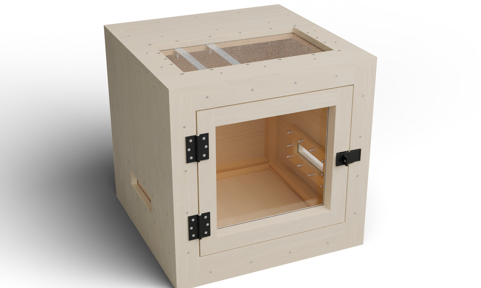
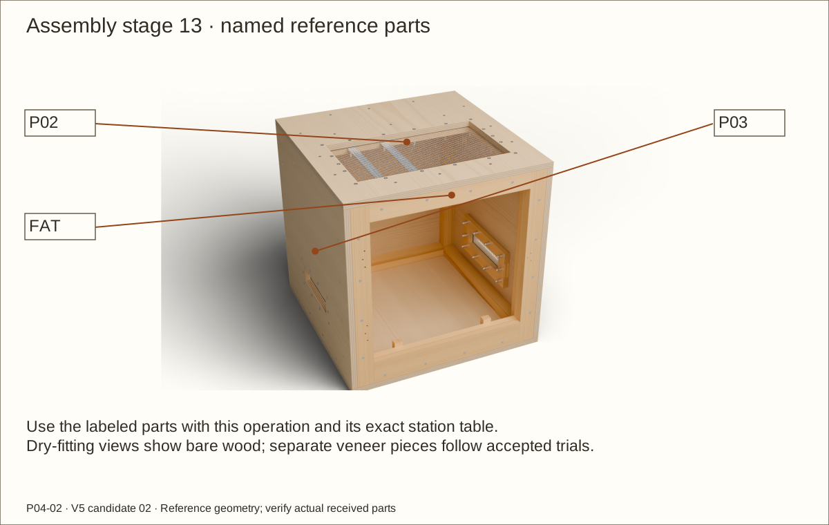
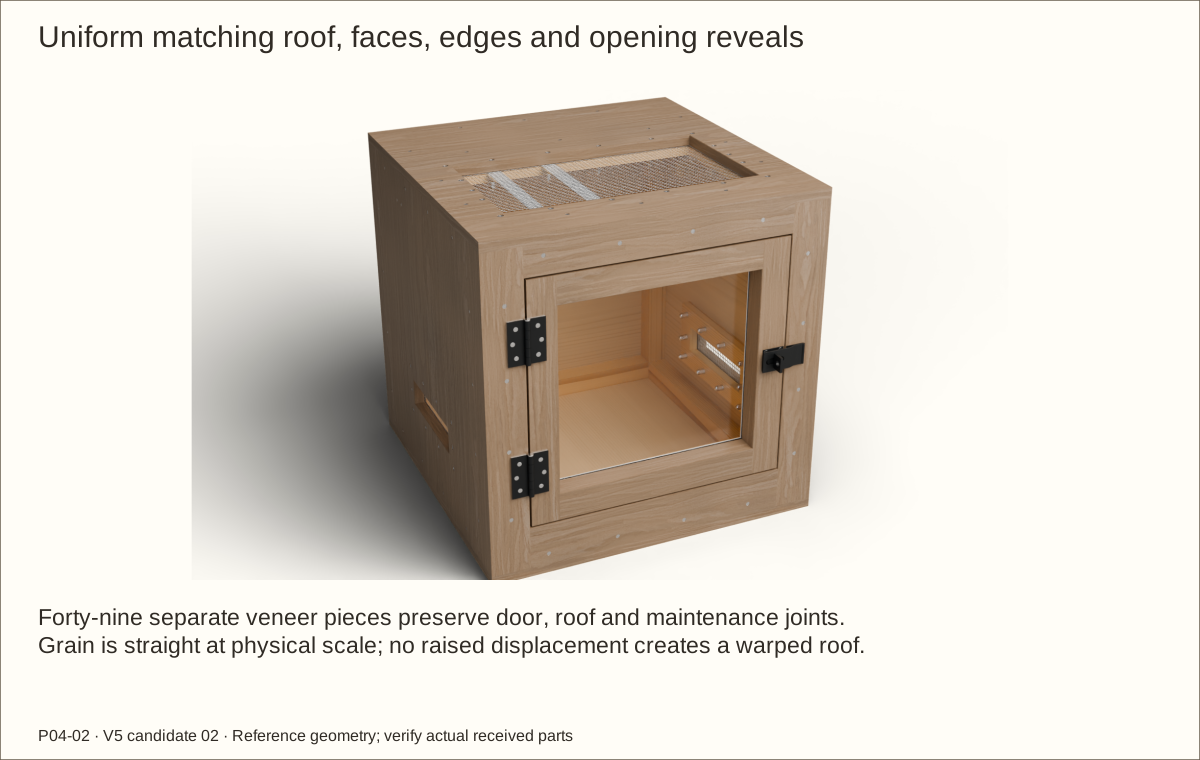
Full exterior veneer: the roof, faces, edges and reveals are included in this guide’s coordinated veneer schedule and geometry. Supplier balance, bond and actual-stack acceptance remain required. Natural grain and color vary.
About these previews
Rendered from this enclosure’s actual reference geometry. Veneer layers preserve service seams and bare hardware seats. The 3D viewer shows maple; these choices change the main picture. Texture scans by Jenelle van Heerden via Poly Haven, CC0 illustrate appearance and are not delivered veneer samples.
One hinged acrylic door with a swivel-staple hasp, a removable screened roof and low screened inlets. Follow 51 pictured operations with checks before continuing.
Before construction: supplier acceptance of the hinge spacers, received hardware and finish trials, prototype construction, physical testing and qualified review remain open. Publication approved; construction holds remain.
Receive and trial actual materials before dependent final cuts. This design retains P04-02’s single-door construction and its own hardware. Changed plywood, veneer, acrylic or hardware requires the corresponding fit checks.
Measurement
Reference
Bare exterior
24 × 24 × 24 in (609.6 × 609.6 × 609.6 mm)
Reference covered wooden body
24.061 in (611.15 mm) × 24.061 in (611.15 mm) × 24.061 in (611.15 mm)
Maximum covered wooden body
24.092 in (611.94 mm) × 24.092 in (611.94 mm) × 24.092 in (611.94 mm)
Door, bare wood
18 1/4 in (463.55 mm) × 17 7/32 in (437.36 mm)
Bare door gaps
Hinge/top/bottom 3/16 in (4.76 mm); latch 5/32 in (3.97 mm)
Minimum finished closed reveal
1/16 in (1.59 mm); receiving and animal-specific containment review required
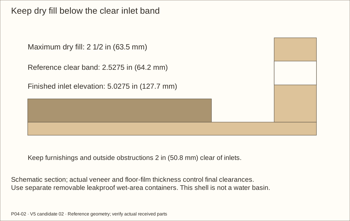
2 1/2 in (63.5 mm); reference 2.5275 in (64.2 mm) clear below finished inlets
Hinge service
22 in (558.8 mm) clear in front and 4 in (101.6 mm) above upper pin
Veneer stack
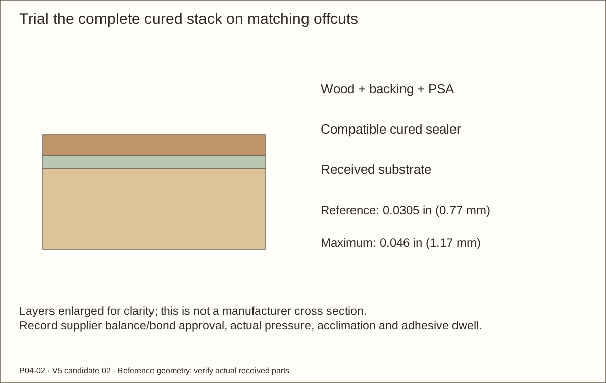
Reference 0.0305 in (0.77 mm); maximum 0.046 in (1.17 mm)
Measurement language: in means inches; mm means millimetres. Width × depth × height describes the outside body. Exact decimals are kept for mating parts. X starts at outside LEFT, Y at outside FRONT and Z at FLOOR UNDERSIDE unless a drawing names a local edge. Hardware projects beyond the wooden envelope.
Tools, terms and workholding
Use a flat supporting bench, helpers, clamps, straight cauls, tape, square, caliper, marking knife, measuring strips/dividers and stopped drill setups. Cutting needs supported saw and guided router/jigsaw arrangements, a chisel, block plane and sliding bevel. Plane wide stock before ripping narrow strips.
Prepare actual-root-matched wood pilots, clearance bits and matching countersink. Metal needs a vise, appropriate saw/bits, backing block and files. Mesh needs snips and edge protection. Acrylic needs a suitable sharp blade, full support and compatible edge finishing. Veneer needs a sharp knife, straightedge, cutting board and manufacturer-approved scraper.
Wear eye/hearing protection, control wood dust and ventilate finishes. Protect hands from cut mesh and metal; keep gloves, loose clothing and fingers away from rotating machinery. Clamp work and waste; never hold a short part under a drill.
Term
Plain meaning
Cleat / ledger
Wood strip receiving screws / strip supporting an upper panel
Stile / rail
Vertical / horizontal member of a frame
Lamination / caul
Layers glued together / straight board spreading clamp pressure
Pilot / clearance hole
Thread-guiding hole in receiver / free passage through first member
Countersink / arris
Conical flat-head seat / meeting edge of two faces
Named measuring surface / width removed by a saw cut
PSA / RH / BOM
Pressure-sensitive adhesive / relative humidity / bill of materials
Actual-stock fitting worksheet
Record dimensions before dependent final cuts. Reference drawings use 45/64 in (17.86 mm) plywood; t below means the measured uniform plywood thickness. Use actual clamped receivers and offcut gauges. Mixed thickness, warped stock or a failed fit requires a coordinated revision.
Part / fit
Reference or fitting rule
Actual / checked
Plywood t
45/64 in reference; fitting range 11/16–23/32 in (17.46–18.26 mm)
________
P03/P04 side height; P05 back width/height
24 in (609.6 mm) minus twice t
________
C1–C4 posts
Fit side height between floor and roof
________
C5–C8 side supports
24 in (609.6 mm) minus t minus 4 1/2 in (114.3 mm)
________
C9–C13 cross members
24 in (609.6 mm) minus twice t minus 3 in (76.2 mm)
________
Front frame
Fit between actual sides; cross seams and preserve opening
________
Door perimeter
Actual opening minus 11/32 in (8.73 mm) in width and 3/8 in (9.53 mm) in height
________
Glazing / screens / roof
Measure actual cured pocket, crossing thickness and capture clearance
________
Transfer the real frame and support centerlines before drilling. The appendix coordinates describe the reference assembly and do not automatically move for different stock. Recheck door/window datums, hasp plate support, glazing fit, veneer gaps and every hardware path before cutting or drilling dependent parts. Record the revised cuts and station marks; never force a part to match the reference table.
Tools / setup: Tape, square, pencil, clamps and the tools named in the operation
Before you begin: This unbuilt dry indoor shell has no species, structural, thermal or containment certification.
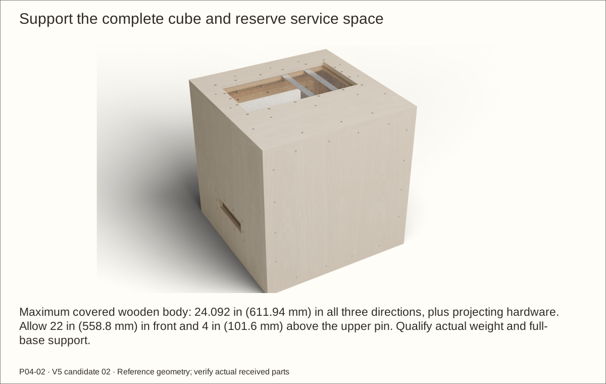
Plan full support and service space
Provide a flat, level support under the whole base. The bare body is 24 in (609.6 mm) wide × 24 in (609.6 mm) deep × 24 in (609.6 mm) high; the maximum veneered wood envelope is 24.092 in (611.94 mm) in each direction. Hardware projects farther.
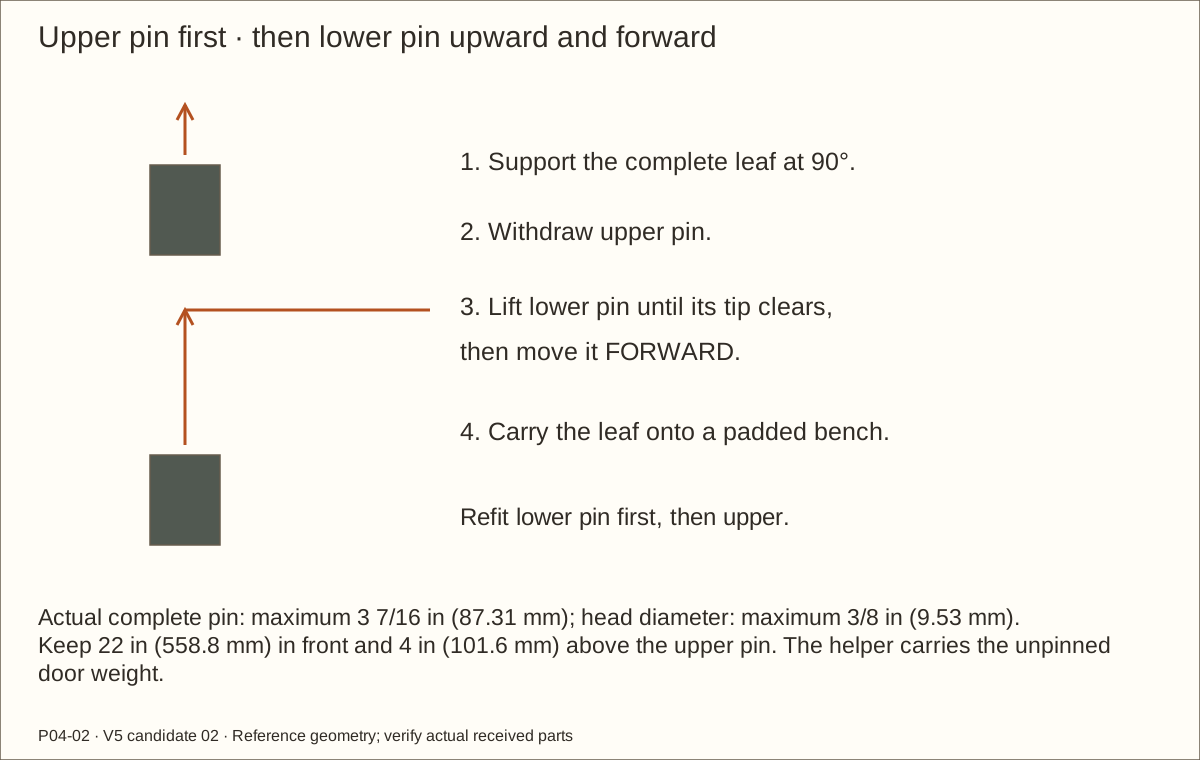
Check the transport route, helpers and working space. Reserve 22 in (558.8 mm) in front for the supported leaf, 4 in (101.6 mm) above the upper pin and clear lifting room above the entire roof. Keep the side bolt sets accessible.
Record the complete enclosure, substrate, furnishing and equipment weights. Have the support and floor checked for that actual load; no stand, stacking capacity or tested load rating is supplied.
Check before continuing: The whole base is supported and the empty cube can be transported and serviced.
Tools / setup: Tape, square, pencil, clamps and the tools named in the operation
Before you begin: Primary replacement hardware dimensions are recorded. Actual stack, quarter-inch mesh gauge and supplier/qualified acceptance remain open; product identity does not approve the assembly.
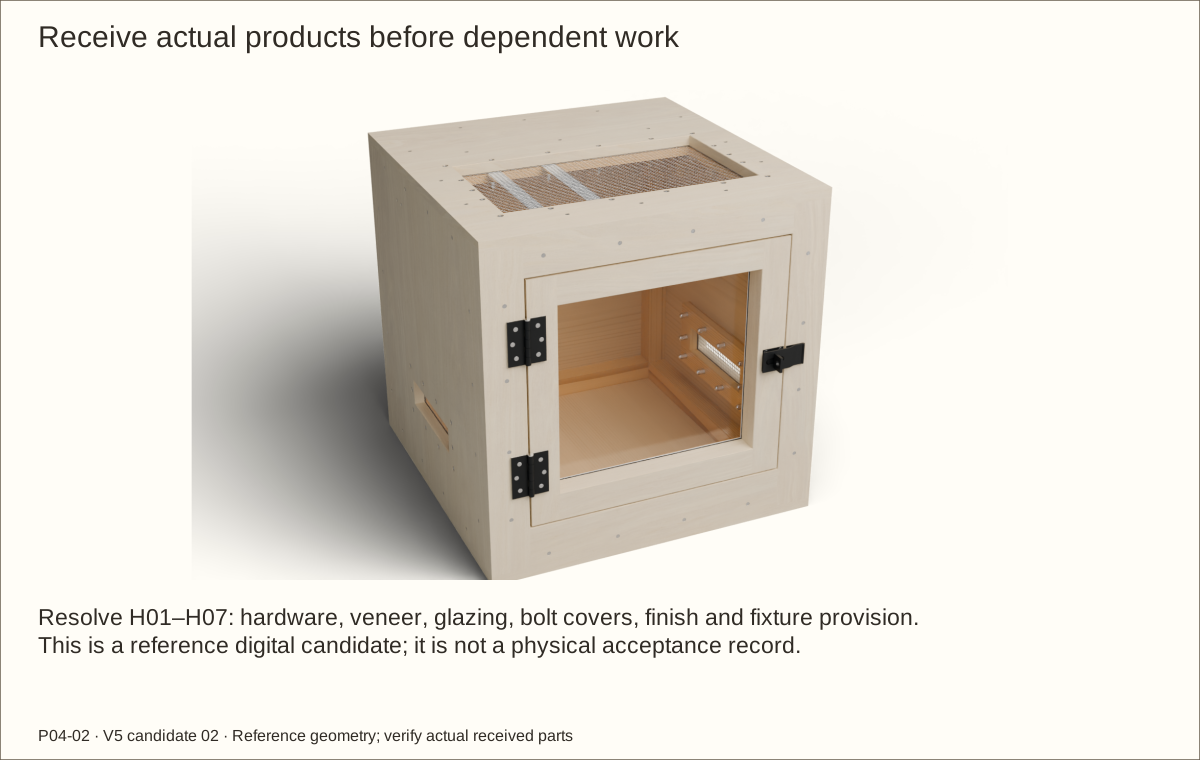
Resolve the seven receiving holds
Read H01–H07 before buying dependent materials. Confirm the proposed full-leaf hinge spacers, actual hasp support, mesh thickness, covered bolt tails and glazing-cushion compatibility.
Choose ONE maple, white-oak or walnut veneer system. Confirm its pressure-sensitive adhesive (PSA), backing, substrate/sealer, balance, indoor conditions, acclimation, application pressure and dwell with the supplier.
Record the answers and actual trials. The complete cured veneer stack must be no more than 0.046 in (1.17 mm). An added balancing layer or substituted hardware needs coordinated dimensional review.
Check before continuing: Required product and qualified-review answers are recorded before dependent work.
Parts: Plywood, pine, poplar, acrylic, gaskets, metal and hardware
Tools / setup: Tape, square, pencil, clamps and the tools named in the operation
Before you begin: Nominal lumber names are not measured finished dimensions.
Measure stock and identify every component
Match exact product models and quantities to the materials list. Keep unknown-length kit screws separate. Measure plywood at several edges; reference is 45/64 in (17.86 mm), with the fitting worksheet covering uniform 11/16 in (17.46 mm) through 23/32 in (18.26 mm) stock.
Verify 3/4 in (19.05 mm) pine, solid 1 1/2 in (38.1 mm) square pine, 3/8 in (9.53 mm) pine spacers, 1/4 in (6.35 mm) poplar caps and 0.22 in (5.59 mm) acrylic. Reject bowed, split, twisted or locally voided stock where it bears or receives a screw.
Save offcuts as thickness gauges and label their measured thickness. Fit dependent parts between their real receivers, then record the actual sizes beside the reference cut list.
Check before continuing: Stock dimensions, condition and product identities are recorded.
4. Trial pilots and head seats on matching offcuts
Parts: Actual #8 and #10 screws; matching wood and metal offcuts
Tools / setup: Drill, caliper, actual bits, countersink, depth stop, clamps and backing board
Before you begin: Clamp small pieces; never hold them by hand under the drill.
Trial pilots and head seats on matching offcuts
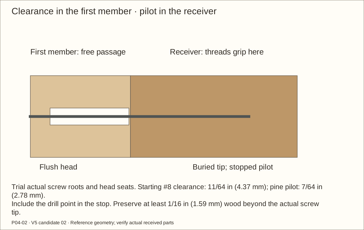
Clamp a representative stack over a backing board. A clearance hole passes the first member freely; a smaller pilot guides screw threads into the receiver. Start the #8 trial with 11/64 in (4.37 mm) clearance and a 7/64 in (2.78 mm) pilot, then match the received screw root.
Match the actual countersink angle, and stop with the head flush without crushing wood. Trial #10 hasp holes separately: reference 13/64 in (5.16 mm) clearance and 1/8 in (3.18 mm) pilot. Hardware countersinks must seat the actual heads.
Mark the intended tip and set a drill stop including the pointed end of the bit. Preserve at least 1/16 in (1.59 mm) wood beyond the screw tip. Inspect both sides after tightening; do not use a plywood edge as a threaded receiver.
Check before continuing: Joints close without splits, stripped threads, proud points or buried heads.
Before you begin: Support both sides of a cut; no store cutting service is assumed.
Cut and label the five plywood panels
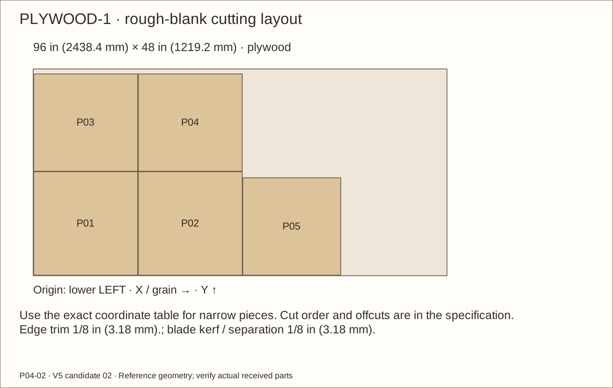
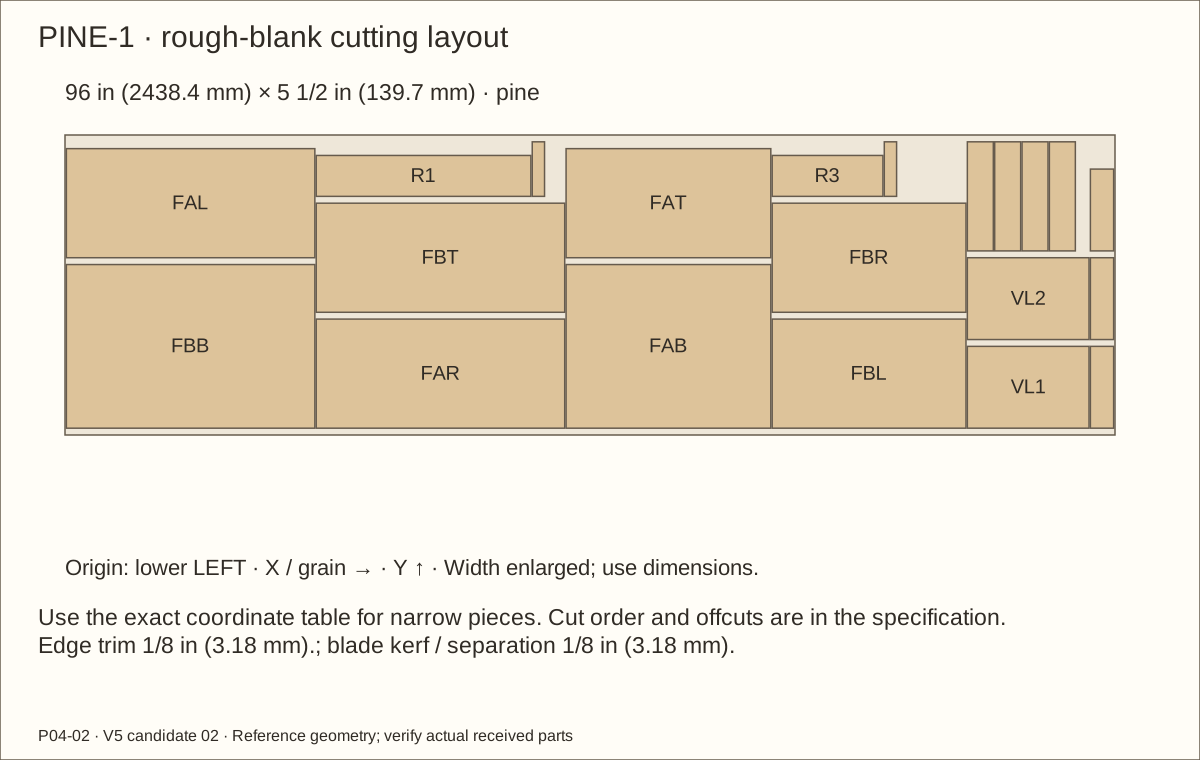
Support the sheet and waste on a sacrificial surface. Follow PLYWOOD-1, which fits a true 48 in (1219.2 mm) × 96 in (2438.4 mm) sheet with 1/8 in (3.18 mm) kerfs and edge trim. Finish floor P01 and roof P02 at 24 in (609.6 mm) square.
For the sides, subtract two actual plywood thicknesses from 24 in (609.6 mm). Reference side blanks are 24 in (609.6 mm) deep × 22 19/32 in (573.88 mm) high. Dry-clamp them on the floor and fit the back between: reference 22 19/32 in (573.88 mm) square.
Mark FRONT, LEFT/RIGHT, inside/outside and each part ID. Compare diagonals and mating edges before any opening is cut; retain the measuring offcuts.
Check before continuing: The dry-clamped bare shell has matching panels and the intended outside dimensions.
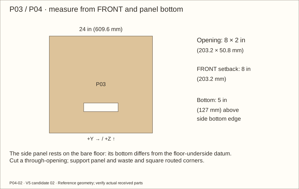
On each side mark an 8 in (203.2 mm) × 2 in (50.8 mm) through-opening. Its front edge is 8 in (203.2 mm) behind the panel FRONT; its bottom is 5 in (127 mm) above the panel bottom, which rests on the bare floor.
Clamp and back the panel. Drill a starter hole within the waste, cut with a supported jigsaw or guided router, and finish to the lines. Square routed corners without overcutting the wood.
Mirror the panel faces while preserving the same front/bottom datums. Veneer will cover the reveals; do not move the opening to compensate for a misplaced support.
Check before continuing: Both openings match their bare dimensions and remain clear of the supports.
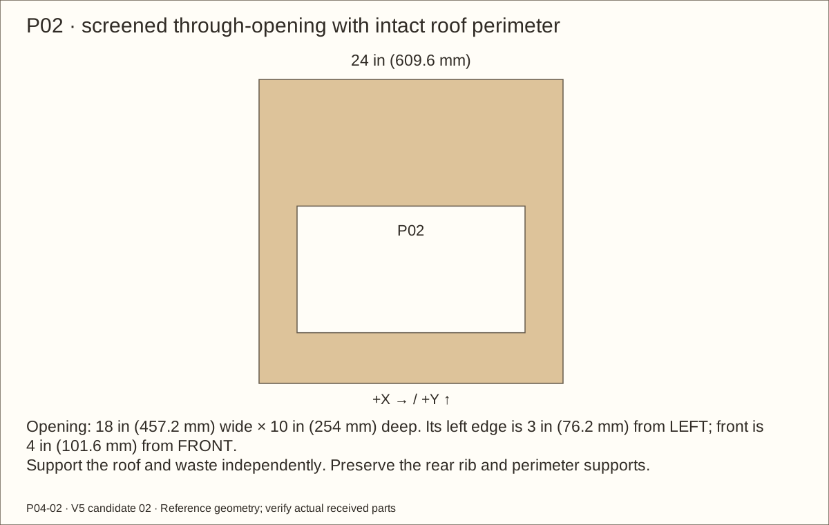
Mark one 18 in (457.2 mm) wide × 10 in (254 mm) deep opening. Its left edge is 3 in (76.2 mm) from LEFT and front edge 4 in (101.6 mm) from FRONT. Label the left fixture-support area.
Support the roof and waste independently. Cut inside the waste and finish to the lines with controlled passes; square the corners and remove splinters.
Preserve the surrounding roof, rear rib location and panel orientation. This is a real screened through-opening, not a shallow recess.
Check before continuing: The opening agrees with the roof drawing and leaves the specified perimeter.
Before you begin: Reject damaged or undersize stock; do not force long cleats into the shell.
Cut the thirteen solid supports
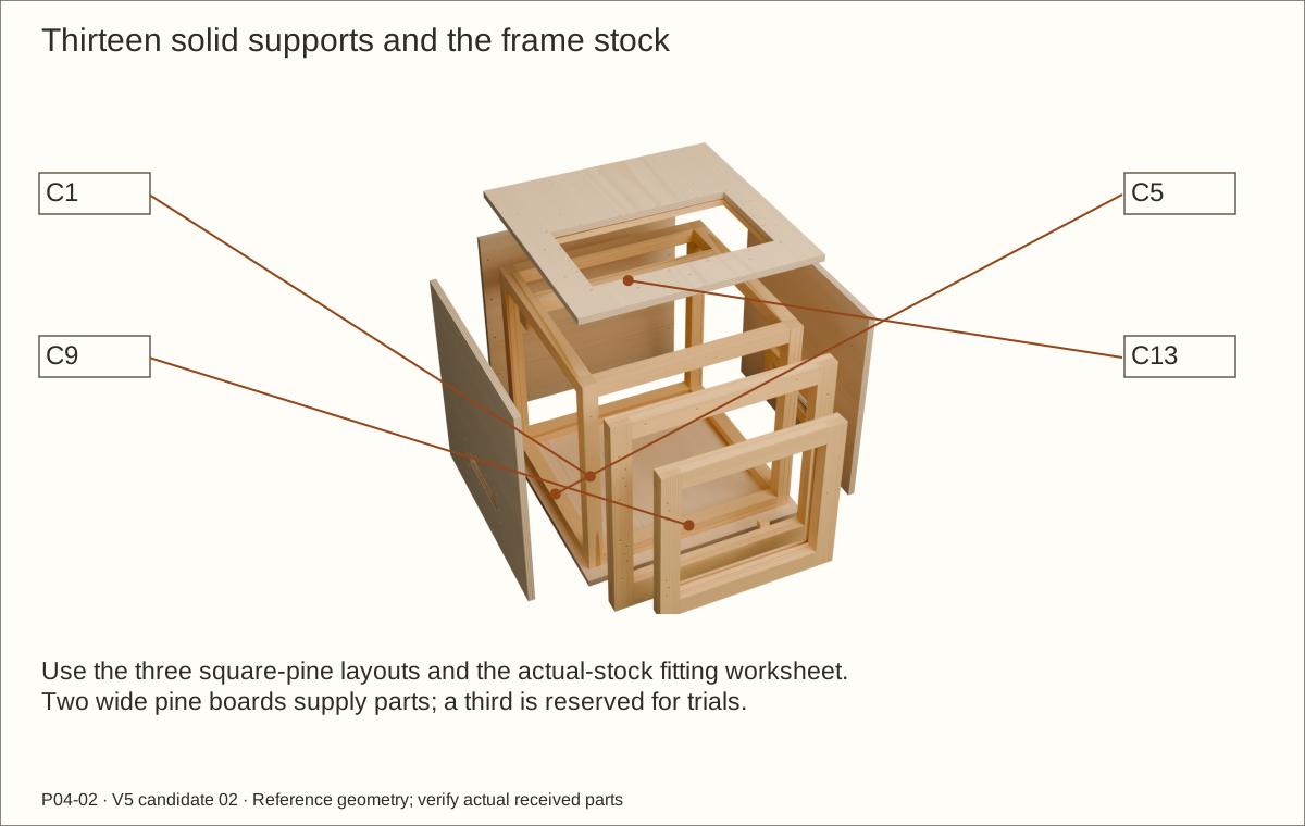
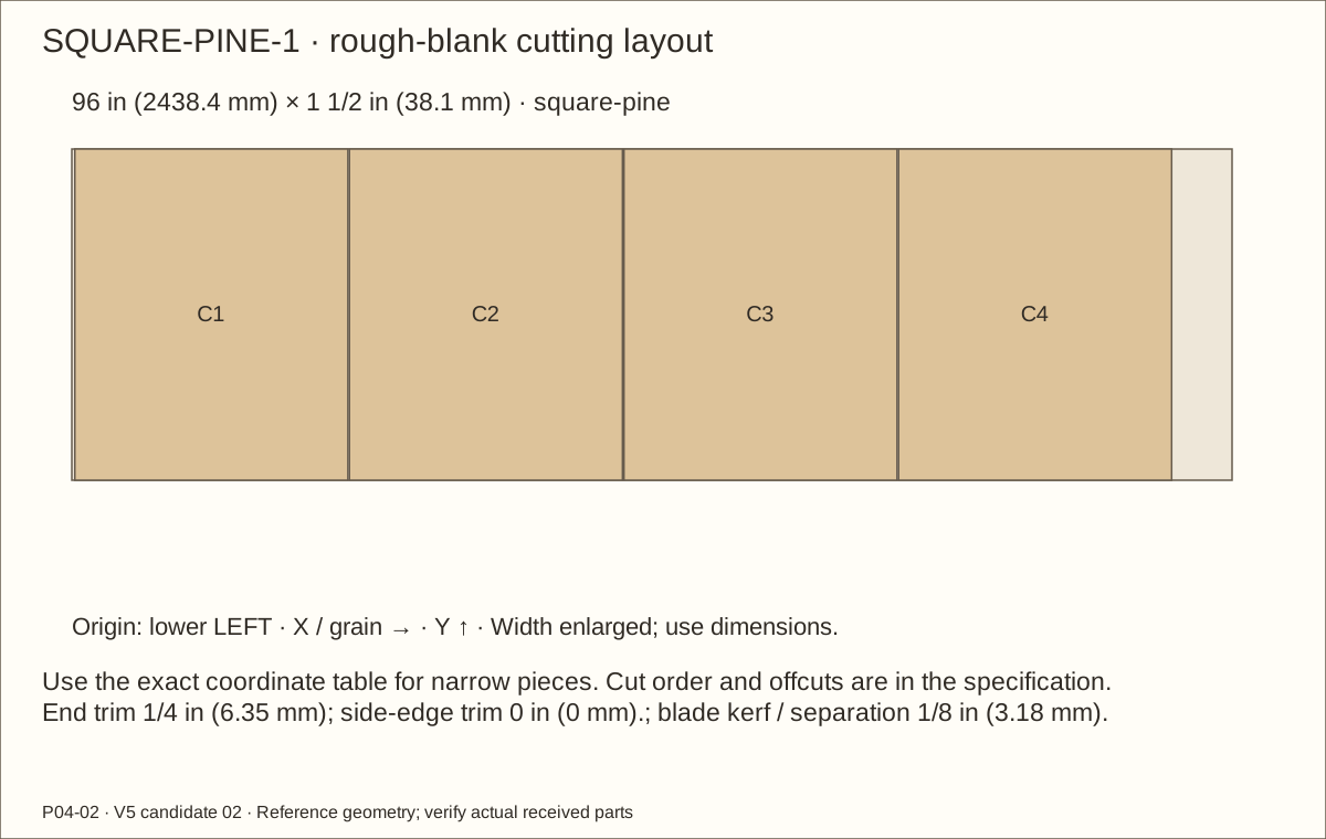
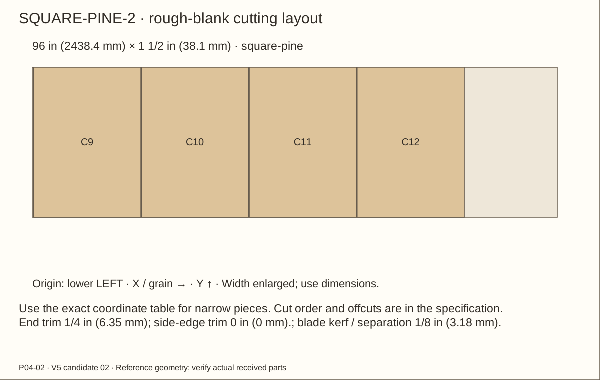
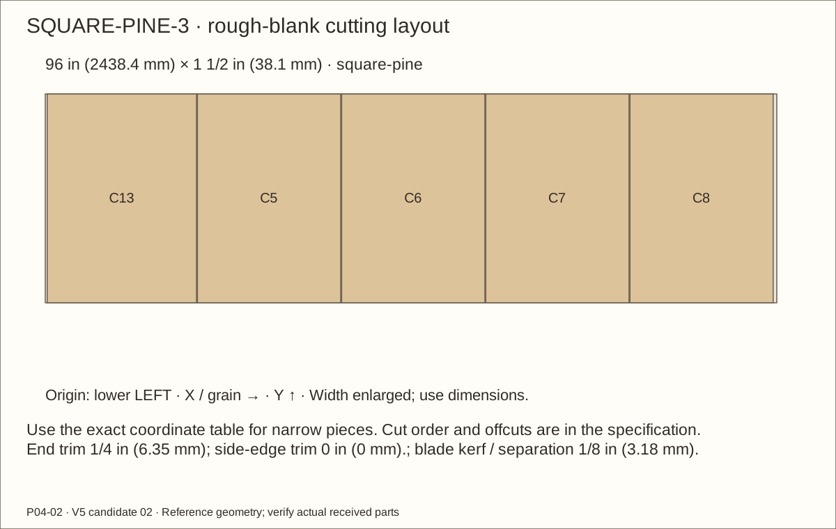
Use the three SQUARE-PINE layouts with measured fitting lengths. C1–C4 are reference 22 19/32 in (573.88 mm) posts; C5–C8 are 18 51/64 in (477.44 mm) side supports; C9–C13 are 19 19/32 in (497.68 mm) front/back/rib members.
Use solid clear 1 1/2 in (38.1 mm) × 1 1/2 in (38.1 mm) stock. The tight third-stick plan puts C13 with C5–C8 and includes 1/8 in (3.18 mm) kerfs; do not add arbitrary length allowances or reorder it into a longer group.
Transfer actual between-part distances with offcut gauges, check square ends, and label each member. Keep the square stock full section; these cleats are not laminated strips.
Check before continuing: Thirteen labeled solid members fit their actual receiving spaces.
Tools / setup: Tape, square, pencil, clamps and the tools named in the operation
Before you begin: The glue maker excludes structural/load-bearing use and continuous immersion.
Laminate the two rib bearing blocks
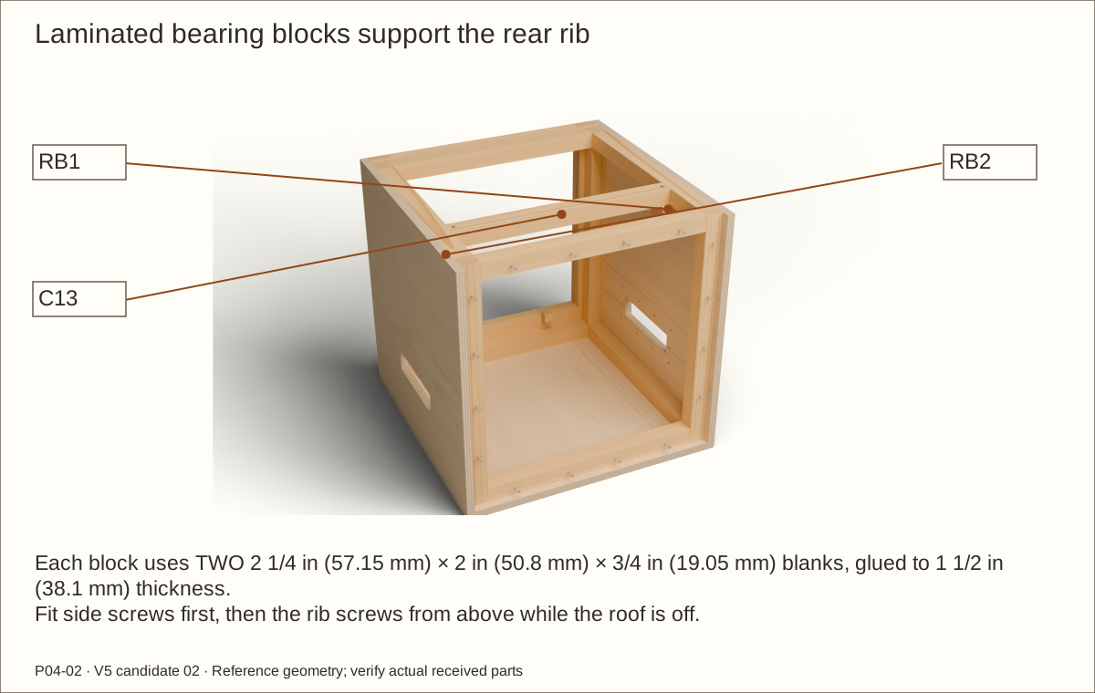
Cut four 2 1/4 in (57.15 mm) × 2 in (50.8 mm) × 3/4 in (19.05 mm) pine blanks. Pair them to form RB1 and RB2, each 1 1/2 in (38.1 mm) thick; dry-clamp all contacting faces on a flat bench.
Apply Titebond III to clean bare mating wood above 47°F (8.3°C). At 70°F (21°C) and 50% relative humidity, the maker gives 8–10 minutes open time and 20–25 minutes total assembly time.
Clamp uniformly with cauls, meaning straight boards that spread pressure. Remove squeeze-out and label the cured blocks; glue does not establish a structural rating.
Check before continuing: Both blocks are flat, fully contacting and at the intended size.
Required wait: Keep glue-ups clamped for this build’s 24-hour hold; do not stress or machine sooner. Extend for conditions and current maker instructions.
Tools / setup: Tape, square, pencil, clamps and the tools named in the operation
Lay out the crossed front-frame layers
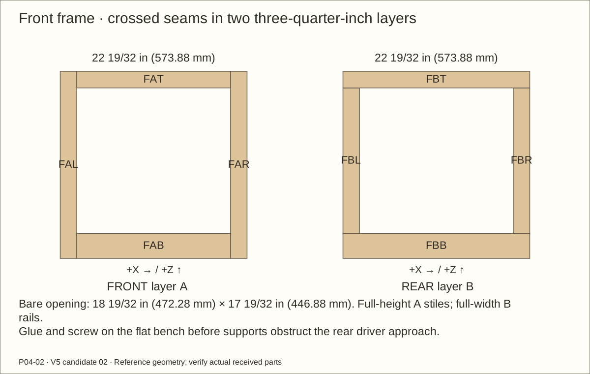
On a flat bench lay front layer A with full-height 2 in (50.8 mm) stiles, a 3 in (76.2 mm) bottom rail between them and a 2 in (50.8 mm) top rail between them.
Lay rear layer B with full-width top/bottom rails and its stiles between. Each layer bridges the other layer’s butt seams. The bare opening is reference 18 19/32 in (472.28 mm) wide × 17 19/32 in (446.88 mm) high.
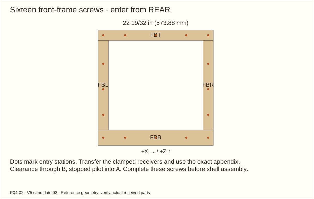
Dry-clamp, compare diagonals and mark the sixteen rear-entry lamination holes before the shell blocks access. Use the actual-stock worksheet for dependent rail and stile lengths.
Check before continuing: All seams are crossed, both layers lie flat and the opening is square.
Tools / setup: Tape, square, pencil, clamps and the tools named in the operation
Glue and screw the front frame on the bench
Apply glue and clamp under the same temperature/time conditions as the bearing blocks. Keep the frame flat while measuring both diagonals.
From REAR, mark the stile lines 1 in (25.4 mm) from each outside frame edge at heights 1 1/2 in (38.1 mm), 6 in (152.4 mm), 11 in (279.4 mm) and 16 in (406.4 mm) above the frame bottom, plus 1 in (25.4 mm) below the top. Mark the rail rows at 1 1/2 in (38.1 mm) above bottom and 1 in (25.4 mm) below top, at center and 6 in (152.4 mm) either side.
Use the station drawing for all sixteen holes. Clearance-drill the rear layer and blind-pilot the front layer; fit the scheduled screws flush on the bench. Later supports obstruct these driver paths.
Check before continuing: Sixteen flush screws reinforce the flat, square lamination.
Required wait: Do not stress, machine or install until the 24-hour glue hold is complete.
Tools / setup: Tape, square, pencil, clamps and the tools named in the operation
Before you begin: Do not use the original 1/8 in (3.18 mm) reveal dimensions for the full veneer option.
Fit the revised door perimeter
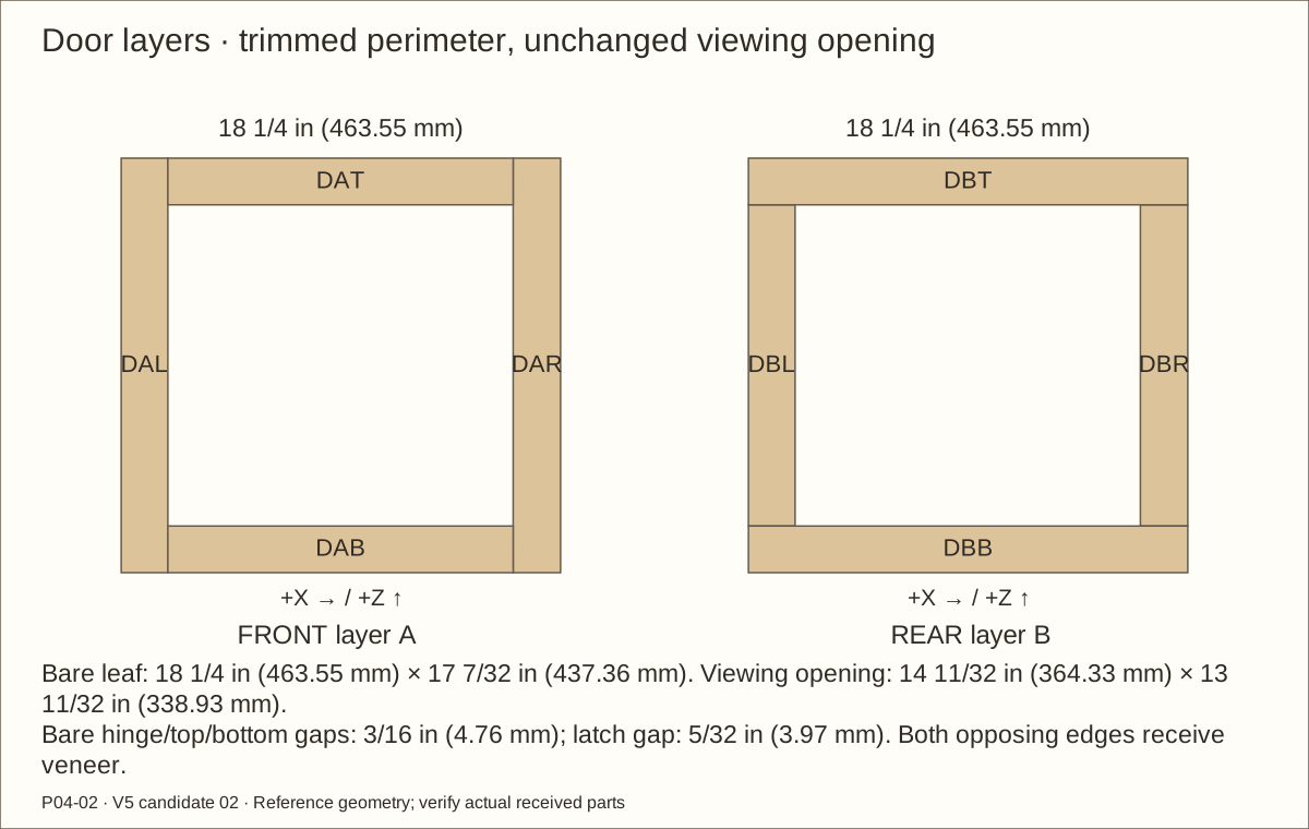
Fit the leaf to its own front opening with 3/16 in (4.76 mm) bare gaps at hinge, top and bottom and 5/32 in (3.97 mm) at the latch. Both opposing surfaces will receive veneer.
The revised bare leaf is 18 1/4 in (463.55 mm) wide × 17 7/32 in (437.36 mm) high. Retain the original 14 11/32 in (364.33 mm) × 13 11/32 in (338.93 mm) viewing opening and all glazing datums; only the outer perimeter is trimmed.
Layer A has full-height stiles, layer B full-width rails. Use each labeled cut and dry-lay the eight pieces so every butt seam is bridged.
Check before continuing: The leaf fits with the revised bare gauges and unchanged viewing opening.
13. Glue and screw the leaf before adding retainers
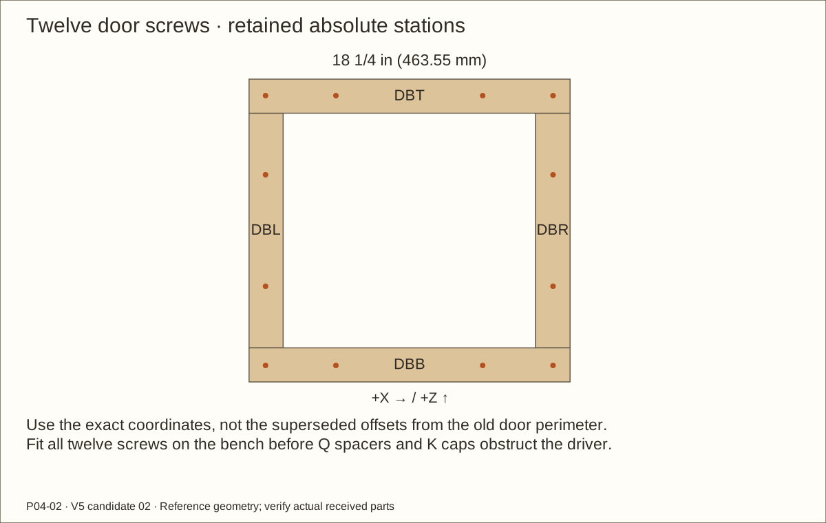
Parts: Door layers; twelve #8 × 1 1/4 in (31.75 mm) screws
Tools / setup: Tape, square, pencil, clamps and the tools named in the operation
Glue and screw the leaf before adding retainers
Glue the clean bare mating faces and clamp square on the bench under the established glue conditions. Check diagonals and flatness without using acrylic as a brace.
Use the appendix hole coordinates with the revised bare leaf: subtract 2 57/64 in (73.42 mm) from each X to mark from its LEFT edge, and 3 57/64 in (98.82 mm) from each Z to mark from its BOTTOM. Keep FRONT/REAR labels; do not reuse offsets from the old perimeter.
From REAR, clearance-drill layer B, blind-pilot layer A and fit twelve flush screws. Complete them before Q spacers and K caps block the driver approach.
Check before continuing: All twelve holes land in their intended receivers and the leaf remains flat.
Required wait: Keep the lamination unstressed for at least 24 hours before machining or hanging.
Before you begin: Do not shorten the latch edge further to cure a hardware error.
Plane the six-degree latch bevel
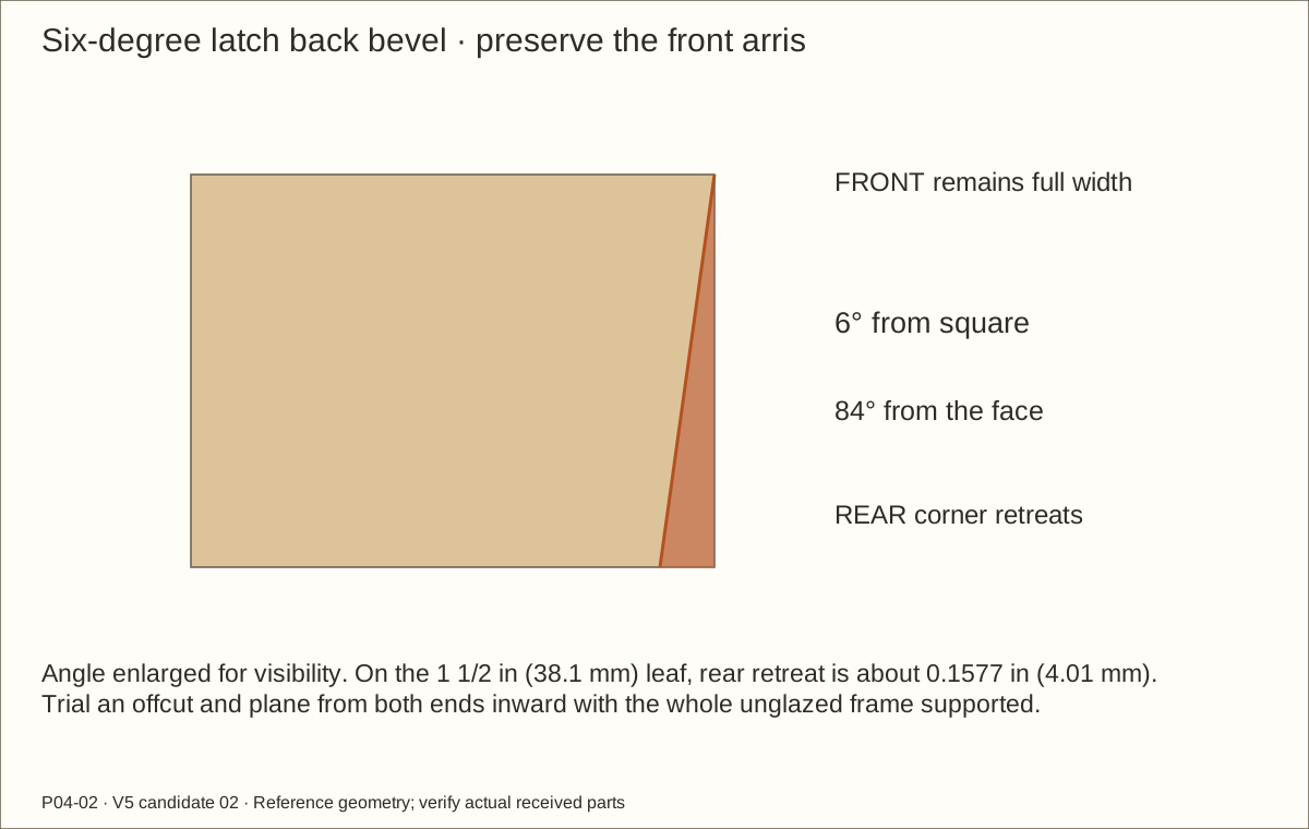
Mark FRONT and REAR. Preserve the new front latch arris, meaning the corner where the front and edge meet. Set a sliding bevel to 6° from square, or 84° from the face.
Trial a matching laminated offcut. On the 1 1/2 in (38.1 mm) leaf thickness, the rear edge retreats about 0.1577 in (4.01 mm); use the angle and straightedge to set the cut, not a rounded tape value.
Clamp the full leaf edge-up in padded jaws and plane light passes from the ends toward the middle. Keep the hinge edge square and recheck all bare gap gauges.
Check before continuing: The rear latch corner clears while the front arris and hasp-supporting wood remain intact.
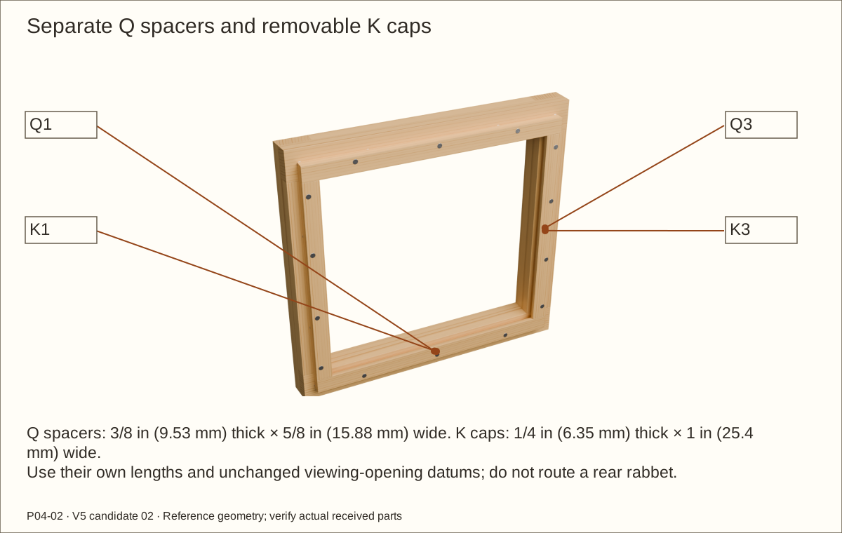
Use purchased 3/8 in (9.53 mm) pine for the Q spacers and 1/4 in (6.35 mm) poplar for the K caps. Rip safely supported long stock to 5/8 in (15.88 mm) and 1 in (25.4 mm) widths respectively, then crosscut the scheduled lengths.
Reference Q1/Q2 are 16 19/32 in (421.48 mm) long and Q3/Q4 are 14 11/32 in (364.33 mm). K1/K2 are 16 19/32 in (421.48 mm) and K3/K4 are 13 19/32 in (345.28 mm). Horizontal pieces span the pocket; vertical pieces fit between.
Keep the parts labeled and separate. This design uses a spacer-built pocket; do not route the other build’s rear rabbet into this leaf.
Check before continuing: Four spacers and four caps fit their own rectangles without twisting.
Tools / setup: Tape, square, pencil, clamps and the tools named in the operation
Before you begin: Protect future pane surfaces from chips and metal filings.
Dry-fit the glazing pocket and drill caps
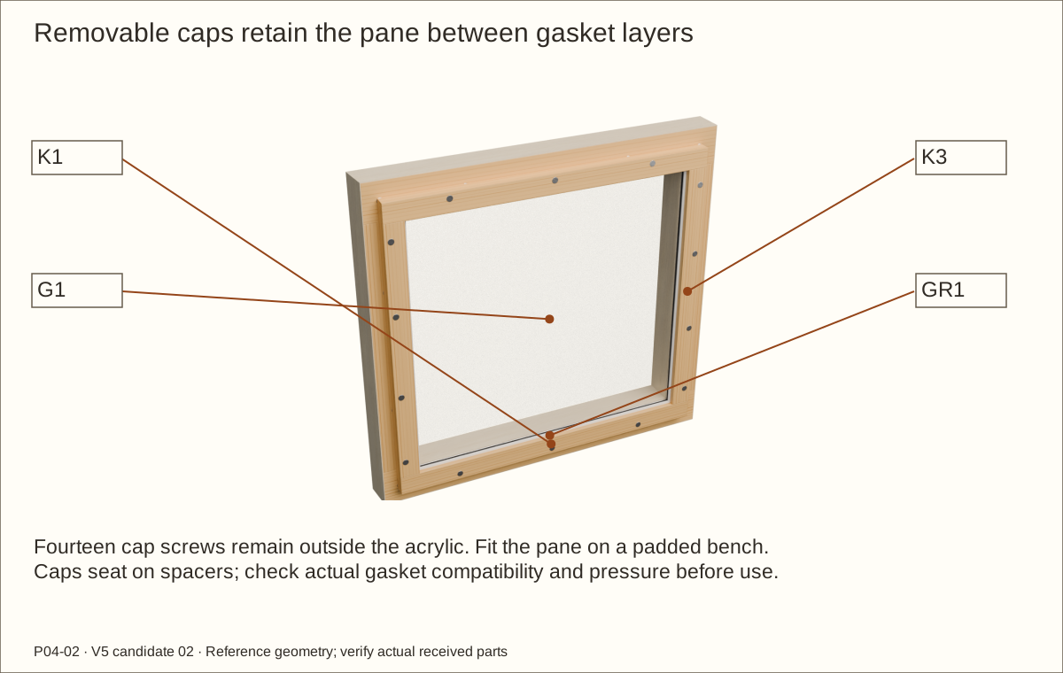
Place the leaf front down on a padded bench. Mark a rectangle 1 1/8 in (28.58 mm) outside each unchanged viewing-opening edge. Align the OUTER edges of both Q spacers and K caps to this rectangle; their different widths form the pocket and retaining overlap. Clamp flat.
With acrylic absent, mark and drill all fourteen stations: four per vertical cap and three per horizontal cap. Clearance passes through cap and spacer; the stopped pilot enters the leaf.
Dry-fit a representative acrylic/gasket stack. Leave caps and spacers removable; do not glue them or drill the acrylic. Final pressure and fit will be checked again after full cure.
Check before continuing: Caps seat without forcing a bowed leaf and all holes are outside the pane perimeter.
Tools / setup: Snips, file, caliper, gloves for wire handling and eye protection
Before you begin: Quarter-inch mesh is not insect-proof or universally animal-proof.
Cut and deburr the three mesh blanks
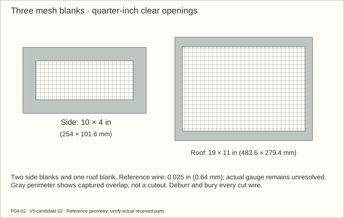
Cut two 10 in (254 mm) × 4 in (101.6 mm) side blanks and one 19 in (482.6 mm) × 11 in (279.4 mm) roof blank. Wear eye protection and suitable hand protection for sharp wire; file projections and inspect every weld.
The required clear aperture is 1/4 in (6.35 mm). The model assumes round 0.025 in (0.64 mm) wire at 0.275 in (6.99 mm) center pitch; the current listing does not establish gauge. Measure the actual welded crossings, which must not exceed 1/16 in (1.59 mm).
Check full overlap at each opening and flatten the captured perimeter without breaking welds. Every cut wire end must remain buried under its capture frame.
Check before continuing: All three screens fit, lie flat and have concealed sharp perimeters.
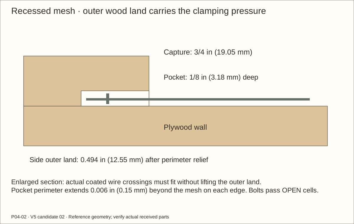
Dry-clamp each 11 in (279.4 mm) × 5 in (127 mm) capture frame from its two 11 in (279.4 mm) × 1 1/2 in (38.1 mm) rails and two 2 in (50.8 mm) × 1 1/2 in (38.1 mm) end pieces, all 3/4 in (19.05 mm) thick.
On the wall-facing side route the centered 10 in (254 mm) × 4 in (101.6 mm) mesh footprint plus 0.006 in (0.15 mm) relief at every perimeter edge, 1/8 in (3.18 mm) deep. Use a clamped carrier/template, never loose narrow strips.
Test the actual wire and cured coating. The continuous 0.494 in (12.55 mm) outer land must bear flat on the wall while the pocket contains the wire; square corners and remove sharp fibers.
Check before continuing: The outer wood land bears without being jacked off the wall by wire crossings.
Parts: Both inlet captures; twenty #10-24 bolt sets
Tools / setup: Actual mesh, clamps, transfer jig, drill, 7/32 in (5.56 mm) bit and backing board
Before you begin: Do not cut a mesh wire to make a hole fit. The receiving trial must preserve full wood bearing and tool access.
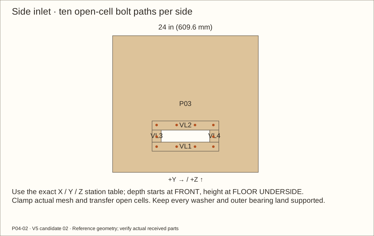
Transfer twenty side bolts through open cells
Clamp each mesh and capture with the land seated. Use the revised drawing’s stations, then adjust only by a documented received-mesh transfer that preserves support and clearances.
Reference depth stations from side FRONT are 7 1/4 in (184.15 mm), 10.55 in (267.97 mm), 13.575 in (344.81 mm) and 16.6 in (421.64 mm). Lower/upper rows are 4 61/64 in (125.81 mm) and 8.528125 in (216.61 mm) above FLOOR UNDERSIDE; the two end-column middle holes are at 6.603125 in (167.72 mm). The side panel bottom is one plywood thickness above that datum.
Drill ten 7/32 in (5.56 mm) through-holes per side through actual open cells. Clamp and back the stack; never cut a wire or weld to pass the bolt.
Check before continuing: Twenty bolts pass open cells with fully supported washers and concealed wire ends.
Parts: P03/P04 and later P02; bolts actual flat-head sample
Tools / setup: 82° countersink, stopped drill, actual bolts sample, 1/8 in (3.18 mm) hex key, caliper, clamps and backing
Before you begin: H05 offcut fit and H07 qualified bearing review remain required. A digital model cannot establish connection strength.
Countersink only the outside plywood faces
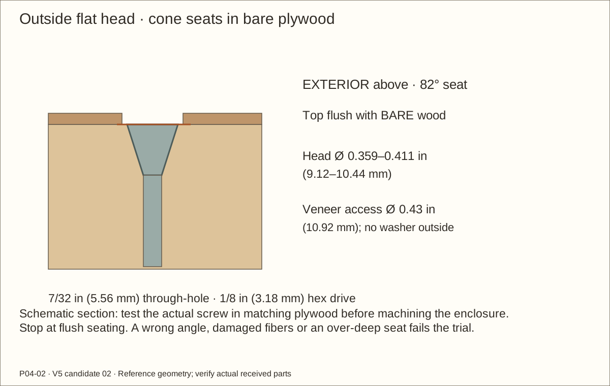
After transferring the 7/32 in (5.56 mm) through-holes, separate the stack. Clamp the plywood over sacrificial backing. Use an 82° countersink on the OUTSIDE face only; the cone supports the flat screw head.
Practice in matching offcuts first. Advance in small cuts, stop the drill and test the actual screw each time. Its top must be flush with bare wood. Published head diameter is 0.359 in (9.12 mm) – 0.411 in (10.44 mm); the maximum reference cone is about 0.127 in (3.23 mm) deep, leaving about 0.576 in (14.63 mm) of reference plywood below it.
Reject splitting, crushed fibers, voids, an oversized seat or a head below the face. Do not use a 90° countersink. Mark 0.43 in (10.92 mm) circular access in the later veneer so a 1/8 in (3.18 mm) hex key can reach each head; veneer must not carry clamping pressure.
Check before continuing: All outside heads seat flat and flush; the original through-hole and interior capture stay aligned.
Tools / setup: 1/8 in (3.18 mm) hex key, two slim 3/8 in (9.53 mm) wrenches, socket, caliper, vise, hacksaw and file
Before you begin: Stainless threads can seize. Work slowly by hand; stop for binding and follow supplier galling guidance. Any lubricant needs separate contact/finish approval. Never cut metal beside mesh or glazing.
Fit bolt lengths and blind covers
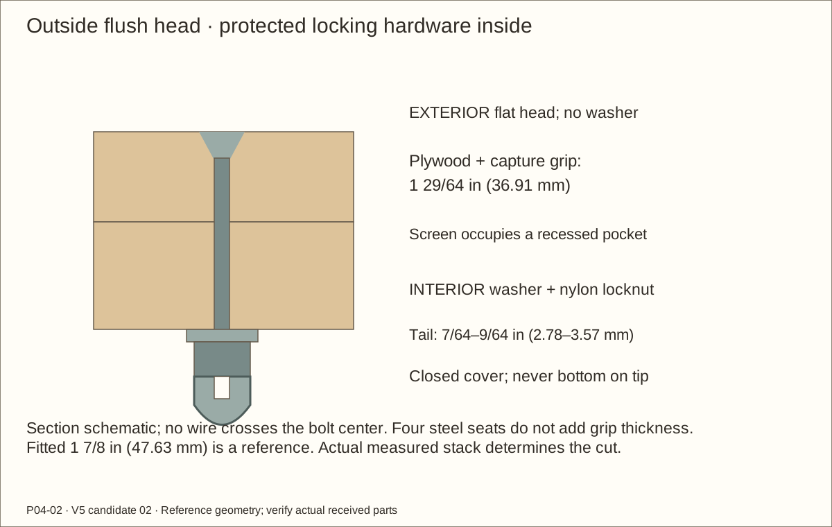
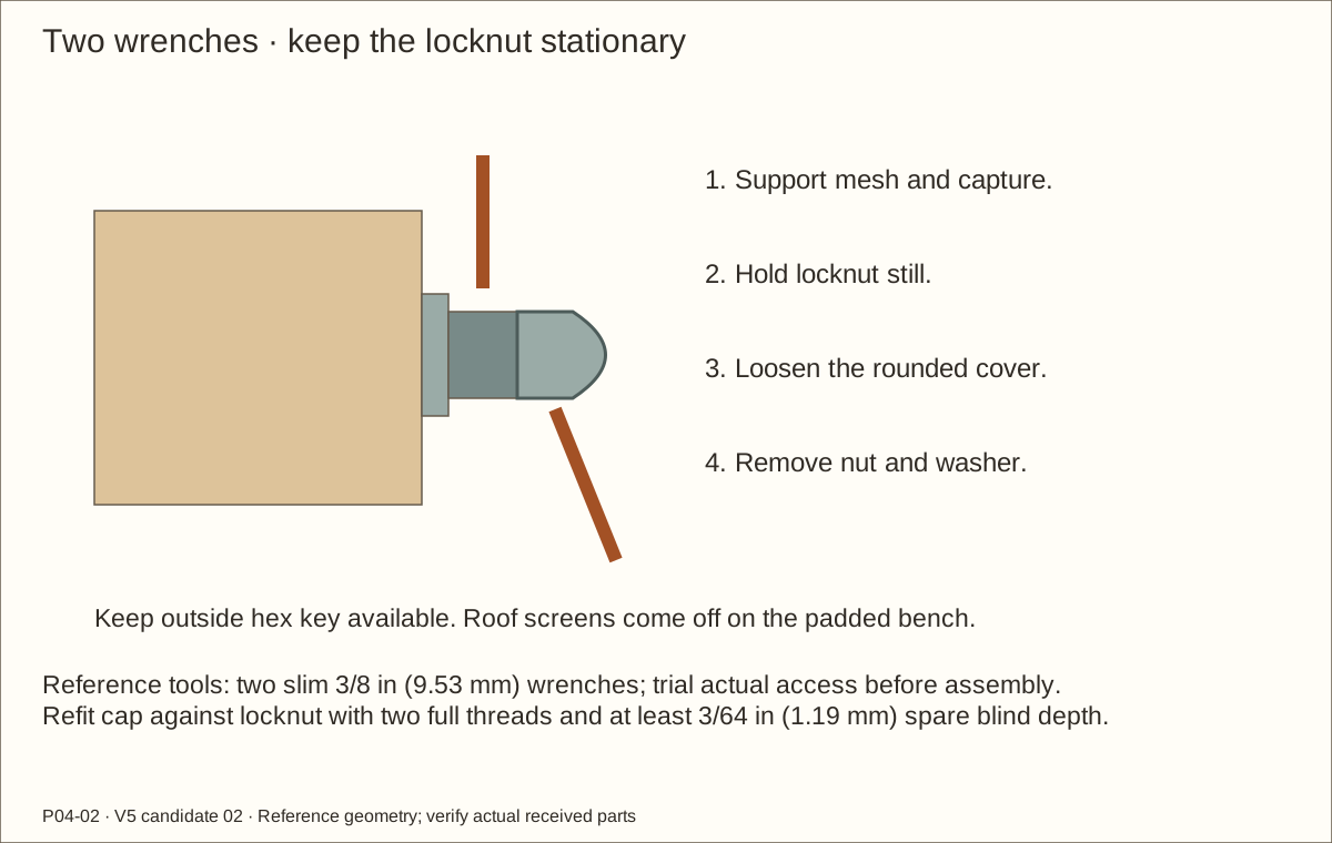
Insert each flat head from outside. Inside, place ONE washer against the capture and add the nylon locknut. Hold the head with a 1/8 in (3.18 mm) hex key and seat the nut slowly with a 3/8 in (9.53 mm) tool. Stop when lands touch; do not crush wood. A 5/8 in (15.88 mm)-outside-diameter-or-smaller socket and two slim wrenches must fit the actual trial.
Start with purchased 2 in (50.8 mm) screws, measured from the top of the head. Reference fitted length is 1 7/8 in (47.63 mm). Measure the actual plywood/capture grip, washer and nut; leave 7/64 in (2.78 mm) – 9/64 in (3.57 mm) beyond the nut. Remove the screw, clamp in a vise, cut and file with no more than 1/64 in (0.4 mm) chamfer. Keep at least two complete cap threads after the chamfer.
Refit the screw, washer and locknut. Thread on the closed cover by hand. Its 3/16 in (4.76 mm) blind depth must not bottom on the tip; leave at least 3/64 in (1.19 mm) spare depth. Hold the locknut stationary with one wrench while snugging the cover with another. The locknut retains the joint; the cap only covers the tail.
Check before continuing: Every head is flush outside; every interior tail is covered, positively engaged and accessible without crushing wood.
Tools / setup: Tape, square, pencil, clamps and the tools named in the operation
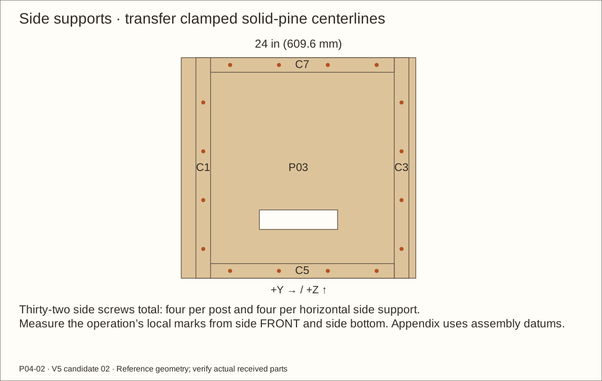
Attach the side supports on the bench
Lay each side inside-up. Front posts begin 1 1/2 in (38.1 mm) behind FRONT; rear posts meet the future back. Fit upper/lower side supports between posts, flush to the panel top/bottom.
Clamp and transfer each post centerline to the outside. Mark 3 in (76.2 mm), 8 in (203.2 mm), 13 in (330.2 mm) and 18 in (457.2 mm) above the side panel bottom, four screws per post.
For the horizontal supports, mark 5 in (127 mm), 10 in (254 mm), 15 in (381 mm) and 20 in (508 mm) behind FRONT, 3/4 in (19.05 mm) from the panel top or bottom. Clearance-drill plywood, blind-pilot solid pine and fit the thirty-two screws.
Check before continuing: Posts and supports bear flat without obstructing the inlet captures.
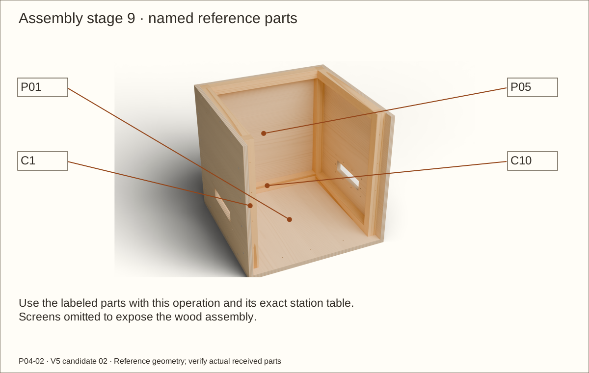
Parts: P01, side assemblies, P05, C10/C12; sixteen back screws
Tools / setup: Tape, square, pencil, clamps and the tools named in the operation
Before you begin: Do not leave the loose-bottom U-shaped shell unsupported.
Brace the shell and fasten the back
On full support, stand the sides on the floor and dry-fit the back between them. Use clamps, temporary braces and a helper; the floor has not yet been fastened.
Transfer rear-post centerlines to P05. Mark 5 in (127 mm), 10 in (254 mm), 15 in (381 mm) and 20 in (508 mm) above its bottom, 3/4 in (19.05 mm) from each back side edge. Fit eight #8 × 1 3/4 in (44.45 mm) screws after checking diagonals.
Fit C10/C12 between the posts, flush to the back panel bottom/top. Mark 4 in (101.6 mm) and 9 in (228.6 mm) from each back side edge, 3/4 in (19.05 mm) from top/bottom, and fit eight more screws.
Check before continuing: Both diagonals agree, the back is flush and the braced shell remains square.
Tools / setup: Tape, square, pencil, clamps and the tools named in the operation
Before you begin: Use the complete station drawing for transferred centerlines; do not drill into a plywood edge.
Fit the front and secure the floor
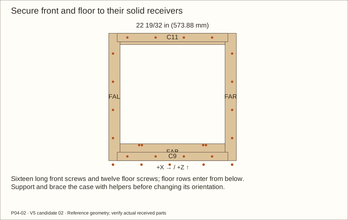
Fit the cured front frame between the sides with its front flush. Fit C9/C11 behind its lower/upper rails, between the front posts. Clamp and compare diagonals.
Use sixteen #8 × 2 1/2 in (63.5 mm) front screws: post rows 3/4 in (19.05 mm) from frame sides at 4 in (101.6 mm), 9 in (228.6 mm), 14 in (355.6 mm) and 19 in (482.6 mm) above frame bottom; rail rows 3/4 in (19.05 mm) from bottom/top at 4 in (101.6 mm), 9 in (228.6 mm), 14 in (355.6 mm) and 19 in (482.6 mm) from SHELL LEFT.
With helpers and the case braced, access the floor underside. Fit twelve #8 × 1 3/4 in (44.45 mm) screws: three per side-support centerline at 6 1/2 in (165.1 mm), 11 1/2 in (292.1 mm) and 18 1/2 in (469.9 mm) behind FRONT; front/back ledger rows at 6 1/2 in (165.1 mm), 11 1/2 in (292.1 mm) and 17 1/2 in (444.5 mm) from LEFT.
Check before continuing: Front, back and floor are square and every screw enters solid pine.
Parts: ST1/ST2; four #8 × 1 1/4 in (31.75 mm) screws
Tools / setup: Tape, square, pencil, clamps and the tools named in the operation
Install the lower door stops
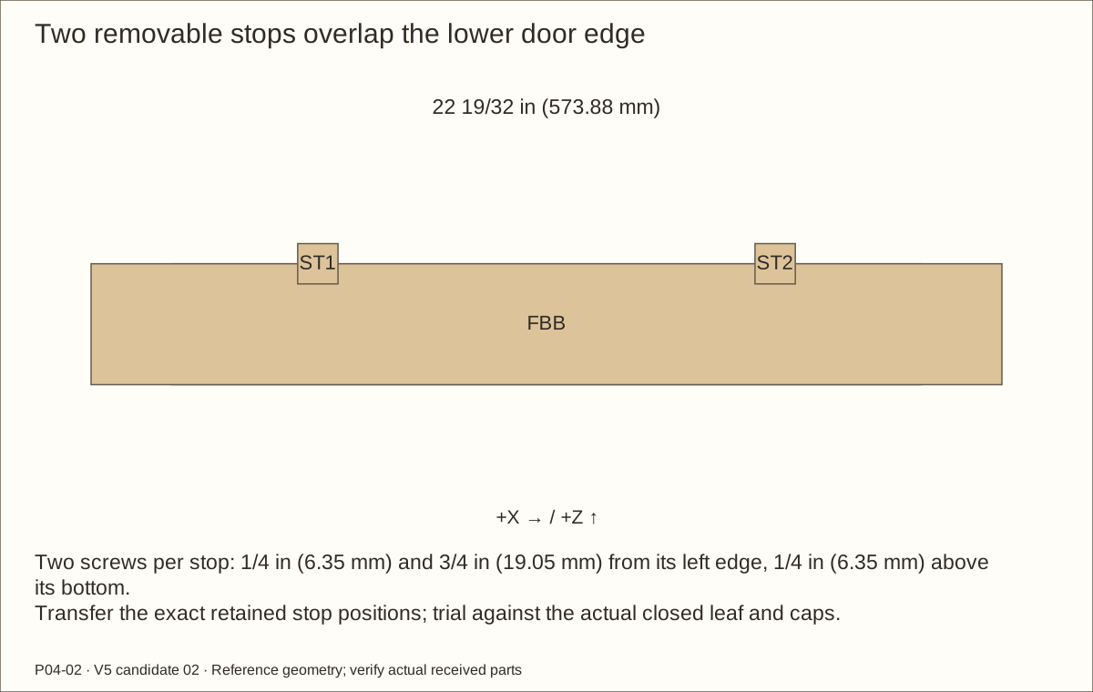
Place the 1 in (25.4 mm) square stops on the back of the lower front rail at their retained absolute locations. Their top edges overlap the closed leaf while staying clear of the glazing caps.
For each stop, mark holes 1/4 in (6.35 mm) and 3/4 in (19.05 mm) from its left edge, 1/4 in (6.35 mm) above its bottom. Clamp, clearance-drill the stop and blind-pilot the frame from the rear.
Fit four flush screws and trial the unglazed leaf against both stops. Neither block may twist the door or contact a cap.
Check before continuing: Both stops support the closed leaf evenly with glazing access clear.
Parts: RB1/RB2; four #8 × 1 3/4 in (44.45 mm) screws
Tools / setup: Tape, square, pencil, clamps and the tools named in the operation
Fasten the rib bearing blocks
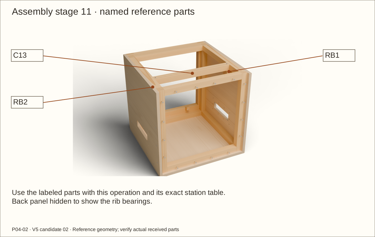
Clamp the cured blocks against the inside side panels, front at 15 3/4 in (400.05 mm) behind FRONT. The reference underside is 20 19/64 in (515.54 mm) above FLOOR UNDERSIDE; transfer the actual rib/support height instead of accumulating rounded measurements.
From each side mark two holes 1/2 in (12.7 mm) and 1 1/2 in (38.1 mm) behind the block front, 3/4 in (19.05 mm) above its bottom. Clearance-drill the plywood and blind-pilot the block.
Fit two screws per block, recheck level and keep the roof off for the next vertical screws.
Check before continuing: Blocks bear flat at equal heights and accept both rib ends.
Parts: C13, RB1/RB2; two #8 × 2 1/2 in (63.5 mm) screws
Tools / setup: Tape, square, pencil, clamps and the tools named in the operation
Seat and screw the rear roof rib
Place C13 across the blocks with its front 16 in (406.4 mm) behind FRONT. Each end bears 3/4 in (19.05 mm) along the span and 1 1/2 in (38.1 mm) front-to-back; the rib top aligns with the perimeter supports.
Mark one downward screw 3/8 in (9.53 mm) from each rib end and 3/4 in (19.05 mm) behind its front. Clamp and clearance-drill the rib, blind-pilot each block, and fit the two screws.
Use a straightedge across the roof supports and rib. Complete these vertical screws now; the roof would block the driver later.
Check before continuing: The rib is level, both bearing faces contact and no screw tip is exposed.
Tools / setup: Router, clamped carrier/template, chisel, depth gauge and actual steel/mesh
Before you begin: Only the two specified steel crossings interrupt the outer land.
Machine the roof screen and steel seats
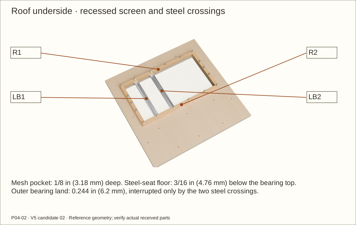
Dry-clamp the roof capture in its 19 1/2 in (495.3 mm) × 11 1/2 in (292.1 mm) rectangle. Its front-left is 2 1/4 in (57.15 mm) from roof LEFT and 3 1/4 in (82.55 mm) behind FRONT.
From the roof-facing side route the 19 in (482.6 mm) × 11 in (279.4 mm) mesh footprint plus 0.006 in (0.15 mm) relief per edge, 1/8 in (3.18 mm) deep. The outer land is 0.244 in (6.2 mm) wide. Work on a clamped carrier and square the corners.
Cut the two support-bar crossings in R1/R2 to the machining drawing. Relative to the new top bearing face, the steel-seat floor is 3/16 in (4.76 mm) down; the 1/8 in (3.18 mm) steel top meets the underside of the nominal mesh. Trial the actual coated stack.
Check before continuing: Roof lands bear flat and the steel/mesh stack fits without lifting the roof.
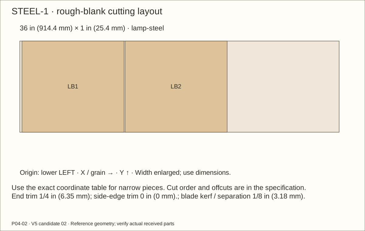
Parts: LB1/LB2; one 1 in (25.4 mm) × 1/8 in (3.18 mm) × 36 in (914.4 mm) steel bar
Tools / setup: Vise, hacksaw, file, drill, 1/4 in (6.35 mm) bit and backing board
Cut and drill the two steel strips
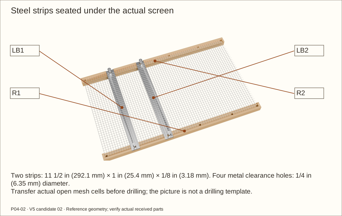
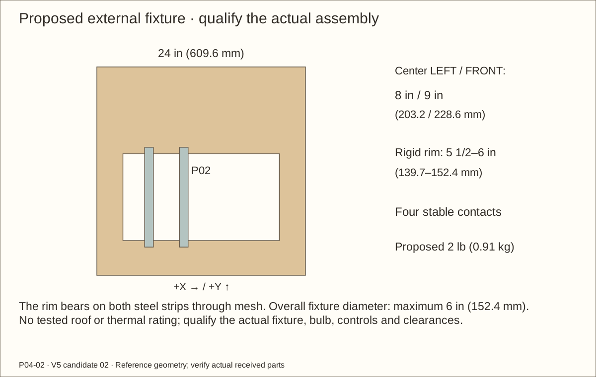
Clamp the bar and waste, cut two 11 1/2 in (292.1 mm) lengths, and file edges and corners smooth. Place the strips at X 5 1/2 in (139.7 mm) and 9 1/2 in (241.3 mm) from LEFT, running from Y 3 1/4 in (82.55 mm) to 14 3/4 in (374.65 mm) behind FRONT.
Transfer the four revised mesh-cell centers through the actual clamped stack. Reference X coordinates are 5.975 in (151.77 mm) and 10.1 in (256.54 mm), with Y 3.65 in (92.71 mm) and 14 3/8 in (365.13 mm); do not reuse the superseded exact strip-center holes.
Remove each strip, clamp it over backing and drill 1/4 in (6.35 mm) clearance at the transferred points, then deburr both faces. Refit the strip fully in its seats.
Check before continuing: Both strips sit flat and all four holes preserve supported metal around the bolt.
Tools / setup: Tape, square, pencil, clamps and the tools named in the operation
Before you begin: The screen and 2-pound fixture provision remain physically untested.
Bolt the roof screen on the bench
With the roof supported underside-up, position the mesh, seated steel and capture. Keep the front/left labels visible and all cut wire buried.
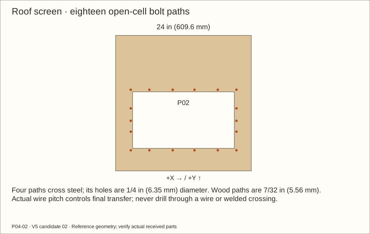
Use the revised roof station drawing to transfer eighteen 7/32 in (5.56 mm) wood paths through actual open mesh cells. Four paths also use the steel clearance holes. Check every washer seat and the uninterrupted lands.
Separate the roof and countersink its OUTSIDE top face at 82° as in the side trial. Fit eighteen sets: flat head above, one washer/locknut/closed cover below. Four pass recessed steel without added grip thickness. Fit and shorten removed screws by the measured-tail rule; assemble the roof screens on the padded bench before installing the roof.
Check before continuing: The complete assembly is flat, all eighteen bolts engage and caps cover smooth tails.
Tools / setup: Tape, square, pencil, clamps and the tools named in the operation
Trial the removable roof
With help, lower the roof onto the square shell and rib. The internal capture must clear the side supports by at least 1/64 in (0.4 mm) each side after coating; do not force or hammer it down.
Transfer support centerlines. Side rows use depth marks 6 1/2 in (165.1 mm), 11 1/2 in (292.1 mm) and 18 1/2 in (469.9 mm); front/back rows use width marks 6 1/2 in (165.1 mm), 11 1/2 in (292.1 mm) and 17 1/2 in (444.5 mm). The rib row is 16 3/4 in (425.45 mm) behind FRONT at width marks 5 in (127 mm), 12 in (304.8 mm) and 19 in (482.6 mm).
Clearance-drill the roof and blind-pilot the receivers, then fit fifteen flush screws. Keep the roof removable and mark its matched holes.
Check before continuing: The roof seats on all supports and the bare cube measures 24 in (609.6 mm) in each direction.
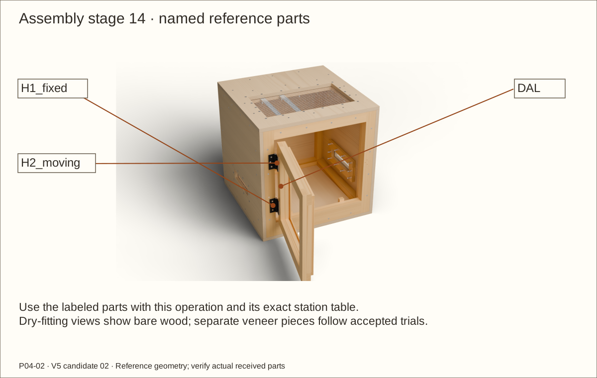
Parts: SP-H1-fixed/moving, SP-H2-fixed/moving; aluminium bar
Tools / setup: Vise, hacksaw, file, caliper, drill and 11/64 in (4.37 mm) bit
Before you begin: This custom mounting method has no supplier approval or tested capacity yet.
Make the four proposed hinge spacers
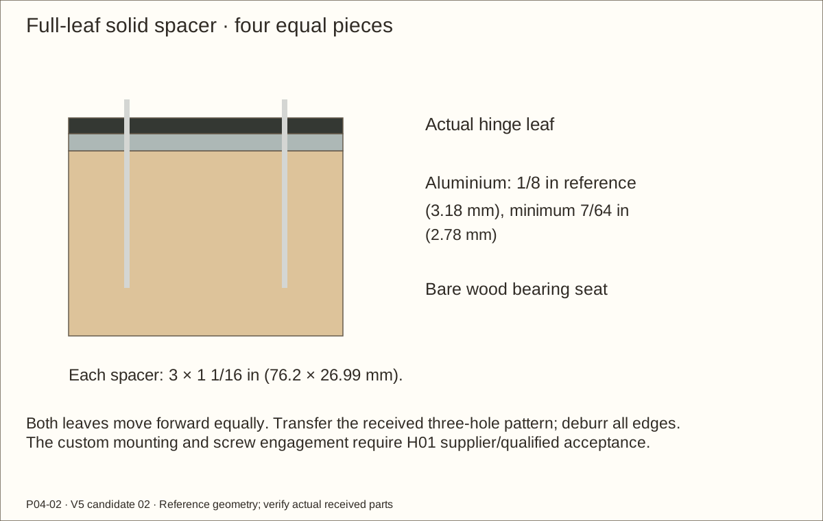
After H01 mounting acceptance, cut four 3 in (76.2 mm) × 1 1/16 in (26.99 mm) × 1/8 in (3.18 mm) full-leaf spacers. Clamp the bar and waste, file smooth and preserve flat bearing faces.
Match the actual hinge leaf footprint and equal spacer thicknesses, minimum 7/64 in (2.78 mm). Keep wood and metal bearing seats free of veneer, adhesive and compressible pads.
Clamp the actual leaf to each labeled spacer, transfer three holes and drill 11/64 in (4.37 mm) clearance through aluminium over backing. Deburr and trial the screw heads in the hinge.
Check before continuing: Each entire leaf and its holes are supported on an equal solid spacer.
33. Transfer the hinge holes with the leaf supported
Parts: Two 1798A21 hinges; twelve #8 × 1 1/4 in (31.75 mm) screws
Tools / setup: Tape, square, pencil, clamps and the tools named in the operation
Before you begin: Keep the heavy leaf supported throughout fitting; nominal screw engagement is not a strength approval.
Transfer the hinge holes with the leaf supported
Support the unglazed leaf in the revised bare gaps. Retain the two absolute hinge centers at Z 7 53/64 in (198.83 mm) and 17 11/64 in (436.17 mm) above FLOOR UNDERSIDE, with pivot X 2 49/64 in (70.25 mm) from LEFT.
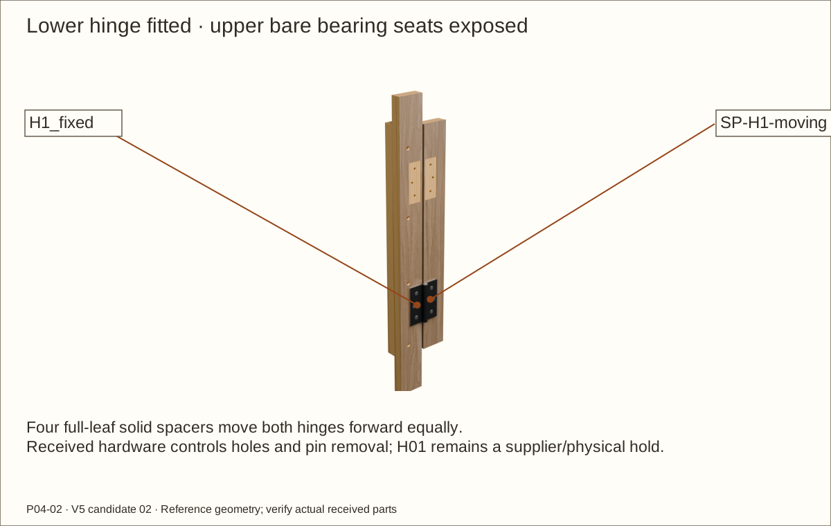
With matched spacers behind fixed and moving leaves, clamp the actual hinge and transfer its three holes per leaf. Its nominal pivot lies 5/16 in (7.94 mm) in front of the bare front plane.
Use the actual screw/head trial and stopped pilots; fit twelve #8 × 1 1/4 in (31.75 mm) screws. Reference tips reach Y 1.045 in (26.54 mm), entering the rear layer by 0.295 in (7.49 mm). Do not substitute longer kit screws.
Check before continuing: Both axes align and each plate sits on fully supported bare bearing surfaces.
Parts: Unglazed leaf, hinges, spacers and gap gauges
Tools / setup: Tape, square, pencil, clamps and the tools named in the operation
Check the supported door swing
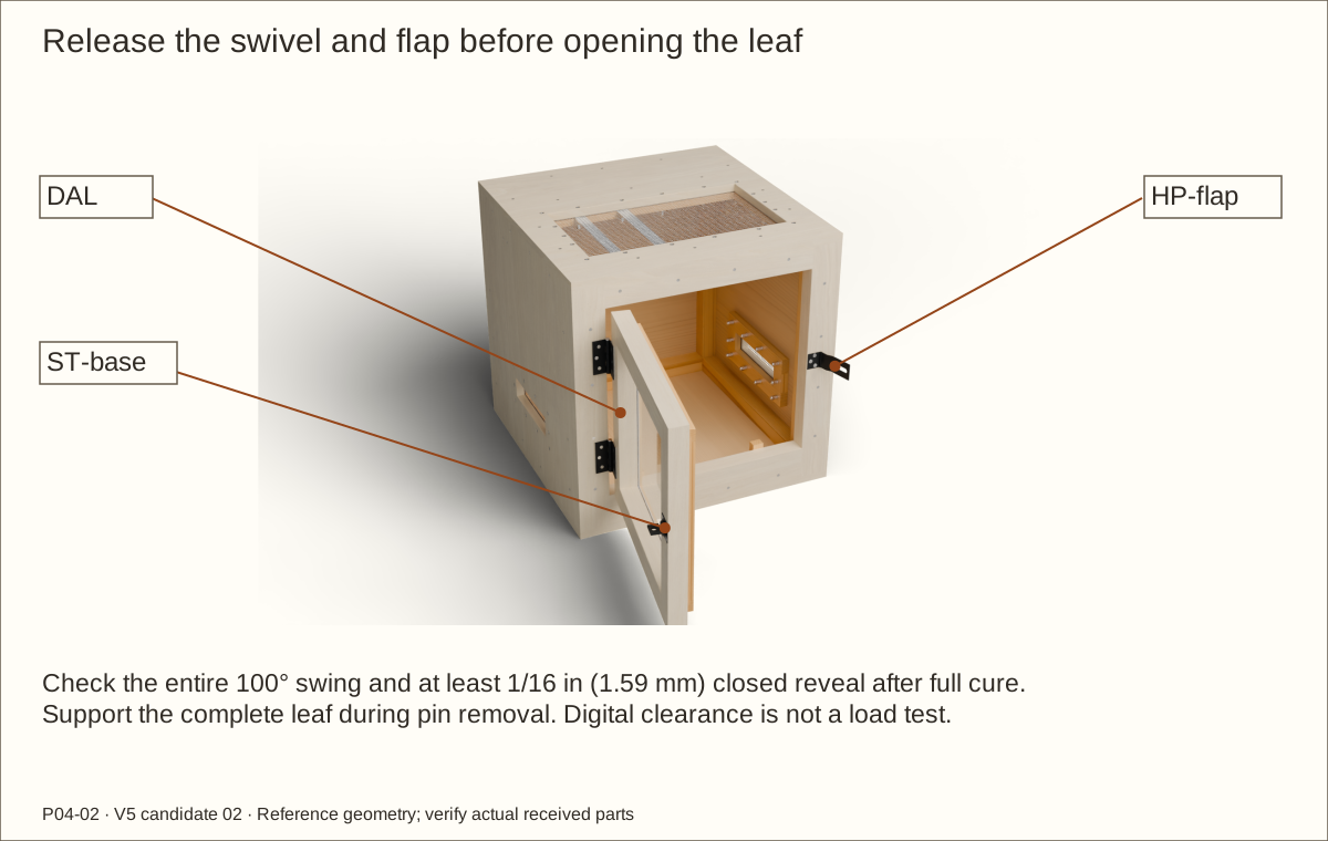
With a helper carrying the leaf weight, move it slowly from closed to 100°. Watch the front latch arris, rear bevel, hinge edges and stops for contact.
Use the maximum 0.046 in (1.17 mm) veneer-stack samples on both opposing faces. Closed hinge/top/bottom gaps calculate to 0.0955 in (2.43 mm) and latch gap to 0.06425 in (1.63 mm). Check the actual whole swing freely after finishing.
If the hinge, hasp footprint or finished gap cannot pass, stop and revise the coordinated construction. Do not force the leaf or shave unsupported latch wood.
Check before continuing: The supported leaf moves freely through its full intended arc and closes evenly.
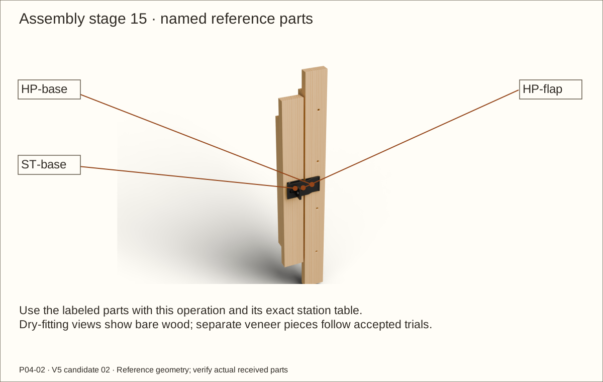
Parts: N305-979 and seven #10 × 5/8 in (15.88 mm) screws
Tools / setup: Tape, square, pencil, clamps and the tools named in the operation
Before you begin: Formed hasp geometry is illustrative; the received hardware is the drilling template.
Fit the independent swivel-staple hasp
Keep the fixed mounting leaf on FAR pointing left, and the swivel plate on DAR at the source center X 20 5/16 in (515.94 mm), Z 12 1/2 in (317.5 mm). Trial the actual folded offsets with the leaf supported.
Trace the real metal bearing footprints and holes. The nominal latch-edge plate margin is only 0.033125 in (0.84 mm) after trim; every plate and hole must remain on sound wood. Leave those seats free of veneer.
Drill stopped pilots and fit the seven specified #10 × 5/8 in (15.88 mm) screws. Turn the staple a quarter-turn, swing the flap fully away, then open the door. Close the flap and turn the staple across its slot to secure.
Check before continuing: The closure operates by hand without a key, binds nowhere and has supported screws.
Parts: Supported leaf and both removable hinge pins
Tools / setup: Tape, square, pencil, clamps and the tools named in the operation
Before you begin: Never allow an unpinned or partly pinned door to carry its own weight.
Prove roof-on pin and door removal
With the roof installed, release the hasp and open the supported door to 90°. Confirm actual total pin length no more than 3 7/16 in (87.31 mm) and head diameter no more than 3/8 in (9.53 mm).
Remove the upper pin first, then the lower while a helper holds the leaf. Lift each only until its tip clears its own barrel, then bring it forward; do not drive a lower pin into the hinge above.
Move the unpinned leaf forward onto a padded bench. Refit lower pin first, then upper, while aligning and supporting the leaf. Repeat after veneer and coating cure.
Check before continuing: Both pins, the complete leaf and the pane-service route are accessible with the roof on.
Parts: LB1/LB2 and actual external screen-top fixture
Tools / setup: Tape, square, pencil, clamps and the tools named in the operation
Before you begin: Do not energize an unaccepted installation; acrylic is not a heat shield or ultraviolet-B delivery method.
Trial the proposed fixture provision
After H07 review, position the proposed fixture center 8 in (203.2 mm) from LEFT and 9 in (228.6 mm) behind FRONT. Its rigid flat rim must be 5 1/2 in (139.7 mm)–6 in (152.4 mm) in diameter, overall diameter no more than 6 in (152.4 mm).
Verify all four stable rim contacts on the two steel strips through mesh. Weigh the complete fixture and bulb; 2 lb (0.91 kg) is the proposed scenario, not a tested roof rating.
Keep the right side free of heat equipment. Follow actual fixture/bulb clearances, independent controls and measured thermal commissioning; equipment is not selected by this generic shell guide.
Check before continuing: Actual contacts, weight and qualified load/thermal disposition are recorded.
Tools / setup: Tape, square, pencil, clamps and the tools named in the operation
Label and dismantle for finishing
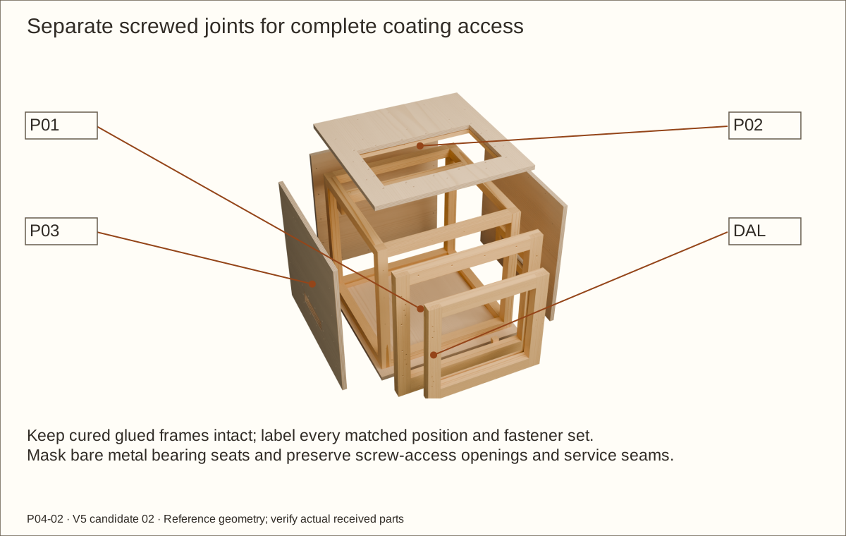
Photograph and label all matched positions. Remove the supported leaf, roof, mesh, metal and glazing trials; dismantle screwed wood joints with helpers while keeping cured glue-ups intact.
Mark each bare hinge/spacer, hasp and flush-head access opening, service screw opening and removable seam. Protect those datums from an added veneer or adhesive layer.
Lay parts flat on clean supports so faces, edges, concealed surfaces and glazing pockets can be prepared. Keep metal filings and sanding dust away from acrylic.
Check before continuing: Every coating surface is accessible and original matched positions are recorded.
Parts: Matched offcuts, chosen PSA veneer, sealer and topcoat
Tools / setup: Tape, square, pencil, clamps and the tools named in the operation
Approve the veneer and finish sample
Make flat-face, edge, reveal, metal-seat and door-gap samples with the supplier-approved system. Confirm panel balance and the actual indoor moisture/cleaner exposure.
Measure the complete cured veneer/backing/adhesive/coating stack: reference 0.0305 in (0.77 mm) and maximum 0.046 in (1.17 mm). Inspect for weak bond, lifting edges or bow after the required dwell.
Record the supplier’s acclimation, application pressure, sealer cure and adhesive dwell. No universal numerical PSA wait is invented; a balancing layer or failed sample requires revised construction.
Check before continuing: H03/H06 acceptance, measured stack and required waits are recorded.
Required wait: Supplier-specified acclimation and adhesive dwell plus full coating cure before accepting the sample.
Parts: All intended wood faces; approved coating system
Tools / setup: Tape, square, pencil, clamps and the tools named in the operation
Before you begin: Resolve the maker’s floor-use exclusion for this enclosure floor before coating it. No immersed-use or animal-safety approval is implied.
Prepare, seal and cure the wood
Sand clean dry wood from 120 through 220 grit, vacuum and wipe with a clean lint-free cloth. Mask future glue faces and specified bare metal bearing seats.
For the selected Varathane Triple Thick satin, stir rather than shake; apply its uniform coat along the grain with a synthetic-bristle brush at 60–90°F (16–32°C), below 85% relative humidity, with ventilation. Follow the accepted PSA-substrate sequence.
The conservative coating allowance is 110.63 ft² (10.28 m²), including veneer and trial. Three quarts are required at the 50 ft² (4.65 m²) per-quart basis; buy two two-quart packs. The extra contingency is this plan’s reserve, not a second manufacturer requirement.
Check before continuing: Required faces and concealed edges are treated without flooding fits.
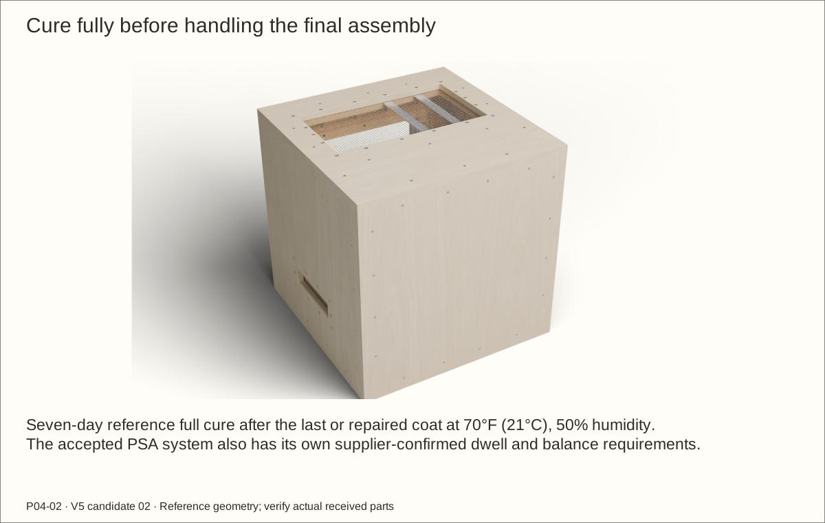
Required wait: Seven-day reference full cure after the final/repair coat at 70°F (21°C), 50% relative humidity; extend for adverse conditions and approved veneer preparation.
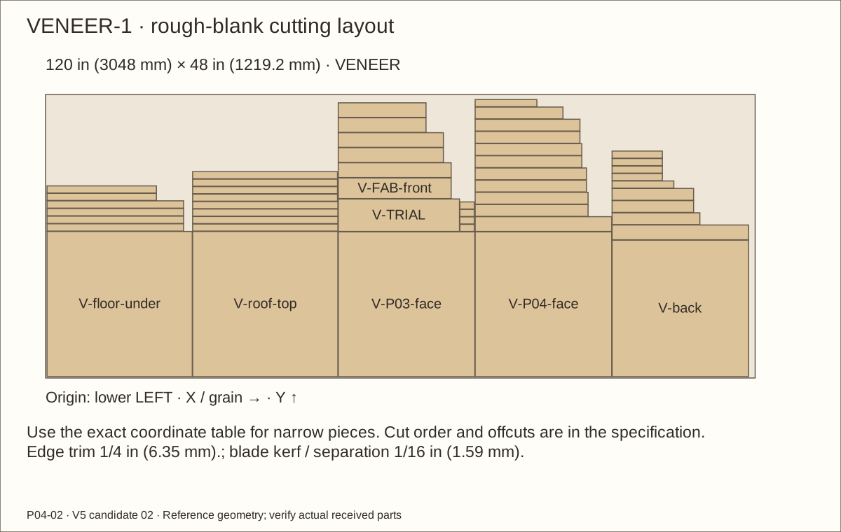
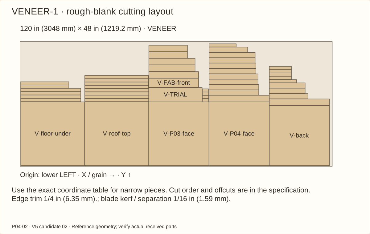
Follow VENEER-1 and its coordinate table. Buy one species, not three complete sets. Keep the scheduled grain direction, rough trimming allowances and separate trial piece.
With backing intact, cut rough blanks on a sacrificial surface using a sharp knife and straightedge. Label each V-ID, parent wood part and grain direction.
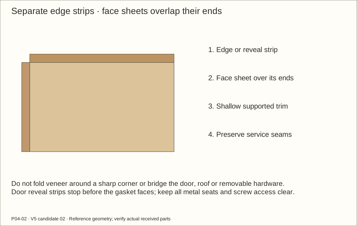
Sort face sheets, edge strips and opening reveals. The roof, underside, sides, back, front and all exposed wooden edges receive named pieces; no strip bridges a removable joint.
Check before continuing: All forty-nine pieces are allocated with the same chosen species.
Dry-position each strip and follow the supplier’s surface preparation and pressure instructions. Apply the recommended firm scraper pressure without trapping air.
Use separate strips for square corners. Support the fibers with a block, flush-trim in shallow passes and ease sharp edges lightly; do not fold a flat strip around a sharp arris.
Cover roof/side opening reveals and door edges. Door viewing reveals end at the rear face before gasket bearing surfaces; keep the glazing pocket and all bare metal seats free. Preserve separate roof and door seams.
Check before continuing: Exposed edges are covered while all bearing datums and removable joints remain clear.
Required wait: Observe the confirmed adhesive dwell before loading or coating the bond.
43. Apply matching faces and preserve hardware access
Parts: V-face sheets and actual hardware templates
Tools / setup: Tape, square, pencil, clamps and the tools named in the operation
Apply matching faces and preserve hardware access
Apply each sheet in the recorded grain direction. Face sheets meet or cover the ends of the edge strips as drawn; trim without gouging the underlying wood.
Cover the roof top, floor underside, sides, back, frame and door fronts. Keep grain straight at physical scale, including a continuous width direction over the roof front edge.
Transfer and open the scheduled metal bearing footprints and screw-head service holes. Metal remains on its original wood datum or solid hinge spacer; do not conceal a removable screw under veneer.
Check before continuing: The visible wooden exterior is uniform and service access remains available.
Required wait: Supplier-confirmed dwell before topcoating or assembly.
Tools / setup: Tape, square, pencil, clamps and the tools named in the operation
Topcoat and record the full cure
After the accepted adhesive dwell, apply the compatible finish along the grain. Check narrow reveals, corners, masked seats and removable seams for runs or bridges.
For this one-coat Varathane formula, add a further coat only when needed and count the added area. Sand with 220 grit first; the reference recoat wait is two hours under the maker’s stated conditions.
Record the last coat time, temperature and relative humidity. Touch-dry, lack of odor and 48-hour light-use timing do not establish full cure; inspect bond and flatness again after cure.
Check before continuing: The finish is uniform, fully cured and free of lifted veneer or bridged joints.
Required wait: At least seven days after the final or repaired coat at 70°F (21°C), 50% relative humidity, longer as conditions or current instructions require.
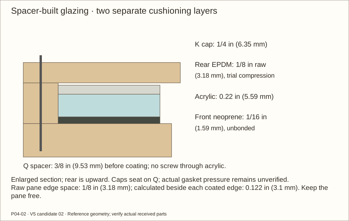
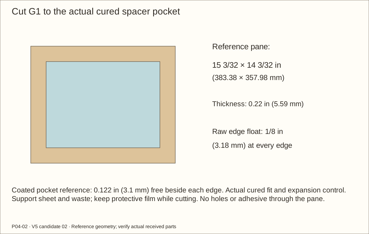
At room temperature measure the pocket inside the coated Q spacers. The reference un-drilled pane is 15 3/32 in (383.38 mm) × 14 3/32 in (357.98 mm) × 0.22 in (5.59 mm), with 1/8 in (3.18 mm) raw edge float and a calculated 0.122 in (3.1 mm) beside each coated pocket edge.
Keep protective film during cutting. Use a supported guided saw and blade suitable for acrylic, with a backed edge and controlled feed to avoid melting or chipping. Follow the sheet maker’s fabrication guide; do not force a score-and-snap method for this thickness.
Deburr without reducing the edge allowance, clean with an acrylic-compatible method and dry-fit freely. Do not drill holes, glue the pane or clamp it to correct a warped leaf.
Check before continuing: The pane lies flat with free expansion space and no cracks or binding.
Tools / setup: Tape, square, pencil, clamps and the tools named in the operation
Before you begin: Exact gasket/adhesive/acrylic compatibility and contact exposure remain H04.
Cut and trial both gasket layers
For EACH layer cut two 15 3/32 in (383.38 mm) horizontal strips and two 13 11/32 in (338.93 mm) vertical strips, all 3/8 in (9.53 mm) wide. Front solid neoprene is 1/16 in (1.59 mm) thick; rear EPDM is 1/8 in (3.18 mm) before compression.
Butt corners without overlapping. Place the solid front gasket unbonded against the cured door face; place rear-strip adhesive on the fully cured cap, away from acrylic. Follow the weatherstrip’s clean/dry preparation and application-temperature instructions.
Trial the actual coated stack. The coated 3/8 in (9.53 mm) spacer gives a nominal 0.381 in (9.68 mm) stand-off and 0.0985 in (2.5 mm) rear-cushion space, about 21.2% compression. This calculation is not pressure measurement or exact foam/adhesive approval.
Check before continuing: The sample seats without bow, rattle, hard points or exposed adhesive.
Required wait: Follow the actual adhesive’s stated bonding conditions before loading the strip.
Tools / setup: Tape, square, pencil, clamps and the tools named in the operation
Reassemble the cured shell and screens
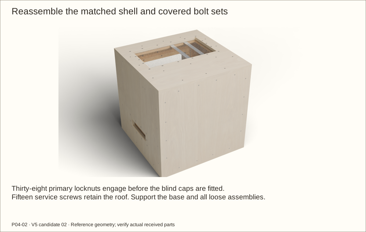
Reassemble the labeled parts in the same braced sequence, checking diagonals and real finished contact. Keep bare metal seats, screw holes and removable seams clear.
Refit all three screens and steel strips with outside flush heads and one interior washer, locknut and closed cover per screw. Check wood lands, open cells, measured tails and cap seating again. Assemble the roof screen on the padded bench; finishing must not change the measured grip.
Fit the roof with its fifteen service screws and verify capture clearance. Keep the leaf on the bench until glazing is complete; recheck the planned full-base support.
Check before continuing: The finished shell is square, stable, fully supported and serviceable.
Parts: Door, Q spacers, gaskets, G1, K caps and fourteen screws
Tools / setup: Tape, square, pencil, clamps and the tools named in the operation
Before you begin: A failed actual gasket sample must be resolved before final assembly.
Capture the pane on a padded bench
Lay the leaf front-down on a clean padded level bench. Place the unbonded front gasket, center the acrylic with equal edge allowance, then position the rear cushion and four caps.
Fit the fourteen cap screws progressively and evenly with a hand driver. Caps must seat on the spacers without using extra torque to bend or pressure the acrylic.
Check for hard spots, bow, rattle and unobstructed edge float. Remove protective film when clean assembly is ready. Keep the caps screwed and removable for future pane service.
Check before continuing: The pane is retained evenly and can be removed without bending or destroying the door.
49. Hang the glazed leaf and check final operation
Parts: Complete leaf, hinges, spacers, pins and hasp
Tools / setup: Tape, square, pencil, clamps and the tools named in the operation
Before you begin: Digital motion does not establish actual hinge capacity or finished fit.
Hang the glazed leaf and check final operation
With helpers supporting the glazed leaf, align the hinge knuckles and insert the lower pin first, then the upper. Confirm full seating without hammering a misaligned hinge.
Release the staple and flap, move slowly through the complete 100° arc and close against both stops. Measure at least 1/16 in (1.59 mm) closed reveal at every point; check free swing, plate support and no veneer bridging.
Repeat roof-on pin withdrawal, leaf removal and reinstall with controlled support. Check the hasp by hand and inspect screw seating after the actual loaded trial.
Check before continuing: The finished glazed leaf opens, closes, secures and removes without binding.
Parts: Complete empty enclosure and documented equipment plan
Tools / setup: Tape, square, pencil, clamps and the tools named in the operation
Before you begin: No animal use is approved by a picture, PDF or passed digital check.
Commission the empty enclosure
Inspect every interior surface for exposed points, sharp wire, loose pieces and incomplete finish. Mark maximum dry substrate 2 1/2 in (63.5 mm) above the finished floor; the inlet remains about 2.5275 in (64.2 mm) above that line at reference veneer/film.
Keep both exterior sides and inner inlet areas at least 2 in (50.8 mm) clear. Verify the animal-specific containment, ventilation, equipment, heat/lighting and maintenance plan separately; this generic build selects no animal.
Record prototype construction, physical load/stability/service tests, environmental measurements and qualified review as separate outcomes. Resolve H01–H07 before putting the enclosure into service.
Check before continuing: All commissioning records and holds have explicit dispositions.
Tools / setup: Tape, square, pencil, clamps and the tools named in the operation
Before you begin: Follow compatible cleaner instructions and inspect veneer bonds, corrosion, gaskets and fasteners regularly.
Service the roof, screens and glazing
Remove the animal to suitable temporary housing and disconnect/cool equipment before service. Keep the entire base supported. Support the roof while removing its fifteen screws, then lift the complete roof assembly.
Release the hasp and remove the supported leaf by upper then lower pins. On a padded bench remove fourteen cap screws, lift the caps/cushions and then the floating pane. Do not flex acrylic out of a fixed frame.
With the roof on a padded bench or the single leaf supported open for side access, support mesh and capture. Hold the outside head with a 1/8 in (3.18 mm) hex key. Hold the inside locknut with a slim 3/8 in (9.53 mm) wrench while removing the cap with a second wrench; then remove nut and washer. Control sharp mesh edges. Refit all thirty-eight sets and repeat the bearing, tail, two-thread, no-bottoming, gap and commissioning checks.
Check before continuing: Every maintained component returns to its checked condition before reuse.
Choose ONE veneer species: one 48 × 120 in (1219.2 × 3048 mm) sheet. Two wide pine boards supply parts; a third is dedicated to trials. Three solid square-pine sticks supply the supports. Two two-quart coating packs provide four quart cans. Resolve H01–H07 first; no local inventory or complete affiliate cart is verified.
Kerf-aware own-panel layouts use a true 48 in (1219.2 mm) × 96 in (2438.4 mm) sheet basis with trim; no oversized nominal-sheet assumption. Uniform 11/16 in (17.46 mm) – 23/32 in (18.26 mm) plywood, actual offcut gauges and fitted dependent parts.
L51144618 Needed 3; 1 per package; buy 3 package(s)
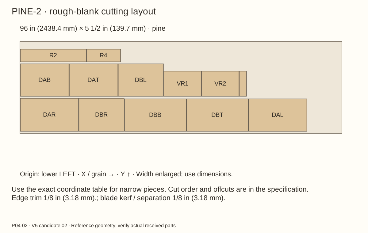
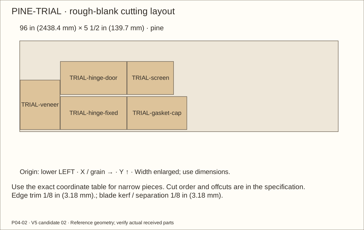
Numbered production layouts plus one dedicated trial board; 3/4 × 5½ × 96 in (2438.4 mm) stock. RB1/RB2 each use two 3/4 in (19.05 mm) blanks; keep glue joints unstressed at least 24 hours.
Thirteen solid 1½-inch-square cleats; no laminated cleat substitution. Three-way fitting uses actual plywood offcut gauges. Numbered layouts include end trim and kerfs.
Materials and hardware · continued
Choose ONE veneer species: one 48 × 120 in (1219.2 × 3048 mm) sheet. Two wide pine boards supply parts; a third is dedicated to trials. Three solid square-pine sticks supply the supports. Two two-quart coating packs provide four quart cans. Resolve H01–H07 first; no local inventory or complete affiliate cart is verified.
C38X2IWPPS 3 Needed 2; 1 per package; buy 2 package(s)
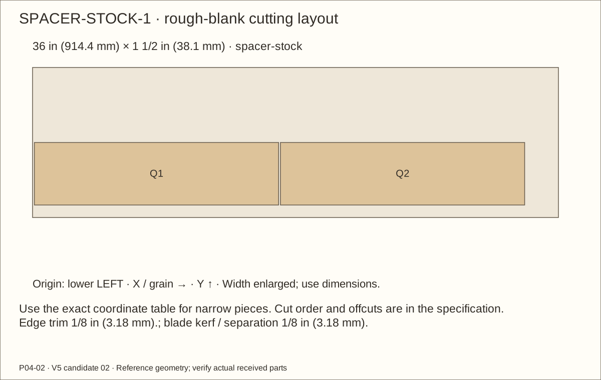
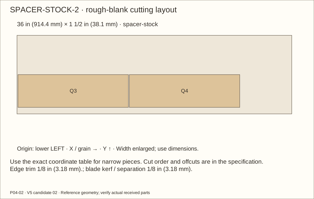
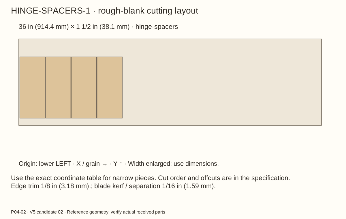
Q1–Q4: rip long stock to 5/8 in (15.88 mm) width, then crosscut. No resawing or thickness machining. SPACER-STOCK-1 supplies Q1 and Q2; SPACER-STOCK-2 supplies Q3 and Q4. Follow the kerf-aware positions in those layouts. Measure received thickness and trial the coated pocket using the actual-stock worksheet.
L5201424 Needed 2; 1 per package; buy 2 package(s)
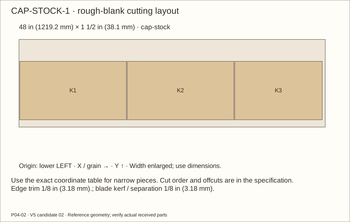
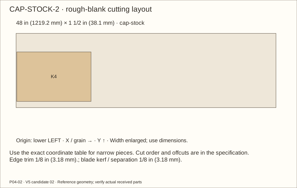
K1–K4: rip long stock to 1 in (25.4 mm) width, then crosscut. No resawing or thickness machining. CAP-STOCK-1 supplies K1, K2 and K3; CAP-STOCK-2 supplies K4. Follow the kerf-aware positions in those layouts. Nominal installed envelope is unchanged; pine-colored model is schematic.
21232102 Needed 1; 1 per package; buy 1 package(s)
One un-drilled 15 3/32 in (383.38 mm) × 14 3/32 in (357.98 mm) × 0.22 in (5.59 mm) pane in the original spacer-and-cap pocket; retain ⅛-inch bare edge float, reduced by cured film. No veneer on gasket bearing face.
Materials and hardware · continued
Choose ONE veneer species: one 48 × 120 in (1219.2 × 3048 mm) sheet. Two wide pine boards supply parts; a third is dedicated to trials. Three solid square-pine sticks supply the supports. Two two-quart coating packs provide four quart cans. Resolve H01–H07 first; no local inventory or complete affiliate cart is verified.
Retain ¼-inch clear aperture; current listing gauge is invalid zero. Model reference 0.025 in (0.64 mm) round wire at 0.275 in (6.99 mm) pitch is an assumption to be replaced by receiving measurements. Maximum welded crossing 1/16 in (1.59 mm); test pockets with cured film and align bolts through actual open cells.
35054 Needed 58; 100 per package; buy 1 package(s)
Use the step marking tables. Received head/root diameters determine pilot and countersink. Hardware kit screws are separate. Includes twelve hinge screws in addition to46 wood-joint screws.
Materials and hardware · continued
Choose ONE veneer species: one 48 × 120 in (1219.2 × 3048 mm) sheet. Two wide pine boards supply parts; a third is dedicated to trials. Three solid square-pine sticks supply the supports. Two two-quart coating packs provide four quart cans. Resolve H01–H07 first; no local inventory or complete affiliate cart is verified.
Thirty-eight #10-24 × 2 in (50.8 mm) socket flat-head screws, 82-degree head, 1/8 in (3.18 mm) hex drive. Outside head seats flush in bare wood. Length includes head; fitted 1 7/8 in (47.63 mm) is only a reference. Actual grip plus washer plus nut plus 7/64 in (2.78 mm) – 9/64 in (3.57 mm) protected tail determines final length. Verify threads reach the entire nut and cover. Cut removed screws in a vise, file ≤1/64 in (0.4 mm) chamfer, refit. Four roof screws retain the recessed steel strips.
Materials and hardware · continued
Choose ONE veneer species: one 48 × 120 in (1219.2 × 3048 mm) sheet. Two wide pine boards supply parts; a third is dedicated to trials. Three solid square-pine sticks supply the supports. Two two-quart coating packs provide four quart cans. Resolve H01–H07 first; no local inventory or complete affiliate cart is verified.
Thirty-eight washers, one between each interior capture and locknut. Published OD 7/16 in (11.11 mm) and ID 7/32 in (5.56 mm); thickness unpublished. Reference 0.05 in (1.27 mm), receive no more than 1/16 in (1.59 mm) and calculate actual fitted screw length. No exterior washer.
Thirty-eight interior nylon-insert locknuts; 3/8 in (9.53 mm) flats, listed height 0.229 in (5.82 mm) – 0.249 in (6.32 mm). Locknut is primary retention. Fit slowly by hand; stop for binding/galling. Do not use an impact driver. Follow supplier advice on compatible lubricant only after animal/contact and finish compatibility review. Fixture temperature, clamping and connection capacity remain H07.
91855A450 Needed 38; 10 per package; buy 4 package(s)
Thirty-eight 18-8 stainless closed-end #10-24 tip covers; buy four packs of ten. Published blind depth 3/16 in (4.76 mm), height 13/32 in (10.32 mm), flats 3/8 in (9.53 mm). Cover seats against the locknut without bottoming. Hold the locknut stationary with a second wrench while snugging the cover. Minimum two full threads after chamfer; cap remains removable. Check tightness and snag safety after service.
Materials and hardware · continued
Choose ONE veneer species: one 48 × 120 in (1219.2 × 3048 mm) sheet. Two wide pine boards supply parts; a third is dedicated to trials. Three solid square-pine sticks supply the supports. Two two-quart coating packs provide four quart cans. Resolve H01–H07 first; no local inventory or complete affiliate cart is verified.
30-004-062-012-036 Needed 1; 1 per package; buy 1 package(s)
Cut 3/8 in (9.53 mm)-wide strips. Captured unbonded between coated wood and pane; no exposed adhesive. Industrial gasket, no animal-exposure certification claimed.
Test the received gasket in the fully cured sample. Four strips total 56 7/8 in (1444.63 mm). Adhesive faces fully cured wood, away from acrylic. OPTIX supports EPDM contact at material-class level; exact foam/adhesive performance is unmeasured. Nominal finished rear space 0.0985 in (2.5 mm) gives 21.2% compression, not measured pressure. Test actual cured stack for cap seating without bow, hard points or rattle. Address-specific availability is unconfirmed.
Raw wood laminations only; mechanically fastened shell. Manufacturer excludes structural/load-bearing use and continuous immersion; no animal safety inferred.
Materials and hardware · continued
Choose ONE veneer species: one 48 × 120 in (1219.2 × 3048 mm) sheet. Two wide pine boards supply parts; a third is dedicated to trials. Three solid square-pine sticks supply the supports. Two two-quart coating packs provide four quart cans. Resolve H01–H07 first; no local inventory or complete affiliate cart is verified.
284473-7482 Needed 3; 2 per package; buy 2 package(s)
110.63 square feet including trial/contingency; 3 quarts required. Two one-quart cans per pack. Follow manufacturer conditions and at least seven-day full cure. Manufacturer excludes floors: enclosure floor abrasion, exposure and cleaner approval remain H06.
hasp · National Hardware black swivel-staple safety hasp, 3-1/4 inch Direct product listing
N305-979 Needed 1; 1 per package; buy 1 package(s)
One independent hasp retained at its own source datum, seven #10 × ⅝-inch screws. Reference plate-to-new-wood latch margin 0.033125 in (0.84 mm); received plate and holes must remain fully supported.
Trial actual flat heads in the hardware countersinks; use a stopped pilot and hand-tighten. Minimum 1/16 in (1.59 mm) rear wood cover.
Materials and hardware · continued
Choose ONE veneer species: one 48 × 120 in (1219.2 × 3048 mm) sheet. Two wide pine boards supply parts; a third is dedicated to trials. Three solid square-pine sticks supply the supports. Two two-quart coating packs provide four quart cans. Resolve H01–H07 first; no local inventory or complete affiliate cart is verified.
Two 11½ × 1 × ⅛-inch strips at the own-source positions; four reference holes updated to the quarter-inch open-cell grid. Supported 2-pound provision is untested, no load/thermal rating.
hinge-spacers · Everbilt solid aluminium flat bar, 1-1/2 × 36 × 1/8 inch Direct product listing
6215 Needed 1; 1 per package; buy 1 package(s)
Four 3 in (76.2 mm) × 1 1/16 in (26.99 mm) × 1/8 in (3.18 mm) full-leaf aluminium spacers; actual manufacturer leaf footprint controls. H01 mounting acceptance open.
Full exterior faces, roof, edges, reveals and trial. Written balance, substrate/finish and service-environment acceptance required.
Materials and hardware · continued
Choose ONE veneer species: one 48 × 120 in (1219.2 × 3048 mm) sheet. Two wide pine boards supply parts; a third is dedicated to trials. Three solid square-pine sticks supply the supports. Two two-quart coating packs provide four quart cans. Resolve H01–H07 first; no local inventory or complete affiliate cart is verified.
Full exterior faces, roof, edges, reveals and trial. Written balance, substrate/finish and service-environment acceptance required.
Cut list
Cut list
One of each ID. Length follows the allocated grain. Rough blanks include trimming; finished sizes describe the reference assembly. V-parts represent the complete cured veneer stack. Field-fit dependent lengths to received stock and finished pockets.
Part
Rough length × width
Finished length × width × thickness
P01 · Floor
24 1/8 in (612.78 mm) × 24 in (609.6 mm)
24 in (609.6 mm) × 24 in (609.6 mm) × 45/64 in (17.86 mm)
P02 · Roof
24 1/8 in (612.78 mm) × 24 in (609.6 mm)
24 in (609.6 mm) × 24 in (609.6 mm) × 45/64 in (17.86 mm)
P03 · Left side
24 1/8 in (612.78 mm) × 22 19/32 in (573.88 mm)
24 in (609.6 mm) × 22 19/32 in (573.88 mm) × 45/64 in (17.86 mm)
P04 · Right side
24 1/8 in (612.78 mm) × 22 19/32 in (573.88 mm)
24 in (609.6 mm) × 22 19/32 in (573.88 mm) × 45/64 in (17.86 mm)
P05 · Back
22 23/32 in (577.06 mm) × 22 19/32 in (573.88 mm)
22 19/32 in (573.88 mm) × 22 19/32 in (573.88 mm) × 45/64 in (17.86 mm)
C1 · C1 solid square-stock cleat
22 19/32 in (573.88 mm) × 1 1/2 in (38.1 mm)
22 19/32 in (573.88 mm) × 1 1/2 in (38.1 mm) × 1 1/2 in (38.1 mm)
C2 · C2 solid square-stock cleat
22 19/32 in (573.88 mm) × 1 1/2 in (38.1 mm)
22 19/32 in (573.88 mm) × 1 1/2 in (38.1 mm) × 1 1/2 in (38.1 mm)
C3 · C3 solid square-stock cleat
22 19/32 in (573.88 mm) × 1 1/2 in (38.1 mm)
22 19/32 in (573.88 mm) × 1 1/2 in (38.1 mm) × 1 1/2 in (38.1 mm)
C4 · C4 solid square-stock cleat
22 19/32 in (573.88 mm) × 1 1/2 in (38.1 mm)
22 19/32 in (573.88 mm) × 1 1/2 in (38.1 mm) × 1 1/2 in (38.1 mm)
C5 · C5 solid square-stock cleat
18 51/64 in (477.44 mm) × 1 1/2 in (38.1 mm)
18 51/64 in (477.44 mm) × 1 1/2 in (38.1 mm) × 1 1/2 in (38.1 mm)
Cut list · continued
One of each ID. Length follows the allocated grain. Rough blanks include trimming; finished sizes describe the reference assembly. V-parts represent the complete cured veneer stack. Field-fit dependent lengths to received stock and finished pockets.
Part
Rough length × width
Finished length × width × thickness
C6 · C6 solid square-stock cleat
18 51/64 in (477.44 mm) × 1 1/2 in (38.1 mm)
18 51/64 in (477.44 mm) × 1 1/2 in (38.1 mm) × 1 1/2 in (38.1 mm)
C7 · C7 solid square-stock cleat
18 51/64 in (477.44 mm) × 1 1/2 in (38.1 mm)
18 51/64 in (477.44 mm) × 1 1/2 in (38.1 mm) × 1 1/2 in (38.1 mm)
C8 · C8 solid square-stock cleat
18 51/64 in (477.44 mm) × 1 1/2 in (38.1 mm)
18 51/64 in (477.44 mm) × 1 1/2 in (38.1 mm) × 1 1/2 in (38.1 mm)
C9 · C9 solid square-stock cleat
19 19/32 in (497.68 mm) × 1 1/2 in (38.1 mm)
19 19/32 in (497.68 mm) × 1 1/2 in (38.1 mm) × 1 1/2 in (38.1 mm)
C10 · C10 solid square-stock cleat
19 19/32 in (497.68 mm) × 1 1/2 in (38.1 mm)
19 19/32 in (497.68 mm) × 1 1/2 in (38.1 mm) × 1 1/2 in (38.1 mm)
C11 · C11 solid square-stock cleat
19 19/32 in (497.68 mm) × 1 1/2 in (38.1 mm)
19 19/32 in (497.68 mm) × 1 1/2 in (38.1 mm) × 1 1/2 in (38.1 mm)
C12 · C12 solid square-stock cleat
19 19/32 in (497.68 mm) × 1 1/2 in (38.1 mm)
19 19/32 in (497.68 mm) × 1 1/2 in (38.1 mm) × 1 1/2 in (38.1 mm)
C13 · C13 solid square-stock cleat
19 19/32 in (497.68 mm) × 1 1/2 in (38.1 mm)
19 19/32 in (497.68 mm) × 1 1/2 in (38.1 mm) × 1 1/2 in (38.1 mm)
RB1-A · Roof rib bearing block lamination blank
2 3/8 in (60.33 mm) × 2 in (50.8 mm)
2 1/4 in (57.15 mm) × 2 in (50.8 mm) × 3/4 in (19.05 mm)
RB1-B · Roof rib bearing block lamination blank
2 3/8 in (60.33 mm) × 2 in (50.8 mm)
2 1/4 in (57.15 mm) × 2 in (50.8 mm) × 3/4 in (19.05 mm)
Cut list · continued
One of each ID. Length follows the allocated grain. Rough blanks include trimming; finished sizes describe the reference assembly. V-parts represent the complete cured veneer stack. Field-fit dependent lengths to received stock and finished pockets.
Part
Rough length × width
Finished length × width × thickness
RB2-A · Roof rib bearing block lamination blank
2 3/8 in (60.33 mm) × 2 in (50.8 mm)
2 1/4 in (57.15 mm) × 2 in (50.8 mm) × 3/4 in (19.05 mm)
RB2-B · Roof rib bearing block lamination blank
2 3/8 in (60.33 mm) × 2 in (50.8 mm)
2 1/4 in (57.15 mm) × 2 in (50.8 mm) × 3/4 in (19.05 mm)
FAL · Front frame A L
22 23/32 in (577.06 mm) × 2 in (50.8 mm)
22 19/32 in (573.88 mm) × 2 in (50.8 mm) × 3/4 in (19.05 mm)
FAR · Front frame A R
22 23/32 in (577.06 mm) × 2 in (50.8 mm)
22 19/32 in (573.88 mm) × 2 in (50.8 mm) × 3/4 in (19.05 mm)
FAB · Front frame A B
18 23/32 in (475.46 mm) × 3 in (76.2 mm)
18 19/32 in (472.28 mm) × 3 in (76.2 mm) × 3/4 in (19.05 mm)
FAT · Front frame A T
18 23/32 in (475.46 mm) × 2 in (50.8 mm)
18 19/32 in (472.28 mm) × 2 in (50.8 mm) × 3/4 in (19.05 mm)
FBL · Front frame B L
17 23/32 in (450.06 mm) × 2 in (50.8 mm)
17 19/32 in (446.88 mm) × 2 in (50.8 mm) × 3/4 in (19.05 mm)
FBR · Front frame B R
17 23/32 in (450.06 mm) × 2 in (50.8 mm)
17 19/32 in (446.88 mm) × 2 in (50.8 mm) × 3/4 in (19.05 mm)
FBB · Front frame B B
22 23/32 in (577.06 mm) × 3 in (76.2 mm)
22 19/32 in (573.88 mm) × 3 in (76.2 mm) × 3/4 in (19.05 mm)
FBT · Front frame B T
22 23/32 in (577.06 mm) × 2 in (50.8 mm)
22 19/32 in (573.88 mm) × 2 in (50.8 mm) × 3/4 in (19.05 mm)
Cut list · continued
One of each ID. Length follows the allocated grain. Rough blanks include trimming; finished sizes describe the reference assembly. V-parts represent the complete cured veneer stack. Field-fit dependent lengths to received stock and finished pockets.
Part
Rough length × width
Finished length × width × thickness
DAL · Door A L
17 11/32 in (440.53 mm) × 1 15/16 in (49.21 mm)
17 7/32 in (437.36 mm) × 1 15/16 in (49.21 mm) × 3/4 in (19.05 mm)
DAR · Door A R
17 11/32 in (440.53 mm) × 1 31/32 in (50.01 mm)
17 7/32 in (437.36 mm) × 1 31/32 in (50.01 mm) × 3/4 in (19.05 mm)
DAB · Door A B
14 15/32 in (367.51 mm) × 1 15/16 in (49.21 mm)
14 11/32 in (364.33 mm) × 1 15/16 in (49.21 mm) × 3/4 in (19.05 mm)
DAT · Door A T
14 15/32 in (367.51 mm) × 1 15/16 in (49.21 mm)
14 11/32 in (364.33 mm) × 1 15/16 in (49.21 mm) × 3/4 in (19.05 mm)
DBL · Door B L
13 15/32 in (342.11 mm) × 1 15/16 in (49.21 mm)
13 11/32 in (338.93 mm) × 1 15/16 in (49.21 mm) × 3/4 in (19.05 mm)
DBR · Door B R
13 15/32 in (342.11 mm) × 1 31/32 in (50.01 mm)
13 11/32 in (338.93 mm) × 1 31/32 in (50.01 mm) × 3/4 in (19.05 mm)
DBB · Door B B
18 3/8 in (466.73 mm) × 1 15/16 in (49.21 mm)
18 1/4 in (463.55 mm) × 1 15/16 in (49.21 mm) × 3/4 in (19.05 mm)
DBT · Door B T
18 3/8 in (466.73 mm) × 1 15/16 in (49.21 mm)
18 1/4 in (463.55 mm) × 1 15/16 in (49.21 mm) × 3/4 in (19.05 mm)
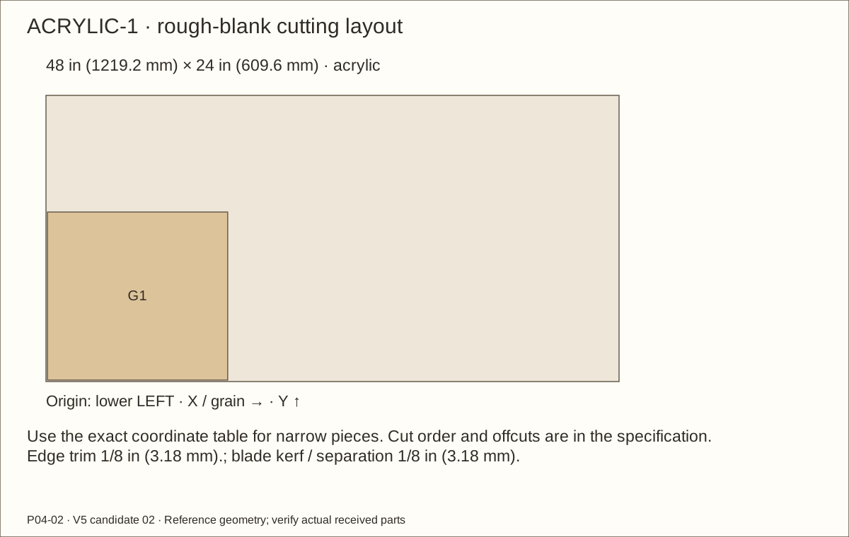
G1 · Captured clear acrylic
15 3/32 in (383.38 mm) × 14 3/32 in (357.98 mm)
15 3/32 in (383.38 mm) × 14 3/32 in (357.98 mm) × 0.22 in (5.59 mm)
GF1 · Front solid neoprene
15 3/32 in (383.38 mm) × 3/8 in (9.53 mm)
15 3/32 in (383.38 mm) × 3/8 in (9.53 mm) × 1/16 in (1.59 mm)
Cut list · continued
One of each ID. Length follows the allocated grain. Rough blanks include trimming; finished sizes describe the reference assembly. V-parts represent the complete cured veneer stack. Field-fit dependent lengths to received stock and finished pockets.
Part
Rough length × width
Finished length × width × thickness
GF2 · Front solid neoprene
15 3/32 in (383.38 mm) × 3/8 in (9.53 mm)
15 3/32 in (383.38 mm) × 3/8 in (9.53 mm) × 1/16 in (1.59 mm)
GF3 · Front solid neoprene
13 11/32 in (338.93 mm) × 3/8 in (9.53 mm)
13 11/32 in (338.93 mm) × 3/8 in (9.53 mm) × 1/16 in (1.59 mm)
GF4 · Front solid neoprene
13 11/32 in (338.93 mm) × 3/8 in (9.53 mm)
13 11/32 in (338.93 mm) × 3/8 in (9.53 mm) × 1/16 in (1.59 mm)
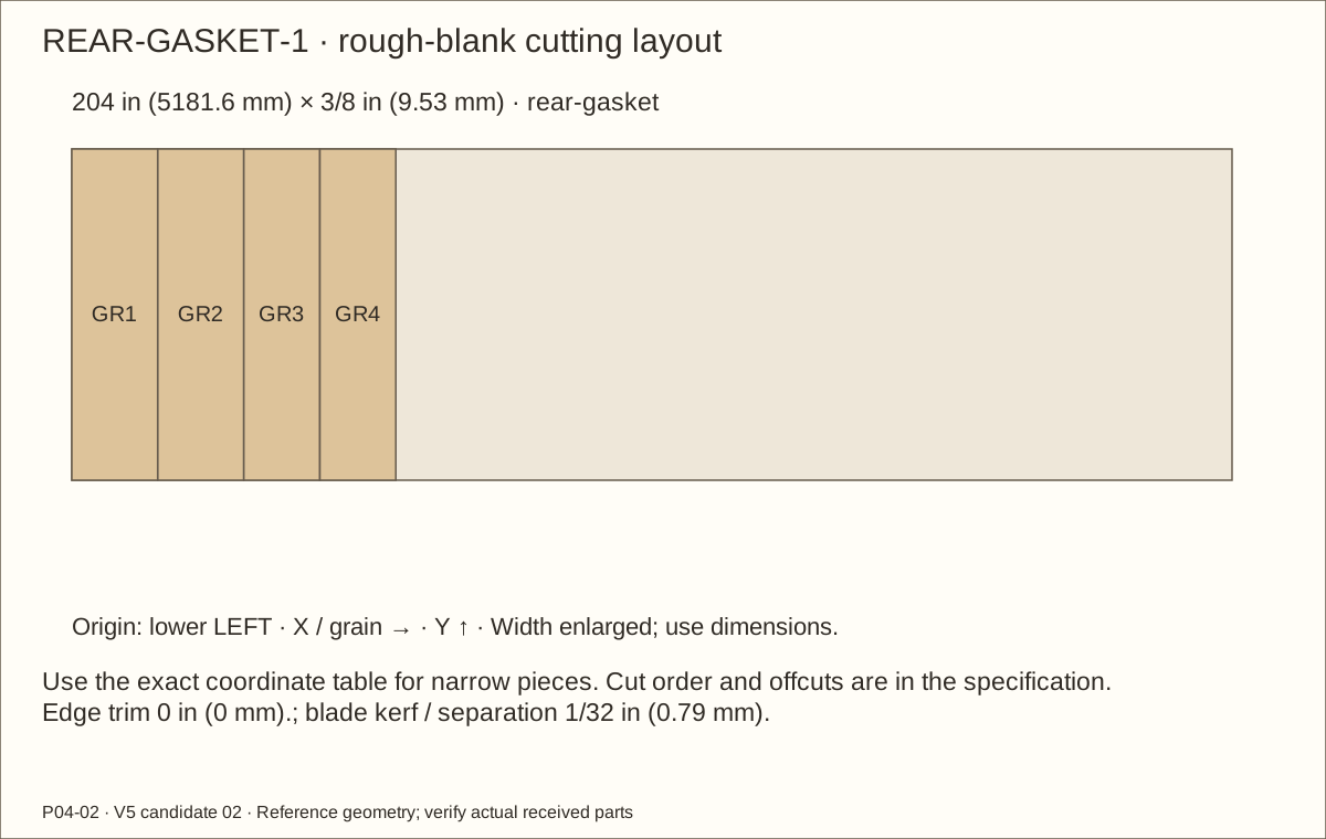
GR1 · Rear ribbed EPDM V23WA (cut 1/8 thick)
15 3/32 in (383.38 mm) × 3/8 in (9.53 mm)
15 3/32 in (383.38 mm) × 3/8 in (9.53 mm) × 1/8 in (3.18 mm)
GR2 · Rear ribbed EPDM V23WA (cut 1/8 thick)
15 3/32 in (383.38 mm) × 3/8 in (9.53 mm)
15 3/32 in (383.38 mm) × 3/8 in (9.53 mm) × 1/8 in (3.18 mm)
GR3 · Rear ribbed EPDM V23WA (cut 1/8 thick)
13 11/32 in (338.93 mm) × 3/8 in (9.53 mm)
13 11/32 in (338.93 mm) × 3/8 in (9.53 mm) × 1/8 in (3.18 mm)
GR4 · Rear ribbed EPDM V23WA (cut 1/8 thick)
13 11/32 in (338.93 mm) × 3/8 in (9.53 mm)
13 11/32 in (338.93 mm) × 3/8 in (9.53 mm) × 1/8 in (3.18 mm)
Q1 · Glazing spacer 1
16 23/32 in (424.66 mm) × 5/8 in (15.88 mm)
16 19/32 in (421.48 mm) × 5/8 in (15.88 mm) × 3/8 in (9.53 mm)
Q2 · Glazing spacer 2
16 23/32 in (424.66 mm) × 5/8 in (15.88 mm)
16 19/32 in (421.48 mm) × 5/8 in (15.88 mm) × 3/8 in (9.53 mm)
Q3 · Glazing spacer 3
14 15/32 in (367.51 mm) × 5/8 in (15.88 mm)
14 11/32 in (364.33 mm) × 5/8 in (15.88 mm) × 3/8 in (9.53 mm)
Cut list · continued
One of each ID. Length follows the allocated grain. Rough blanks include trimming; finished sizes describe the reference assembly. V-parts represent the complete cured veneer stack. Field-fit dependent lengths to received stock and finished pockets.
Part
Rough length × width
Finished length × width × thickness
Q4 · Glazing spacer 4
14 15/32 in (367.51 mm) × 5/8 in (15.88 mm)
14 11/32 in (364.33 mm) × 5/8 in (15.88 mm) × 3/8 in (9.53 mm)
K1 · Glazing cap 1
16 23/32 in (424.66 mm) × 1 in (25.4 mm)
16 19/32 in (421.48 mm) × 1 in (25.4 mm) × 1/4 in (6.35 mm)
K2 · Glazing cap 2
16 23/32 in (424.66 mm) × 1 in (25.4 mm)
16 19/32 in (421.48 mm) × 1 in (25.4 mm) × 1/4 in (6.35 mm)
K3 · Glazing cap 3
13 23/32 in (348.46 mm) × 1 in (25.4 mm)
13 19/32 in (345.28 mm) × 1 in (25.4 mm) × 1/4 in (6.35 mm)
K4 · Glazing cap 4
13 23/32 in (348.46 mm) × 1 in (25.4 mm)
13 19/32 in (345.28 mm) × 1 in (25.4 mm) × 1/4 in (6.35 mm)
ST1 · Lower door stop
1 1/8 in (28.58 mm) × 1 in (25.4 mm)
1 in (25.4 mm) × 1 in (25.4 mm) × 3/4 in (19.05 mm)
ST2 · Lower door stop
1 1/8 in (28.58 mm) × 1 in (25.4 mm)
1 in (25.4 mm) × 1 in (25.4 mm) × 3/4 in (19.05 mm)
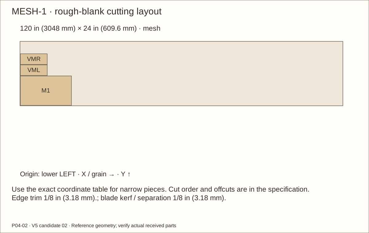
M1 · Roof hardware cloth
19 in (482.6 mm) × 11 in (279.4 mm)
19 in (482.6 mm) × 11 in (279.4 mm) × 1/16 in (1.59 mm)
R1 · Roof screen batten 1
19 5/8 in (498.48 mm) × 3/4 in (19.05 mm)
19 1/2 in (495.3 mm) × 3/4 in (19.05 mm) × 3/4 in (19.05 mm)
R2 · Roof screen batten 2
19 5/8 in (498.48 mm) × 3/4 in (19.05 mm)
19 1/2 in (495.3 mm) × 3/4 in (19.05 mm) × 3/4 in (19.05 mm)
Cut list · continued
One of each ID. Length follows the allocated grain. Rough blanks include trimming; finished sizes describe the reference assembly. V-parts represent the complete cured veneer stack. Field-fit dependent lengths to received stock and finished pockets.
Part
Rough length × width
Finished length × width × thickness
R3 · Roof screen batten 3
10 1/8 in (257.18 mm) × 3/4 in (19.05 mm)
10 in (254 mm) × 3/4 in (19.05 mm) × 3/4 in (19.05 mm)
R4 · Roof screen batten 4
10 1/8 in (257.18 mm) × 3/4 in (19.05 mm)
10 in (254 mm) × 3/4 in (19.05 mm) × 3/4 in (19.05 mm)
VML · L inlet hardware cloth
10 in (254 mm) × 4 in (101.6 mm)
10 in (254 mm) × 4 in (101.6 mm) × 1/16 in (1.59 mm)
VL1 · L inlet batten 1
11 1/8 in (282.58 mm) × 1 1/2 in (38.1 mm)
11 in (279.4 mm) × 1 1/2 in (38.1 mm) × 3/4 in (19.05 mm)
VL2 · L inlet batten 2
11 1/8 in (282.58 mm) × 1 1/2 in (38.1 mm)
11 in (279.4 mm) × 1 1/2 in (38.1 mm) × 3/4 in (19.05 mm)
VL3 · L inlet batten 3
2 1/8 in (53.98 mm) × 1 1/2 in (38.1 mm)
2 in (50.8 mm) × 1 1/2 in (38.1 mm) × 3/4 in (19.05 mm)
VL4 · L inlet batten 4
2 1/8 in (53.98 mm) × 1 1/2 in (38.1 mm)
2 in (50.8 mm) × 1 1/2 in (38.1 mm) × 3/4 in (19.05 mm)
VMR · R inlet hardware cloth
10 in (254 mm) × 4 in (101.6 mm)
10 in (254 mm) × 4 in (101.6 mm) × 1/16 in (1.59 mm)
VR1 · R inlet batten 1
11 1/8 in (282.58 mm) × 1 1/2 in (38.1 mm)
11 in (279.4 mm) × 1 1/2 in (38.1 mm) × 3/4 in (19.05 mm)
VR2 · R inlet batten 2
11 1/8 in (282.58 mm) × 1 1/2 in (38.1 mm)
11 in (279.4 mm) × 1 1/2 in (38.1 mm) × 3/4 in (19.05 mm)
Cut list · continued
One of each ID. Length follows the allocated grain. Rough blanks include trimming; finished sizes describe the reference assembly. V-parts represent the complete cured veneer stack. Field-fit dependent lengths to received stock and finished pockets.
Part
Rough length × width
Finished length × width × thickness
VR3 · R inlet batten 3
2 1/8 in (53.98 mm) × 1 1/2 in (38.1 mm)
2 in (50.8 mm) × 1 1/2 in (38.1 mm) × 3/4 in (19.05 mm)
VR4 · R inlet batten 4
2 1/8 in (53.98 mm) × 1 1/2 in (38.1 mm)
2 in (50.8 mm) × 1 1/2 in (38.1 mm) × 3/4 in (19.05 mm)
LB1 · Steel strip beneath left lamp area
11 1/2 in (292.1 mm) × 1 in (25.4 mm)
11 1/2 in (292.1 mm) × 1 in (25.4 mm) × 1/8 in (3.18 mm)
LB2 · Steel strip beneath left lamp area
11 1/2 in (292.1 mm) × 1 in (25.4 mm)
11 1/2 in (292.1 mm) × 1 in (25.4 mm) × 1/8 in (3.18 mm)
SP-H1-fixed · Full hinge bearing spacer H1 fixed
3 in (76.2 mm) × 1 1/16 in (26.99 mm)
3 in (76.2 mm) × 1 1/16 in (26.99 mm) × 1/8 in (3.18 mm)
SP-H1-moving · Full hinge bearing spacer H1 moving
3 in (76.2 mm) × 1 1/16 in (26.99 mm)
3 in (76.2 mm) × 1 1/16 in (26.99 mm) × 1/8 in (3.18 mm)
SP-H2-fixed · Full hinge bearing spacer H2 fixed
3 in (76.2 mm) × 1 1/16 in (26.99 mm)
3 in (76.2 mm) × 1 1/16 in (26.99 mm) × 1/8 in (3.18 mm)
SP-H2-moving · Full hinge bearing spacer H2 moving
3 in (76.2 mm) × 1 1/16 in (26.99 mm)
3 in (76.2 mm) × 1 1/16 in (26.99 mm) × 1/8 in (3.18 mm)
V-floor-under · Exterior veneer · floor-under
24.561 in (623.85 mm) × 24.561 in (623.85 mm)
24.061 in (611.15 mm) × 24.061 in (611.15 mm) × 0.0305 in (0.77 mm)
V-roof-top · Exterior veneer · roof-top
24.561 in (623.85 mm) × 24.561 in (623.85 mm)
24.061 in (611.15 mm) × 24.061 in (611.15 mm) × 0.0305 in (0.77 mm)
Cut list · continued
One of each ID. Length follows the allocated grain. Rough blanks include trimming; finished sizes describe the reference assembly. V-parts represent the complete cured veneer stack. Field-fit dependent lengths to received stock and finished pockets.
Part
Rough length × width
Finished length × width × thickness
V-P01-front · Exterior veneer · P01-front
24.561 in (623.85 mm) × 1 13/64 in (30.56 mm)
24.061 in (611.15 mm) × 45/64 in (17.86 mm) × 0.0305 in (0.77 mm)
V-P01-back · Exterior veneer · P01-back
24.561 in (623.85 mm) × 1 13/64 in (30.56 mm)
24.061 in (611.15 mm) × 45/64 in (17.86 mm) × 0.0305 in (0.77 mm)
V-P01-left · Exterior veneer · P01-left
24 1/2 in (622.3 mm) × 1 13/64 in (30.56 mm)
24 in (609.6 mm) × 45/64 in (17.86 mm) × 0.0305 in (0.77 mm)
V-P01-right · Exterior veneer · P01-right
24 1/2 in (622.3 mm) × 1 13/64 in (30.56 mm)
24 in (609.6 mm) × 45/64 in (17.86 mm) × 0.0305 in (0.77 mm)
V-P02-front · Exterior veneer · P02-front
24.561 in (623.85 mm) × 1 13/64 in (30.56 mm)
24.061 in (611.15 mm) × 45/64 in (17.86 mm) × 0.0305 in (0.77 mm)
V-P02-back · Exterior veneer · P02-back
24.561 in (623.85 mm) × 1 13/64 in (30.56 mm)
24.061 in (611.15 mm) × 45/64 in (17.86 mm) × 0.0305 in (0.77 mm)
V-P02-left · Exterior veneer · P02-left
24 1/2 in (622.3 mm) × 1 13/64 in (30.56 mm)
24 in (609.6 mm) × 45/64 in (17.86 mm) × 0.0305 in (0.77 mm)
V-P02-right · Exterior veneer · P02-right
24 1/2 in (622.3 mm) × 1 13/64 in (30.56 mm)
24 in (609.6 mm) × 45/64 in (17.86 mm) × 0.0305 in (0.77 mm)
V-P03-face · Exterior veneer · P03-face
23 3/32 in (586.58 mm) × 24 1/2 in (622.3 mm)
22 19/32 in (573.88 mm) × 24 in (609.6 mm) × 0.0305 in (0.77 mm)
V-P03-front · Exterior veneer · P03-front
23 3/32 in (586.58 mm) × 1.233625 in (31.33 mm)
22 19/32 in (573.88 mm) × 0.733625 in (18.63 mm) × 0.0305 in (0.77 mm)
Cut list · continued
One of each ID. Length follows the allocated grain. Rough blanks include trimming; finished sizes describe the reference assembly. V-parts represent the complete cured veneer stack. Field-fit dependent lengths to received stock and finished pockets.
Part
Rough length × width
Finished length × width × thickness
V-P03-back · Exterior veneer · P03-back
23 3/32 in (586.58 mm) × 1.233625 in (31.33 mm)
22 19/32 in (573.88 mm) × 0.733625 in (18.63 mm) × 0.0305 in (0.77 mm)
V-P03-vent-near · Exterior veneer · P03-vent-near
2.439 in (61.95 mm) × 1 13/64 in (30.56 mm)
1.939 in (49.25 mm) × 45/64 in (17.86 mm) × 0.0305 in (0.77 mm)
V-P03-vent-far · Exterior veneer · P03-vent-far
2.439 in (61.95 mm) × 1 13/64 in (30.56 mm)
1.939 in (49.25 mm) × 45/64 in (17.86 mm) × 0.0305 in (0.77 mm)
8 in (203.2 mm) × 45/64 in (17.86 mm) × 0.0305 in (0.77 mm)
V-P03-vent-top · Exterior veneer · P03-vent-top
8 1/2 in (215.9 mm) × 1 13/64 in (30.56 mm)
8 in (203.2 mm) × 45/64 in (17.86 mm) × 0.0305 in (0.77 mm)
V-P04-face · Exterior veneer · P04-face
23 3/32 in (586.58 mm) × 24 1/2 in (622.3 mm)
22 19/32 in (573.88 mm) × 24 in (609.6 mm) × 0.0305 in (0.77 mm)
V-P04-front · Exterior veneer · P04-front
23 3/32 in (586.58 mm) × 1.233625 in (31.33 mm)
22 19/32 in (573.88 mm) × 0.733625 in (18.63 mm) × 0.0305 in (0.77 mm)
V-P04-back · Exterior veneer · P04-back
23 3/32 in (586.58 mm) × 1.233625 in (31.33 mm)
22 19/32 in (573.88 mm) × 0.733625 in (18.63 mm) × 0.0305 in (0.77 mm)
V-P04-vent-near · Exterior veneer · P04-vent-near
2.439 in (61.95 mm) × 1 13/64 in (30.56 mm)
1.939 in (49.25 mm) × 45/64 in (17.86 mm) × 0.0305 in (0.77 mm)
V-P04-vent-far · Exterior veneer · P04-vent-far
2.439 in (61.95 mm) × 1 13/64 in (30.56 mm)
1.939 in (49.25 mm) × 45/64 in (17.86 mm) × 0.0305 in (0.77 mm)
Cut list · continued
One of each ID. Length follows the allocated grain. Rough blanks include trimming; finished sizes describe the reference assembly. V-parts represent the complete cured veneer stack. Field-fit dependent lengths to received stock and finished pockets.
8 in (203.2 mm) × 45/64 in (17.86 mm) × 0.0305 in (0.77 mm)
V-P04-vent-top · Exterior veneer · P04-vent-top
8 1/2 in (215.9 mm) × 1 13/64 in (30.56 mm)
8 in (203.2 mm) × 45/64 in (17.86 mm) × 0.0305 in (0.77 mm)
V-back · Exterior veneer · back
23 3/32 in (586.58 mm) × 23 3/32 in (586.58 mm)
22 19/32 in (573.88 mm) × 22 19/32 in (573.88 mm) × 0.0305 in (0.77 mm)
V-roof-left · Exterior veneer · roof-left
10.439 in (265.15 mm) × 1 13/64 in (30.56 mm)
9.939 in (252.45 mm) × 45/64 in (17.86 mm) × 0.0305 in (0.77 mm)
V-roof-right · Exterior veneer · roof-right
10.439 in (265.15 mm) × 1 13/64 in (30.56 mm)
9.939 in (252.45 mm) × 45/64 in (17.86 mm) × 0.0305 in (0.77 mm)
V-roof-front · Exterior veneer · roof-front
18 1/2 in (469.9 mm) × 1 13/64 in (30.56 mm)
18 in (457.2 mm) × 45/64 in (17.86 mm) × 0.0305 in (0.77 mm)
V-roof-back · Exterior veneer · roof-back
18 1/2 in (469.9 mm) × 1 13/64 in (30.56 mm)
18 in (457.2 mm) × 45/64 in (17.86 mm) × 0.0305 in (0.77 mm)
V-FAL-front · Exterior veneer · FAL-front
23 3/32 in (586.58 mm) × 2 1/2 in (63.5 mm)
22 19/32 in (573.88 mm) × 2 in (50.8 mm) × 0.0305 in (0.77 mm)
V-FAR-front · Exterior veneer · FAR-front
23 3/32 in (586.58 mm) × 2 1/2 in (63.5 mm)
22 19/32 in (573.88 mm) × 2 in (50.8 mm) × 0.0305 in (0.77 mm)
V-FAB-front · Exterior veneer · FAB-front
19 3/32 in (484.98 mm) × 3 1/2 in (88.9 mm)
18 19/32 in (472.28 mm) × 3 in (76.2 mm) × 0.0305 in (0.77 mm)
Cut list · continued
One of each ID. Length follows the allocated grain. Rough blanks include trimming; finished sizes describe the reference assembly. V-parts represent the complete cured veneer stack. Field-fit dependent lengths to received stock and finished pockets.
Part
Rough length × width
Finished length × width × thickness
V-FAT-front · Exterior veneer · FAT-front
19 3/32 in (484.98 mm) × 2 1/2 in (63.5 mm)
18 19/32 in (472.28 mm) × 2 in (50.8 mm) × 0.0305 in (0.77 mm)
V-jamb-left · Exterior veneer · jamb-left
18.03275 in (458.03 mm) × 2 in (50.8 mm)
17.53275 in (445.33 mm) × 1 1/2 in (38.1 mm) × 0.0305 in (0.77 mm)
V-jamb-right · Exterior veneer · jamb-right
18.03275 in (458.03 mm) × 2 in (50.8 mm)
17.53275 in (445.33 mm) × 1 1/2 in (38.1 mm) × 0.0305 in (0.77 mm)
V-sill · Exterior veneer · sill
19 3/32 in (484.98 mm) × 2 in (50.8 mm)
18 19/32 in (472.28 mm) × 1 1/2 in (38.1 mm) × 0.0305 in (0.77 mm)
V-head · Exterior veneer · head
19 3/32 in (484.98 mm) × 2 in (50.8 mm)
18 19/32 in (472.28 mm) × 1 1/2 in (38.1 mm) × 0.0305 in (0.77 mm)
V-DAL-front · Exterior veneer · DAL-front
17.77975 in (451.61 mm) × 2.468 in (62.69 mm)
17.27975 in (438.91 mm) × 1.968 in (49.99 mm) × 0.0305 in (0.77 mm)
V-DAR-front · Exterior veneer · DAR-front
17.77975 in (451.61 mm) × 2.49925 in (63.48 mm)
17.27975 in (438.91 mm) × 1.99925 in (50.78 mm) × 0.0305 in (0.77 mm)
V-DAB-front · Exterior veneer · DAB-front
14 27/32 in (377.03 mm) × 2.468 in (62.69 mm)
14 11/32 in (364.33 mm) × 1.968 in (49.99 mm) × 0.0305 in (0.77 mm)
V-DAT-front · Exterior veneer · DAT-front
14 27/32 in (377.03 mm) × 2.468 in (62.69 mm)
14 11/32 in (364.33 mm) × 1.968 in (49.99 mm) × 0.0305 in (0.77 mm)
17 7/32 in (437.36 mm) × 1 1/2 in (38.1 mm) × 0.0305 in (0.77 mm)
Cut list · continued
One of each ID. Length follows the allocated grain. Rough blanks include trimming; finished sizes describe the reference assembly. V-parts represent the complete cured veneer stack. Field-fit dependent lengths to received stock and finished pockets.
X runs along the stock length; Y across its width, from the illustrated lower-left corner. These are stock coordinates, not assembled fastener positions. Keep every blank labeled.
ID
Stock X / Y
Rough length × width
P01
1/8 in (3.18 mm) / 1/8 in (3.18 mm)
24 1/8 in (612.78 mm) × 24 in (609.6 mm)
P02
24 3/8 in (619.13 mm) / 1/8 in (3.18 mm)
24 1/8 in (612.78 mm) × 24 in (609.6 mm)
P03
1/8 in (3.18 mm) / 24 1/4 in (615.95 mm)
24 1/8 in (612.78 mm) × 22 19/32 in (573.88 mm)
P04
24 3/8 in (619.13 mm) / 24 1/4 in (615.95 mm)
24 1/8 in (612.78 mm) × 22 19/32 in (573.88 mm)
P05
48 5/8 in (1235.08 mm) / 1/8 in (3.18 mm)
22 23/32 in (577.06 mm) × 22 19/32 in (573.88 mm)
Stock 96 in (2438.4 mm) × 48 in (1219.2 mm); Edge trim 1/8 in (3.18 mm).; kerf/separation 1/8 in (3.18 mm). The full cut order and offcuts are in the specification.
PINE-1 · exact rough blank positions
X runs along the stock length; Y across its width, from the illustrated lower-left corner. These are stock coordinates, not assembled fastener positions. Keep every blank labeled.
ID
Stock X / Y
Rough length × width
FBB
1/8 in (3.18 mm) / 1/8 in (3.18 mm)
22 23/32 in (577.06 mm) × 3 in (76.2 mm)
FAL
1/8 in (3.18 mm) / 3 1/4 in (82.55 mm)
22 23/32 in (577.06 mm) × 2 in (50.8 mm)
FAR
22 31/32 in (583.41 mm) / 1/8 in (3.18 mm)
22 23/32 in (577.06 mm) × 2 in (50.8 mm)
FBT
22 31/32 in (583.41 mm) / 2 1/4 in (57.15 mm)
22 23/32 in (577.06 mm) × 2 in (50.8 mm)
R1
22 31/32 in (583.41 mm) / 4 3/8 in (111.13 mm)
19 5/8 in (498.48 mm) × 3/4 in (19.05 mm)
FAB
45 13/16 in (1163.64 mm) / 1/8 in (3.18 mm)
18 23/32 in (475.46 mm) × 3 in (76.2 mm)
FAT
45 13/16 in (1163.64 mm) / 3 1/4 in (82.55 mm)
18 23/32 in (475.46 mm) × 2 in (50.8 mm)
FBL
64 21/32 in (1642.27 mm) / 1/8 in (3.18 mm)
17 23/32 in (450.06 mm) × 2 in (50.8 mm)
FBR
64 21/32 in (1642.27 mm) / 2 1/4 in (57.15 mm)
17 23/32 in (450.06 mm) × 2 in (50.8 mm)
VL1
82 1/2 in (2095.5 mm) / 1/8 in (3.18 mm)
11 1/8 in (282.58 mm) × 1 1/2 in (38.1 mm)
VL2
82 1/2 in (2095.5 mm) / 1 3/4 in (44.45 mm)
11 1/8 in (282.58 mm) × 1 1/2 in (38.1 mm)
R3
64 21/32 in (1642.27 mm) / 4 3/8 in (111.13 mm)
10 1/8 in (257.18 mm) × 3/4 in (19.05 mm)
RB1-A
82 1/2 in (2095.5 mm) / 3 3/8 in (85.73 mm)
2 3/8 in (60.33 mm) × 2 in (50.8 mm)
RB1-B
85 in (2159 mm) / 3 3/8 in (85.73 mm)
2 3/8 in (60.33 mm) × 2 in (50.8 mm)
RB2-A
87 1/2 in (2222.5 mm) / 3 3/8 in (85.73 mm)
2 3/8 in (60.33 mm) × 2 in (50.8 mm)
RB2-B
90 in (2286 mm) / 3 3/8 in (85.73 mm)
2 3/8 in (60.33 mm) × 2 in (50.8 mm)
Stock 96 in (2438.4 mm) × 5 1/2 in (139.7 mm); Edge trim 1/8 in (3.18 mm).; kerf/separation 1/8 in (3.18 mm). The full cut order and offcuts are in the specification.
PINE-1 · exact rough blank positions
X runs along the stock length; Y across its width, from the illustrated lower-left corner. These are stock coordinates, not assembled fastener positions. Keep every blank labeled.
ID
Stock X / Y
Rough length × width
VL3
93 3/4 in (2381.25 mm) / 1/8 in (3.18 mm)
2 1/8 in (53.98 mm) × 1 1/2 in (38.1 mm)
VL4
93 3/4 in (2381.25 mm) / 1 3/4 in (44.45 mm)
2 1/8 in (53.98 mm) × 1 1/2 in (38.1 mm)
VR3
93 3/4 in (2381.25 mm) / 3 3/8 in (85.73 mm)
2 1/8 in (53.98 mm) × 1 1/2 in (38.1 mm)
ST1
42 23/32 in (1085.06 mm) / 4 3/8 in (111.13 mm)
1 1/8 in (28.58 mm) × 1 in (25.4 mm)
ST2
74 29/32 in (1902.62 mm) / 4 3/8 in (111.13 mm)
1 1/8 in (28.58 mm) × 1 in (25.4 mm)
Stock 96 in (2438.4 mm) × 5 1/2 in (139.7 mm); Edge trim 1/8 in (3.18 mm).; kerf/separation 1/8 in (3.18 mm). The full cut order and offcuts are in the specification.
PINE-2 · exact rough blank positions
X runs along the stock length; Y across its width, from the illustrated lower-left corner. These are stock coordinates, not assembled fastener positions. Keep every blank labeled.
ID
Stock X / Y
Rough length × width
DAR
1/8 in (3.18 mm) / 1/8 in (3.18 mm)
17 11/32 in (440.53 mm) × 1 31/32 in (50.01 mm)
DBR
17 19/32 in (446.88 mm) / 1/8 in (3.18 mm)
13 15/32 in (342.11 mm) × 1 31/32 in (50.01 mm)
DBB
31 3/16 in (792.16 mm) / 1/8 in (3.18 mm)
18 3/8 in (466.73 mm) × 1 15/16 in (49.21 mm)
DBT
49 11/16 in (1262.06 mm) / 1/8 in (3.18 mm)
18 3/8 in (466.73 mm) × 1 15/16 in (49.21 mm)
DAL
68 3/16 in (1731.96 mm) / 1/8 in (3.18 mm)
17 11/32 in (440.53 mm) × 1 15/16 in (49.21 mm)
DAB
1/8 in (3.18 mm) / 2 7/32 in (56.36 mm)
14 15/32 in (367.51 mm) × 1 15/16 in (49.21 mm)
DAT
14 23/32 in (373.86 mm) / 2 7/32 in (56.36 mm)
14 15/32 in (367.51 mm) × 1 15/16 in (49.21 mm)
DBL
29 5/16 in (744.54 mm) / 2 7/32 in (56.36 mm)
13 15/32 in (342.11 mm) × 1 15/16 in (49.21 mm)
VR1
42 29/32 in (1089.82 mm) / 2 7/32 in (56.36 mm)
11 1/8 in (282.58 mm) × 1 1/2 in (38.1 mm)
VR2
54 5/32 in (1375.57 mm) / 2 7/32 in (56.36 mm)
11 1/8 in (282.58 mm) × 1 1/2 in (38.1 mm)
VR4
65 13/32 in (1661.32 mm) / 2 7/32 in (56.36 mm)
2 1/8 in (53.98 mm) × 1 1/2 in (38.1 mm)
R2
1/8 in (3.18 mm) / 4 9/32 in (108.74 mm)
19 5/8 in (498.48 mm) × 3/4 in (19.05 mm)
R4
19 7/8 in (504.83 mm) / 4 9/32 in (108.74 mm)
10 1/8 in (257.18 mm) × 3/4 in (19.05 mm)
Stock 96 in (2438.4 mm) × 5 1/2 in (139.7 mm); Edge trim 1/8 in (3.18 mm).; kerf/separation 1/8 in (3.18 mm). The full cut order and offcuts are in the specification.
SQUARE-PINE-1 · exact rough blank positions
X runs along the stock length; Y across its width, from the illustrated lower-left corner. These are stock coordinates, not assembled fastener positions. Keep every blank labeled.
ID
Stock X / Y
Rough length × width
C1
1/4 in (6.35 mm) / 0 in (0 mm)
22 19/32 in (573.88 mm) × 1 1/2 in (38.1 mm)
C2
22 31/32 in (583.41 mm) / 0 in (0 mm)
22 19/32 in (573.88 mm) × 1 1/2 in (38.1 mm)
C3
45 11/16 in (1160.46 mm) / 0 in (0 mm)
22 19/32 in (573.88 mm) × 1 1/2 in (38.1 mm)
C4
68 13/32 in (1737.52 mm) / 0 in (0 mm)
22 19/32 in (573.88 mm) × 1 1/2 in (38.1 mm)
Stock 96 in (2438.4 mm) × 1 1/2 in (38.1 mm); End trim 1/4 in (6.35 mm); side-edge trim 0 in (0 mm).; kerf/separation 1/8 in (3.18 mm). The full cut order and offcuts are in the specification.
SQUARE-PINE-2 · exact rough blank positions
X runs along the stock length; Y across its width, from the illustrated lower-left corner. These are stock coordinates, not assembled fastener positions. Keep every blank labeled.
ID
Stock X / Y
Rough length × width
C9
1/4 in (6.35 mm) / 0 in (0 mm)
19 19/32 in (497.68 mm) × 1 1/2 in (38.1 mm)
C10
19 31/32 in (507.21 mm) / 0 in (0 mm)
19 19/32 in (497.68 mm) × 1 1/2 in (38.1 mm)
C11
39 11/16 in (1008.06 mm) / 0 in (0 mm)
19 19/32 in (497.68 mm) × 1 1/2 in (38.1 mm)
C12
59 13/32 in (1508.92 mm) / 0 in (0 mm)
19 19/32 in (497.68 mm) × 1 1/2 in (38.1 mm)
Stock 96 in (2438.4 mm) × 1 1/2 in (38.1 mm); End trim 1/4 in (6.35 mm); side-edge trim 0 in (0 mm).; kerf/separation 1/8 in (3.18 mm). The full cut order and offcuts are in the specification.
SQUARE-PINE-3 · exact rough blank positions
X runs along the stock length; Y across its width, from the illustrated lower-left corner. These are stock coordinates, not assembled fastener positions. Keep every blank labeled.
ID
Stock X / Y
Rough length × width
C13
1/4 in (6.35 mm) / 0 in (0 mm)
19 19/32 in (497.68 mm) × 1 1/2 in (38.1 mm)
C5
19 31/32 in (507.21 mm) / 0 in (0 mm)
18 51/64 in (477.44 mm) × 1 1/2 in (38.1 mm)
C6
38 57/64 in (987.82 mm) / 0 in (0 mm)
18 51/64 in (477.44 mm) × 1 1/2 in (38.1 mm)
C7
57 13/16 in (1468.44 mm) / 0 in (0 mm)
18 51/64 in (477.44 mm) × 1 1/2 in (38.1 mm)
C8
76 47/64 in (1949.05 mm) / 0 in (0 mm)
18 51/64 in (477.44 mm) × 1 1/2 in (38.1 mm)
Stock 96 in (2438.4 mm) × 1 1/2 in (38.1 mm); End trim 1/4 in (6.35 mm); side-edge trim 0 in (0 mm).; kerf/separation 1/8 in (3.18 mm). The full cut order and offcuts are in the specification.
SPACER-STOCK-1 · exact rough blank positions
X runs along the stock length; Y across its width, from the illustrated lower-left corner. These are stock coordinates, not assembled fastener positions. Keep every blank labeled.
ID
Stock X / Y
Rough length × width
Q1
1/8 in (3.18 mm) / 1/8 in (3.18 mm)
16 23/32 in (424.66 mm) × 5/8 in (15.88 mm)
Q2
16 31/32 in (431.01 mm) / 1/8 in (3.18 mm)
16 23/32 in (424.66 mm) × 5/8 in (15.88 mm)
Stock 36 in (914.4 mm) × 1 1/2 in (38.1 mm); Edge trim 1/8 in (3.18 mm).; kerf/separation 1/8 in (3.18 mm). The full cut order and offcuts are in the specification.
SPACER-STOCK-2 · exact rough blank positions
X runs along the stock length; Y across its width, from the illustrated lower-left corner. These are stock coordinates, not assembled fastener positions. Keep every blank labeled.
ID
Stock X / Y
Rough length × width
Q3
1/8 in (3.18 mm) / 1/8 in (3.18 mm)
14 15/32 in (367.51 mm) × 5/8 in (15.88 mm)
Q4
14 23/32 in (373.86 mm) / 1/8 in (3.18 mm)
14 15/32 in (367.51 mm) × 5/8 in (15.88 mm)
Stock 36 in (914.4 mm) × 1 1/2 in (38.1 mm); Edge trim 1/8 in (3.18 mm).; kerf/separation 1/8 in (3.18 mm). The full cut order and offcuts are in the specification.
CAP-STOCK-1 · exact rough blank positions
X runs along the stock length; Y across its width, from the illustrated lower-left corner. These are stock coordinates, not assembled fastener positions. Keep every blank labeled.
ID
Stock X / Y
Rough length × width
K1
1/8 in (3.18 mm) / 1/8 in (3.18 mm)
16 23/32 in (424.66 mm) × 1 in (25.4 mm)
K2
16 31/32 in (431.01 mm) / 1/8 in (3.18 mm)
16 23/32 in (424.66 mm) × 1 in (25.4 mm)
K3
33 13/16 in (858.84 mm) / 1/8 in (3.18 mm)
13 23/32 in (348.46 mm) × 1 in (25.4 mm)
Stock 48 in (1219.2 mm) × 1 1/2 in (38.1 mm); Edge trim 1/8 in (3.18 mm).; kerf/separation 1/8 in (3.18 mm). The full cut order and offcuts are in the specification.
CAP-STOCK-2 · exact rough blank positions
X runs along the stock length; Y across its width, from the illustrated lower-left corner. These are stock coordinates, not assembled fastener positions. Keep every blank labeled.
ID
Stock X / Y
Rough length × width
K4
1/8 in (3.18 mm) / 1/8 in (3.18 mm)
13 23/32 in (348.46 mm) × 1 in (25.4 mm)
Stock 48 in (1219.2 mm) × 1 1/2 in (38.1 mm); Edge trim 1/8 in (3.18 mm).; kerf/separation 1/8 in (3.18 mm). The full cut order and offcuts are in the specification.
ACRYLIC-1 · exact rough blank positions
X runs along the stock length; Y across its width, from the illustrated lower-left corner. These are stock coordinates, not assembled fastener positions. Keep every blank labeled.
ID
Stock X / Y
Rough length × width
G1
1/8 in (3.18 mm) / 1/8 in (3.18 mm)
15 3/32 in (383.38 mm) × 14 3/32 in (357.98 mm)
Stock 48 in (1219.2 mm) × 24 in (609.6 mm); Edge trim 1/8 in (3.18 mm).; kerf/separation 1/8 in (3.18 mm). The full cut order and offcuts are in the specification.
MESH-1 · exact rough blank positions
X runs along the stock length; Y across its width, from the illustrated lower-left corner. These are stock coordinates, not assembled fastener positions. Keep every blank labeled.
ID
Stock X / Y
Rough length × width
M1
1/8 in (3.18 mm) / 1/8 in (3.18 mm)
19 in (482.6 mm) × 11 in (279.4 mm)
VML
1/8 in (3.18 mm) / 11 1/4 in (285.75 mm)
10 in (254 mm) × 4 in (101.6 mm)
VMR
1/8 in (3.18 mm) / 15 3/8 in (390.53 mm)
10 in (254 mm) × 4 in (101.6 mm)
Stock 120 in (3048 mm) × 24 in (609.6 mm); Edge trim 1/8 in (3.18 mm).; kerf/separation 1/8 in (3.18 mm). The full cut order and offcuts are in the specification.
HINGE-SPACERS-1 · exact rough blank positions
X runs along the stock length; Y across its width, from the illustrated lower-left corner. These are stock coordinates, not assembled fastener positions. Keep every blank labeled.
ID
Stock X / Y
Rough length × width
SP-H1-fixed
1/8 in (3.18 mm) / 1/8 in (3.18 mm)
3 in (76.2 mm) × 1 1/16 in (26.99 mm)
SP-H1-moving
3 3/16 in (80.96 mm) / 1/8 in (3.18 mm)
3 in (76.2 mm) × 1 1/16 in (26.99 mm)
SP-H2-fixed
6 1/4 in (158.75 mm) / 1/8 in (3.18 mm)
3 in (76.2 mm) × 1 1/16 in (26.99 mm)
SP-H2-moving
9 5/16 in (236.54 mm) / 1/8 in (3.18 mm)
3 in (76.2 mm) × 1 1/16 in (26.99 mm)
Stock 36 in (914.4 mm) × 1 1/2 in (38.1 mm); Edge trim 1/8 in (3.18 mm).; kerf/separation 1/16 in (1.59 mm). The full cut order and offcuts are in the specification.
FRONT-GASKET-1 · exact rough blank positions
X runs along the stock length; Y across its width, from the illustrated lower-left corner. These are stock coordinates, not assembled fastener positions. Keep every blank labeled.
ID
Stock X / Y
Rough length × width
GF1
1/8 in (3.18 mm) / 1/8 in (3.18 mm)
15 3/32 in (383.38 mm) × 3/8 in (9.53 mm)
GF2
1/8 in (3.18 mm) / 17/32 in (13.49 mm)
15 3/32 in (383.38 mm) × 3/8 in (9.53 mm)
GF3
1/8 in (3.18 mm) / 15/16 in (23.81 mm)
13 11/32 in (338.93 mm) × 3/8 in (9.53 mm)
GF4
1/8 in (3.18 mm) / 1 11/32 in (34.13 mm)
13 11/32 in (338.93 mm) × 3/8 in (9.53 mm)
Stock 36 in (914.4 mm) × 12 in (304.8 mm); Edge trim 1/8 in (3.18 mm).; kerf/separation 1/32 in (0.79 mm). The full cut order and offcuts are in the specification.
REAR-GASKET-1 · exact rough blank positions
X runs along the stock length; Y across its width, from the illustrated lower-left corner. These are stock coordinates, not assembled fastener positions. Keep every blank labeled.
ID
Stock X / Y
Rough length × width
GR1
0 in (0 mm) / 0 in (0 mm)
15 3/32 in (383.38 mm) × 3/8 in (9.53 mm)
GR2
15 1/8 in (384.18 mm) / 0 in (0 mm)
15 3/32 in (383.38 mm) × 3/8 in (9.53 mm)
GR3
30 1/4 in (768.35 mm) / 0 in (0 mm)
13 11/32 in (338.93 mm) × 3/8 in (9.53 mm)
GR4
43 5/8 in (1108.08 mm) / 0 in (0 mm)
13 11/32 in (338.93 mm) × 3/8 in (9.53 mm)
Stock 204 in (5181.6 mm) × 3/8 in (9.53 mm); Edge trim 0 in (0 mm).; kerf/separation 1/32 in (0.79 mm). The full cut order and offcuts are in the specification.
PINE-TRIAL · exact rough blank positions
X runs along the stock length; Y across its width, from the illustrated lower-left corner. These are stock coordinates, not assembled fastener positions. Keep every blank labeled.
ID
Stock X / Y
Rough length × width
TRIAL-veneer
1/8 in (3.18 mm) / 1/8 in (3.18 mm)
12 in (304.8 mm) × 3 in (76.2 mm)
TRIAL-hinge-fixed
12 1/4 in (311.15 mm) / 1/8 in (3.18 mm)
20 in (508 mm) × 2 in (50.8 mm)
TRIAL-hinge-door
12 1/4 in (311.15 mm) / 2 1/4 in (57.15 mm)
20 in (508 mm) × 2 in (50.8 mm)
TRIAL-gasket-cap
32 3/8 in (822.33 mm) / 1/8 in (3.18 mm)
18 in (457.2 mm) × 2 in (50.8 mm)
TRIAL-screen
32 3/8 in (822.33 mm) / 2 1/4 in (57.15 mm)
14 in (355.6 mm) × 2 in (50.8 mm)
Stock 96 in (2438.4 mm) × 5 1/2 in (139.7 mm); Edge trim 1/8 in (3.18 mm).; kerf/separation 1/8 in (3.18 mm). The full cut order and offcuts are in the specification.
STEEL-1 · exact rough blank positions
X runs along the stock length; Y across its width, from the illustrated lower-left corner. These are stock coordinates, not assembled fastener positions. Keep every blank labeled.
ID
Stock X / Y
Rough length × width
LB1
1/4 in (6.35 mm) / 0 in (0 mm)
11 1/2 in (292.1 mm) × 1 in (25.4 mm)
LB2
11 7/8 in (301.63 mm) / 0 in (0 mm)
11 1/2 in (292.1 mm) × 1 in (25.4 mm)
Stock 36 in (914.4 mm) × 1 in (25.4 mm); End trim 1/4 in (6.35 mm); side-edge trim 0 in (0 mm).; kerf/separation 1/8 in (3.18 mm). The full cut order and offcuts are in the specification.
VENEER-1 · exact rough blank positions
X runs along the stock length; Y across its width, from the illustrated lower-left corner. These are stock coordinates, not assembled fastener positions. Keep every blank labeled.
ID
Stock X / Y
Rough length × width
V-floor-under
1/4 in (6.35 mm) / 1/4 in (6.35 mm)
24.561 in (623.85 mm) × 24.561 in (623.85 mm)
V-roof-top
24.8735 in (631.79 mm) / 1/4 in (6.35 mm)
24.561 in (623.85 mm) × 24.561 in (623.85 mm)
V-P03-face
49.497 in (1257.22 mm) / 1/4 in (6.35 mm)
23 3/32 in (586.58 mm) × 24 1/2 in (622.3 mm)
V-P04-face
72.65325 in (1845.39 mm) / 1/4 in (6.35 mm)
23 3/32 in (586.58 mm) × 24 1/2 in (622.3 mm)
V-back
95.8095 in (2433.56 mm) / 1/4 in (6.35 mm)
23 3/32 in (586.58 mm) × 23 3/32 in (586.58 mm)
V-TRIAL
49.497 in (1257.22 mm) / 24 13/16 in (630.24 mm)
20 1/2 in (520.7 mm) × 5 1/2 in (139.7 mm)
V-FAB-front
49.497 in (1257.22 mm) / 30 3/8 in (771.53 mm)
19 3/32 in (484.98 mm) × 3 1/2 in (88.9 mm)
V-FAL-front
72.65325 in (1845.39 mm) / 24 13/16 in (630.24 mm)
23 3/32 in (586.58 mm) × 2 1/2 in (63.5 mm)
V-FAR-front
95.8095 in (2433.56 mm) / 23 13/32 in (594.52 mm)
23 3/32 in (586.58 mm) × 2 1/2 in (63.5 mm)
V-FAT-front
49.497 in (1257.22 mm) / 33 15/16 in (862.01 mm)
19 3/32 in (484.98 mm) × 2 1/2 in (63.5 mm)
V-DAR-front
49.497 in (1257.22 mm) / 36 1/2 in (927.1 mm)
17.77975 in (451.61 mm) × 2.49925 in (63.48 mm)
V-DAL-front
49.497 in (1257.22 mm) / 39.06175 in (992.17 mm)
17.77975 in (451.61 mm) × 2.468 in (62.69 mm)
V-DAB-front
49.497 in (1257.22 mm) / 41.59225 in (1056.44 mm)
14 27/32 in (377.03 mm) × 2.468 in (62.69 mm)
V-DAT-front
49.497 in (1257.22 mm) / 44.12275 in (1120.72 mm)
14 27/32 in (377.03 mm) × 2.468 in (62.69 mm)
V-sill
72.65325 in (1845.39 mm) / 27 3/8 in (695.33 mm)
19 3/32 in (484.98 mm) × 2 in (50.8 mm)
V-head
72.65325 in (1845.39 mm) / 29 7/16 in (747.71 mm)
19 3/32 in (484.98 mm) × 2 in (50.8 mm)
Stock 120 in (3048 mm) × 48 in (1219.2 mm); Edge trim 1/4 in (6.35 mm).; kerf/separation 1/16 in (1.59 mm). The full cut order and offcuts are in the specification.
VENEER-1 · exact rough blank positions
X runs along the stock length; Y across its width, from the illustrated lower-left corner. These are stock coordinates, not assembled fastener positions. Keep every blank labeled.
ID
Stock X / Y
Rough length × width
V-door-bottom
72.65325 in (1845.39 mm) / 31 1/2 in (800.1 mm)
18.811 in (477.8 mm) × 2 in (50.8 mm)
V-door-top
72.65325 in (1845.39 mm) / 33 9/16 in (852.49 mm)
18.811 in (477.8 mm) × 2 in (50.8 mm)
V-jamb-left
72.65325 in (1845.39 mm) / 35 5/8 in (904.88 mm)
18.03275 in (458.03 mm) × 2 in (50.8 mm)
V-jamb-right
72.65325 in (1845.39 mm) / 37 11/16 in (957.26 mm)
18.03275 in (458.03 mm) × 2 in (50.8 mm)
V-door-hinge-edge
72.65325 in (1845.39 mm) / 39 3/4 in (1009.65 mm)
17 23/32 in (450.06 mm) × 2 in (50.8 mm)
V-door-latch-edge
72.65325 in (1845.39 mm) / 41 13/16 in (1062.04 mm)
17 23/32 in (450.06 mm) × 2 in (50.8 mm)
V-DAB-reveal
72.65325 in (1845.39 mm) / 43 7/8 in (1114.43 mm)
14 27/32 in (377.03 mm) × 2 in (50.8 mm)
V-DAT-reveal
95.8095 in (2433.56 mm) / 25 31/32 in (659.61 mm)
14 27/32 in (377.03 mm) × 2 in (50.8 mm)
V-DAL-reveal
95.8095 in (2433.56 mm) / 28 1/32 in (711.99 mm)
13.78275 in (350.08 mm) × 2 in (50.8 mm)
V-DAR-reveal
95.8095 in (2433.56 mm) / 30 3/32 in (764.38 mm)
13.78275 in (350.08 mm) × 2 in (50.8 mm)
V-P03-front
1/4 in (6.35 mm) / 24.8735 in (631.79 mm)
23 3/32 in (586.58 mm) × 1.233625 in (31.33 mm)
V-P03-back
1/4 in (6.35 mm) / 26.169625 in (664.71 mm)
23 3/32 in (586.58 mm) × 1.233625 in (31.33 mm)
V-P04-front
1/4 in (6.35 mm) / 27.46575 in (697.63 mm)
23 3/32 in (586.58 mm) × 1.233625 in (31.33 mm)
V-P04-back
1/4 in (6.35 mm) / 28.761875 in (730.55 mm)
23 3/32 in (586.58 mm) × 1.233625 in (31.33 mm)
V-P01-front
24.8735 in (631.79 mm) / 24.8735 in (631.79 mm)
24.561 in (623.85 mm) × 1 13/64 in (30.56 mm)
V-P01-back
24.8735 in (631.79 mm) / 26.139125 in (663.93 mm)
24.561 in (623.85 mm) × 1 13/64 in (30.56 mm)
Stock 120 in (3048 mm) × 48 in (1219.2 mm); Edge trim 1/4 in (6.35 mm).; kerf/separation 1/16 in (1.59 mm). The full cut order and offcuts are in the specification.
VENEER-1 · exact rough blank positions
X runs along the stock length; Y across its width, from the illustrated lower-left corner. These are stock coordinates, not assembled fastener positions. Keep every blank labeled.
ID
Stock X / Y
Rough length × width
V-P02-front
24.8735 in (631.79 mm) / 27.40475 in (696.08 mm)
24.561 in (623.85 mm) × 1 13/64 in (30.56 mm)
V-P02-back
24.8735 in (631.79 mm) / 28.670375 in (728.23 mm)
24.561 in (623.85 mm) × 1 13/64 in (30.56 mm)
V-P01-left
24.8735 in (631.79 mm) / 29.936 in (760.37 mm)
24 1/2 in (622.3 mm) × 1 13/64 in (30.56 mm)
V-P01-right
24.8735 in (631.79 mm) / 31.201625 in (792.52 mm)
24 1/2 in (622.3 mm) × 1 13/64 in (30.56 mm)
V-P02-left
24.8735 in (631.79 mm) / 32.46725 in (824.67 mm)
24 1/2 in (622.3 mm) × 1 13/64 in (30.56 mm)
V-P02-right
24.8735 in (631.79 mm) / 33.732875 in (856.82 mm)
24 1/2 in (622.3 mm) × 1 13/64 in (30.56 mm)
V-roof-front
1/4 in (6.35 mm) / 30.058 in (763.47 mm)
18 1/2 in (469.9 mm) × 1 13/64 in (30.56 mm)
V-roof-back
1/4 in (6.35 mm) / 31.323625 in (795.62 mm)
18 1/2 in (469.9 mm) × 1 13/64 in (30.56 mm)
V-roof-left
72.65325 in (1845.39 mm) / 45 15/16 in (1166.81 mm)
10.439 in (265.15 mm) × 1 13/64 in (30.56 mm)
V-roof-right
95.8095 in (2433.56 mm) / 32 5/32 in (816.77 mm)
10.439 in (265.15 mm) × 1 13/64 in (30.56 mm)
V-P03-vent-bottom
95.8095 in (2433.56 mm) / 33 27/64 in (848.92 mm)
8 1/2 in (215.9 mm) × 1 13/64 in (30.56 mm)
V-P03-vent-top
95.8095 in (2433.56 mm) / 34 11/16 in (881.06 mm)
8 1/2 in (215.9 mm) × 1 13/64 in (30.56 mm)
V-P04-vent-bottom
95.8095 in (2433.56 mm) / 35 61/64 in (913.21 mm)
8 1/2 in (215.9 mm) × 1 13/64 in (30.56 mm)
V-P04-vent-top
95.8095 in (2433.56 mm) / 37 7/32 in (945.36 mm)
8 1/2 in (215.9 mm) × 1 13/64 in (30.56 mm)
V-P03-vent-near
70.0595 in (1779.51 mm) / 24 13/16 in (630.24 mm)
2.439 in (61.95 mm) × 1 13/64 in (30.56 mm)
V-P03-vent-far
70.0595 in (1779.51 mm) / 26 5/64 in (662.38 mm)
2.439 in (61.95 mm) × 1 13/64 in (30.56 mm)
Stock 120 in (3048 mm) × 48 in (1219.2 mm); Edge trim 1/4 in (6.35 mm).; kerf/separation 1/16 in (1.59 mm). The full cut order and offcuts are in the specification.
VENEER-1 · exact rough blank positions
X runs along the stock length; Y across its width, from the illustrated lower-left corner. These are stock coordinates, not assembled fastener positions. Keep every blank labeled.
ID
Stock X / Y
Rough length × width
V-P04-vent-near
70.0595 in (1779.51 mm) / 27 11/32 in (694.53 mm)
2.439 in (61.95 mm) × 1 13/64 in (30.56 mm)
V-P04-vent-far
70.0595 in (1779.51 mm) / 28 39/64 in (726.68 mm)
2.439 in (61.95 mm) × 1 13/64 in (30.56 mm)
Stock 120 in (3048 mm) × 48 in (1219.2 mm); Edge trim 1/4 in (6.35 mm).; kerf/separation 1/16 in (1.59 mm). The full cut order and offcuts are in the specification.
Use the exact fastener stations
X / Y / Z start at outside LEFT / outside FRONT / FLOOR UNDERSIDE. Direction gives the driver axis. Transfer actual clamped receiver centerlines. Include the drill point in the depth stop. Hardware samples control metal holes and countersinks.
All front-frame lamination screws are installed on the bench before the frame enters the shell. Veneer leaves head-access and metal-bearing seats clear. Hinges use four scheduled solid spacers. Door lamination screws are fitted before glazing retainers; rib screws go in before the roof.
Coordinates use the outside assembly datums. Named first members receive clearance holes; pine receivers receive stopped pilots. Screen screws seat flush in exterior 82° countersinks, with one washer, locknut and closed cover inside.
ID / type
Through → receiver
Start X / Y / Z
Direction / length
S001 · screw-1.75
P03 → C1
0 / 2.25 / 3.703125 in 0.00 / 57.15 / 94.06 mm
+X · 1 3/4 in (44.45 mm)
S002 · screw-1.75
P03 → C1
0 / 2.25 / 8.703125 in 0.00 / 57.15 / 221.06 mm
+X · 1 3/4 in (44.45 mm)
S003 · screw-1.75
P03 → C1
0 / 2.25 / 13.703125 in 0.00 / 57.15 / 348.06 mm
+X · 1 3/4 in (44.45 mm)
S004 · screw-1.75
P03 → C1
0 / 2.25 / 18.703125 in 0.00 / 57.15 / 475.06 mm
+X · 1 3/4 in (44.45 mm)
S005 · screw-1.75
P03 → C3
0 / 22.546875 / 3.703125 in 0.00 / 572.69 / 94.06 mm
+X · 1 3/4 in (44.45 mm)
S006 · screw-1.75
P03 → C3
0 / 22.546875 / 8.703125 in 0.00 / 572.69 / 221.06 mm
+X · 1 3/4 in (44.45 mm)
S007 · screw-1.75
P03 → C3
0 / 22.546875 / 13.703125 in 0.00 / 572.69 / 348.06 mm
+X · 1 3/4 in (44.45 mm)
S008 · screw-1.75
P03 → C3
0 / 22.546875 / 18.703125 in 0.00 / 572.69 / 475.06 mm
+X · 1 3/4 in (44.45 mm)
S009 · screw-1.75
P03 → C5
0 / 5 / 1.453125 in 0.00 / 127.00 / 36.91 mm
+X · 1 3/4 in (44.45 mm)
S010 · screw-1.75
P03 → C5
0 / 10 / 1.453125 in 0.00 / 254.00 / 36.91 mm
+X · 1 3/4 in (44.45 mm)
S011 · screw-1.75
P03 → C5
0 / 15 / 1.453125 in 0.00 / 381.00 / 36.91 mm
+X · 1 3/4 in (44.45 mm)
S012 · screw-1.75
P03 → C5
0 / 20 / 1.453125 in 0.00 / 508.00 / 36.91 mm
+X · 1 3/4 in (44.45 mm)
S013 · screw-1.75
P03 → C7
0 / 5 / 22.546875 in 0.00 / 127.00 / 572.69 mm
+X · 1 3/4 in (44.45 mm)
S014 · screw-1.75
P03 → C7
0 / 10 / 22.546875 in 0.00 / 254.00 / 572.69 mm
+X · 1 3/4 in (44.45 mm)
Fastener stations · 15–28
Coordinates use the outside assembly datums. Named first members receive clearance holes; pine receivers receive stopped pilots. Screen screws seat flush in exterior 82° countersinks, with one washer, locknut and closed cover inside.
ID / type
Through → receiver
Start X / Y / Z
Direction / length
S015 · screw-1.75
P03 → C7
0 / 15 / 22.546875 in 0.00 / 381.00 / 572.69 mm
+X · 1 3/4 in (44.45 mm)
S016 · screw-1.75
P03 → C7
0 / 20 / 22.546875 in 0.00 / 508.00 / 572.69 mm
+X · 1 3/4 in (44.45 mm)
S017 · screw-1.75
P03 → RB1
0 / 16.25 / 21.046875 in 0.00 / 412.75 / 534.59 mm
+X · 1 3/4 in (44.45 mm)
S018 · screw-1.75
P03 → RB1
0 / 17.25 / 21.046875 in 0.00 / 438.15 / 534.59 mm
+X · 1 3/4 in (44.45 mm)
S019 · screw-1.75
P04 → C2
24 / 2.25 / 3.703125 in 609.60 / 57.15 / 94.06 mm
−X · 1 3/4 in (44.45 mm)
S020 · screw-1.75
P04 → C2
24 / 2.25 / 8.703125 in 609.60 / 57.15 / 221.06 mm
−X · 1 3/4 in (44.45 mm)
S021 · screw-1.75
P04 → C2
24 / 2.25 / 13.703125 in 609.60 / 57.15 / 348.06 mm
−X · 1 3/4 in (44.45 mm)
S022 · screw-1.75
P04 → C2
24 / 2.25 / 18.703125 in 609.60 / 57.15 / 475.06 mm
−X · 1 3/4 in (44.45 mm)
S023 · screw-1.75
P04 → C4
24 / 22.546875 / 3.703125 in 609.60 / 572.69 / 94.06 mm
−X · 1 3/4 in (44.45 mm)
S024 · screw-1.75
P04 → C4
24 / 22.546875 / 8.703125 in 609.60 / 572.69 / 221.06 mm
−X · 1 3/4 in (44.45 mm)
S025 · screw-1.75
P04 → C4
24 / 22.546875 / 13.703125 in 609.60 / 572.69 / 348.06 mm
−X · 1 3/4 in (44.45 mm)
S026 · screw-1.75
P04 → C4
24 / 22.546875 / 18.703125 in 609.60 / 572.69 / 475.06 mm
−X · 1 3/4 in (44.45 mm)
S027 · screw-1.75
P04 → C6
24 / 5 / 1.453125 in 609.60 / 127.00 / 36.91 mm
−X · 1 3/4 in (44.45 mm)
S028 · screw-1.75
P04 → C6
24 / 10 / 1.453125 in 609.60 / 254.00 / 36.91 mm
−X · 1 3/4 in (44.45 mm)
Fastener stations · 29–42
Coordinates use the outside assembly datums. Named first members receive clearance holes; pine receivers receive stopped pilots. Screen screws seat flush in exterior 82° countersinks, with one washer, locknut and closed cover inside.
ID / type
Through → receiver
Start X / Y / Z
Direction / length
S029 · screw-1.75
P04 → C6
24 / 15 / 1.453125 in 609.60 / 381.00 / 36.91 mm
−X · 1 3/4 in (44.45 mm)
S030 · screw-1.75
P04 → C6
24 / 20 / 1.453125 in 609.60 / 508.00 / 36.91 mm
−X · 1 3/4 in (44.45 mm)
S031 · screw-1.75
P04 → C8
24 / 5 / 22.546875 in 609.60 / 127.00 / 572.69 mm
−X · 1 3/4 in (44.45 mm)
S032 · screw-1.75
P04 → C8
24 / 10 / 22.546875 in 609.60 / 254.00 / 572.69 mm
−X · 1 3/4 in (44.45 mm)
S033 · screw-1.75
P04 → C8
24 / 15 / 22.546875 in 609.60 / 381.00 / 572.69 mm
−X · 1 3/4 in (44.45 mm)
S034 · screw-1.75
P04 → C8
24 / 20 / 22.546875 in 609.60 / 508.00 / 572.69 mm
−X · 1 3/4 in (44.45 mm)
S035 · screw-1.75
P04 → RB2
24 / 16.25 / 21.046875 in 609.60 / 412.75 / 534.59 mm
−X · 1 3/4 in (44.45 mm)
S036 · screw-1.75
P04 → RB2
24 / 17.25 / 21.046875 in 609.60 / 438.15 / 534.59 mm
−X · 1 3/4 in (44.45 mm)
S037 · screw-1.75
P05 → C3
1.453125 / 24 / 5.703125 in 36.91 / 609.60 / 144.86 mm
−Y · 1 3/4 in (44.45 mm)
S038 · screw-1.75
P05 → C3
1.453125 / 24 / 10.703125 in 36.91 / 609.60 / 271.86 mm
−Y · 1 3/4 in (44.45 mm)
S039 · screw-1.75
P05 → C3
1.453125 / 24 / 15.703125 in 36.91 / 609.60 / 398.86 mm
−Y · 1 3/4 in (44.45 mm)
S040 · screw-1.75
P05 → C3
1.453125 / 24 / 20.703125 in 36.91 / 609.60 / 525.86 mm
−Y · 1 3/4 in (44.45 mm)
S041 · screw-1.75
P05 → C4
22.546875 / 24 / 5.703125 in 572.69 / 609.60 / 144.86 mm
−Y · 1 3/4 in (44.45 mm)
S042 · screw-1.75
P05 → C4
22.546875 / 24 / 10.703125 in 572.69 / 609.60 / 271.86 mm
−Y · 1 3/4 in (44.45 mm)
Fastener stations · 43–56
Coordinates use the outside assembly datums. Named first members receive clearance holes; pine receivers receive stopped pilots. Screen screws seat flush in exterior 82° countersinks, with one washer, locknut and closed cover inside.
ID / type
Through → receiver
Start X / Y / Z
Direction / length
S043 · screw-1.75
P05 → C4
22.546875 / 24 / 15.703125 in 572.69 / 609.60 / 398.86 mm
−Y · 1 3/4 in (44.45 mm)
S044 · screw-1.75
P05 → C4
22.546875 / 24 / 20.703125 in 572.69 / 609.60 / 525.86 mm
−Y · 1 3/4 in (44.45 mm)
S045 · screw-1.75
P05 → C10
4.703125 / 24 / 1.453125 in 119.46 / 609.60 / 36.91 mm
−Y · 1 3/4 in (44.45 mm)
S046 · screw-1.75
P05 → C10
9.703125 / 24 / 1.453125 in 246.46 / 609.60 / 36.91 mm
−Y · 1 3/4 in (44.45 mm)
S047 · screw-1.75
P05 → C10
14.296875 / 24 / 1.453125 in 363.14 / 609.60 / 36.91 mm
−Y · 1 3/4 in (44.45 mm)
S048 · screw-1.75
P05 → C10
19.296875 / 24 / 1.453125 in 490.14 / 609.60 / 36.91 mm
−Y · 1 3/4 in (44.45 mm)
S049 · screw-1.75
P05 → C12
4.703125 / 24 / 22.546875 in 119.46 / 609.60 / 572.69 mm
−Y · 1 3/4 in (44.45 mm)
S050 · screw-1.75
P05 → C12
9.703125 / 24 / 22.546875 in 246.46 / 609.60 / 572.69 mm
−Y · 1 3/4 in (44.45 mm)
S051 · screw-1.75
P05 → C12
14.296875 / 24 / 22.546875 in 363.14 / 609.60 / 572.69 mm
−Y · 1 3/4 in (44.45 mm)
S052 · screw-1.75
P05 → C12
19.296875 / 24 / 22.546875 in 490.14 / 609.60 / 572.69 mm
−Y · 1 3/4 in (44.45 mm)
S053 · screw-1.25
FBB → FAL
1.703125 / 1.5 / 2.203125 in 43.26 / 38.10 / 55.96 mm
−Y · 1 1/4 in (31.75 mm)
S054 · screw-1.25
FBL → FAL
1.703125 / 1.5 / 6.703125 in 43.26 / 38.10 / 170.26 mm
−Y · 1 1/4 in (31.75 mm)
S055 · screw-1.25
FBL → FAL
1.703125 / 1.5 / 11.703125 in 43.26 / 38.10 / 297.26 mm
−Y · 1 1/4 in (31.75 mm)
S056 · screw-1.25
FBL → FAL
1.703125 / 1.5 / 16.703125 in 43.26 / 38.10 / 424.26 mm
−Y · 1 1/4 in (31.75 mm)
Fastener stations · 57–70
Coordinates use the outside assembly datums. Named first members receive clearance holes; pine receivers receive stopped pilots. Screen screws seat flush in exterior 82° countersinks, with one washer, locknut and closed cover inside.
ID / type
Through → receiver
Start X / Y / Z
Direction / length
S057 · screw-1.25
FBT → FAL
1.703125 / 1.5 / 22.296875 in 43.26 / 38.10 / 566.34 mm
−Y · 1 1/4 in (31.75 mm)
S058 · screw-1.25
FBB → FAR
22.296875 / 1.5 / 2.203125 in 566.34 / 38.10 / 55.96 mm
−Y · 1 1/4 in (31.75 mm)
S059 · screw-1.25
FBR → FAR
22.296875 / 1.5 / 6.703125 in 566.34 / 38.10 / 170.26 mm
−Y · 1 1/4 in (31.75 mm)
S060 · screw-1.25
FBR → FAR
22.296875 / 1.5 / 11.703125 in 566.34 / 38.10 / 297.26 mm
−Y · 1 1/4 in (31.75 mm)
S061 · screw-1.25
FBR → FAR
22.296875 / 1.5 / 16.703125 in 566.34 / 38.10 / 424.26 mm
−Y · 1 1/4 in (31.75 mm)
S062 · screw-1.25
FBT → FAR
22.296875 / 1.5 / 22.296875 in 566.34 / 38.10 / 566.34 mm
−Y · 1 1/4 in (31.75 mm)
S063 · screw-1.25
FBB → FAB
6 / 1.5 / 2.203125 in 152.40 / 38.10 / 55.96 mm
−Y · 1 1/4 in (31.75 mm)
S064 · screw-1.25
FBB → FAB
12 / 1.5 / 2.203125 in 304.80 / 38.10 / 55.96 mm
−Y · 1 1/4 in (31.75 mm)
S065 · screw-1.25
FBB → FAB
18 / 1.5 / 2.203125 in 457.20 / 38.10 / 55.96 mm
−Y · 1 1/4 in (31.75 mm)
S066 · screw-1.25
FBT → FAT
6 / 1.5 / 22.296875 in 152.40 / 38.10 / 566.34 mm
−Y · 1 1/4 in (31.75 mm)
S067 · screw-1.25
FBT → FAT
12 / 1.5 / 22.296875 in 304.80 / 38.10 / 566.34 mm
−Y · 1 1/4 in (31.75 mm)
S068 · screw-1.25
FBT → FAT
18 / 1.5 / 22.296875 in 457.20 / 38.10 / 566.34 mm
−Y · 1 1/4 in (31.75 mm)
S069 · screw-2.5
FAL + FBL → C1
1.453125 / 0 / 4.703125 in 36.91 / 0.00 / 119.46 mm
+Y · 2 1/2 in (63.5 mm)
S070 · screw-2.5
FAL + FBL → C1
1.453125 / 0 / 9.703125 in 36.91 / 0.00 / 246.46 mm
+Y · 2 1/2 in (63.5 mm)
Fastener stations · 71–84
Coordinates use the outside assembly datums. Named first members receive clearance holes; pine receivers receive stopped pilots. Screen screws seat flush in exterior 82° countersinks, with one washer, locknut and closed cover inside.
ID / type
Through → receiver
Start X / Y / Z
Direction / length
S071 · screw-2.5
FAL + FBL → C1
1.453125 / 0 / 14.703125 in 36.91 / 0.00 / 373.46 mm
+Y · 2 1/2 in (63.5 mm)
S072 · screw-2.5
FAL + FBL → C1
1.453125 / 0 / 19.703125 in 36.91 / 0.00 / 500.46 mm
+Y · 2 1/2 in (63.5 mm)
S073 · screw-2.5
FAR + FBR → C2
22.546875 / 0 / 4.703125 in 572.69 / 0.00 / 119.46 mm
+Y · 2 1/2 in (63.5 mm)
S074 · screw-2.5
FAR + FBR → C2
22.546875 / 0 / 9.703125 in 572.69 / 0.00 / 246.46 mm
+Y · 2 1/2 in (63.5 mm)
S075 · screw-2.5
FAR + FBR → C2
22.546875 / 0 / 14.703125 in 572.69 / 0.00 / 373.46 mm
+Y · 2 1/2 in (63.5 mm)
S076 · screw-2.5
FAR + FBR → C2
22.546875 / 0 / 19.703125 in 572.69 / 0.00 / 500.46 mm
+Y · 2 1/2 in (63.5 mm)
S077 · screw-2.5
FAB + FBB → C9
4 / 0 / 1.453125 in 101.60 / 0.00 / 36.91 mm
+Y · 2 1/2 in (63.5 mm)
S078 · screw-2.5
FAB + FBB → C9
9 / 0 / 1.453125 in 228.60 / 0.00 / 36.91 mm
+Y · 2 1/2 in (63.5 mm)
S079 · screw-2.5
FAB + FBB → C9
14 / 0 / 1.453125 in 355.60 / 0.00 / 36.91 mm
+Y · 2 1/2 in (63.5 mm)
S080 · screw-2.5
FAB + FBB → C9
19 / 0 / 1.453125 in 482.60 / 0.00 / 36.91 mm
+Y · 2 1/2 in (63.5 mm)
S081 · screw-2.5
FAT + FBT → C11
4 / 0 / 22.546875 in 101.60 / 0.00 / 572.69 mm
+Y · 2 1/2 in (63.5 mm)
S082 · screw-2.5
FAT + FBT → C11
9 / 0 / 22.546875 in 228.60 / 0.00 / 572.69 mm
+Y · 2 1/2 in (63.5 mm)
S083 · screw-2.5
FAT + FBT → C11
14 / 0 / 22.546875 in 355.60 / 0.00 / 572.69 mm
+Y · 2 1/2 in (63.5 mm)
S084 · screw-2.5
FAT + FBT → C11
19 / 0 / 22.546875 in 482.60 / 0.00 / 572.69 mm
+Y · 2 1/2 in (63.5 mm)
Fastener stations · 85–98
Coordinates use the outside assembly datums. Named first members receive clearance holes; pine receivers receive stopped pilots. Screen screws seat flush in exterior 82° countersinks, with one washer, locknut and closed cover inside.
ID / type
Through → receiver
Start X / Y / Z
Direction / length
S085 · screw-1.75
P01 → C5
1.453125 / 6.5 / 0 in 36.91 / 165.10 / 0.00 mm
+Z · 1 3/4 in (44.45 mm)
S086 · screw-1.75
P01 → C5
1.453125 / 11.5 / 0 in 36.91 / 292.10 / 0.00 mm
+Z · 1 3/4 in (44.45 mm)
S087 · screw-1.75
P01 → C5
1.453125 / 18.5 / 0 in 36.91 / 469.90 / 0.00 mm
+Z · 1 3/4 in (44.45 mm)
S088 · screw-1.75
P01 → C6
22.546875 / 6.5 / 0 in 572.69 / 165.10 / 0.00 mm
+Z · 1 3/4 in (44.45 mm)
S089 · screw-1.75
P01 → C6
22.546875 / 11.5 / 0 in 572.69 / 292.10 / 0.00 mm
+Z · 1 3/4 in (44.45 mm)
S090 · screw-1.75
P01 → C6
22.546875 / 18.5 / 0 in 572.69 / 469.90 / 0.00 mm
+Z · 1 3/4 in (44.45 mm)
S091 · screw-1.75
P01 → C9
6.5 / 2.25 / 0 in 165.10 / 57.15 / 0.00 mm
+Z · 1 3/4 in (44.45 mm)
S092 · screw-1.75
P01 → C9
11.5 / 2.25 / 0 in 292.10 / 57.15 / 0.00 mm
+Z · 1 3/4 in (44.45 mm)
S093 · screw-1.75
P01 → C9
17.5 / 2.25 / 0 in 444.50 / 57.15 / 0.00 mm
+Z · 1 3/4 in (44.45 mm)
S094 · screw-1.75
P01 → C10
6.5 / 22.546875 / 0 in 165.10 / 572.69 / 0.00 mm
+Z · 1 3/4 in (44.45 mm)
S095 · screw-1.75
P01 → C10
11.5 / 22.546875 / 0 in 292.10 / 572.69 / 0.00 mm
+Z · 1 3/4 in (44.45 mm)
S096 · screw-1.75
P01 → C10
17.5 / 22.546875 / 0 in 444.50 / 572.69 / 0.00 mm
+Z · 1 3/4 in (44.45 mm)
S097 · screw-1.75
P02 → C7
1.453125 / 6.5 / 24 in 36.91 / 165.10 / 609.60 mm
−Z · 1 3/4 in (44.45 mm)
S098 · screw-1.75
P02 → C7
1.453125 / 11.5 / 24 in 36.91 / 292.10 / 609.60 mm
−Z · 1 3/4 in (44.45 mm)
Fastener stations · 99–112
Coordinates use the outside assembly datums. Named first members receive clearance holes; pine receivers receive stopped pilots. Screen screws seat flush in exterior 82° countersinks, with one washer, locknut and closed cover inside.
ID / type
Through → receiver
Start X / Y / Z
Direction / length
S099 · screw-1.75
P02 → C7
1.453125 / 18.5 / 24 in 36.91 / 469.90 / 609.60 mm
−Z · 1 3/4 in (44.45 mm)
S100 · screw-1.75
P02 → C8
22.546875 / 6.5 / 24 in 572.69 / 165.10 / 609.60 mm
−Z · 1 3/4 in (44.45 mm)
S101 · screw-1.75
P02 → C8
22.546875 / 11.5 / 24 in 572.69 / 292.10 / 609.60 mm
−Z · 1 3/4 in (44.45 mm)
S102 · screw-1.75
P02 → C8
22.546875 / 18.5 / 24 in 572.69 / 469.90 / 609.60 mm
−Z · 1 3/4 in (44.45 mm)
S103 · screw-1.75
P02 → C11
6.5 / 2.25 / 24 in 165.10 / 57.15 / 609.60 mm
−Z · 1 3/4 in (44.45 mm)
S104 · screw-1.75
P02 → C11
11.5 / 2.25 / 24 in 292.10 / 57.15 / 609.60 mm
−Z · 1 3/4 in (44.45 mm)
S105 · screw-1.75
P02 → C11
17.5 / 2.25 / 24 in 444.50 / 57.15 / 609.60 mm
−Z · 1 3/4 in (44.45 mm)
S106 · screw-1.75
P02 → C12
6.5 / 22.546875 / 24 in 165.10 / 572.69 / 609.60 mm
−Z · 1 3/4 in (44.45 mm)
S107 · screw-1.75
P02 → C12
11.5 / 22.546875 / 24 in 292.10 / 572.69 / 609.60 mm
−Z · 1 3/4 in (44.45 mm)
S108 · screw-1.75
P02 → C12
17.5 / 22.546875 / 24 in 444.50 / 572.69 / 609.60 mm
−Z · 1 3/4 in (44.45 mm)
S109 · screw-2.5
C13 → RB1
2.578125 / 16.75 / 23.296875 in 65.48 / 425.45 / 591.74 mm
−Z · 2 1/2 in (63.5 mm)
S110 · screw-2.5
C13 → RB2
21.421875 / 16.75 / 23.296875 in 544.12 / 425.45 / 591.74 mm
−Z · 2 1/2 in (63.5 mm)
S111 · screw-1.75
P02 → C13
5 / 16.75 / 24 in 127.00 / 425.45 / 609.60 mm
−Z · 1 3/4 in (44.45 mm)
S112 · screw-1.75
P02 → C13
12 / 16.75 / 24 in 304.80 / 425.45 / 609.60 mm
−Z · 1 3/4 in (44.45 mm)
Fastener stations · 113–126
Coordinates use the outside assembly datums. Named first members receive clearance holes; pine receivers receive stopped pilots. Screen screws seat flush in exterior 82° countersinks, with one washer, locknut and closed cover inside.
ID / type
Through → receiver
Start X / Y / Z
Direction / length
S113 · screw-1.75
P02 → C13
19 / 16.75 / 24 in 482.60 / 425.45 / 609.60 mm
−Z · 1 3/4 in (44.45 mm)
S114 · screw-1.25
DBB → DAL
3.828125 / 1.5 / 4.828125 in 97.23 / 38.10 / 122.63 mm
−Y · 1 1/4 in (31.75 mm)
S115 · screw-1.25
DBL → DAL
3.828125 / 1.5 / 9.328125 in 97.23 / 38.10 / 236.93 mm
−Y · 1 1/4 in (31.75 mm)
S116 · screw-1.25
DBL → DAL
3.828125 / 1.5 / 15.671875 in 97.23 / 38.10 / 398.07 mm
−Y · 1 1/4 in (31.75 mm)
S117 · screw-1.25
DBT → DAL
3.828125 / 1.5 / 20.171875 in 97.23 / 38.10 / 512.37 mm
−Y · 1 1/4 in (31.75 mm)
S118 · screw-1.25
DBB → DAR
20.171875 / 1.5 / 4.828125 in 512.37 / 38.10 / 122.63 mm
−Y · 1 1/4 in (31.75 mm)
S119 · screw-1.25
DBR → DAR
20.171875 / 1.5 / 9.328125 in 512.37 / 38.10 / 236.93 mm
−Y · 1 1/4 in (31.75 mm)
S120 · screw-1.25
DBR → DAR
20.171875 / 1.5 / 15.671875 in 512.37 / 38.10 / 398.07 mm
−Y · 1 1/4 in (31.75 mm)
S121 · screw-1.25
DBT → DAR
20.171875 / 1.5 / 20.171875 in 512.37 / 38.10 / 512.37 mm
−Y · 1 1/4 in (31.75 mm)
S122 · screw-1.25
DBB → DAB
7.828125 / 1.5 / 4.828125 in 198.83 / 38.10 / 122.63 mm
−Y · 1 1/4 in (31.75 mm)
S123 · screw-1.25
DBB → DAB
16.171875 / 1.5 / 4.828125 in 410.77 / 38.10 / 122.63 mm
−Y · 1 1/4 in (31.75 mm)
S124 · screw-1.25
DBT → DAT
7.828125 / 1.5 / 20.171875 in 198.83 / 38.10 / 512.37 mm
−Y · 1 1/4 in (31.75 mm)
S125 · screw-1.25
DBT → DAT
16.171875 / 1.5 / 20.171875 in 410.77 / 38.10 / 512.37 mm
−Y · 1 1/4 in (31.75 mm)
S126 · screw-1.25
K3 + Q3 → DBL
4.015625 / 2.125 / 6.578125 in 102.00 / 53.97 / 167.08 mm
−Y · 1 1/4 in (31.75 mm)
Fastener stations · 127–140
Coordinates use the outside assembly datums. Named first members receive clearance holes; pine receivers receive stopped pilots. Screen screws seat flush in exterior 82° countersinks, with one washer, locknut and closed cover inside.
ID / type
Through → receiver
Start X / Y / Z
Direction / length
S127 · screw-1.25
K3 + Q3 → DBL
4.015625 / 2.125 / 10.328125 in 102.00 / 53.97 / 262.33 mm
−Y · 1 1/4 in (31.75 mm)
S128 · screw-1.25
K3 + Q3 → DBL
4.015625 / 2.125 / 14.671875 in 102.00 / 53.97 / 372.67 mm
−Y · 1 1/4 in (31.75 mm)
S129 · screw-1.25
K3 + Q3 → DBL
4.015625 / 2.125 / 18.421875 in 102.00 / 53.97 / 467.92 mm
−Y · 1 1/4 in (31.75 mm)
S130 · screw-1.25
K4 + Q4 → DBR
19.984375 / 2.125 / 6.578125 in 507.60 / 53.97 / 167.08 mm
−Y · 1 1/4 in (31.75 mm)
S131 · screw-1.25
K4 + Q4 → DBR
19.984375 / 2.125 / 10.328125 in 507.60 / 53.97 / 262.33 mm
−Y · 1 1/4 in (31.75 mm)
S132 · screw-1.25
K4 + Q4 → DBR
19.984375 / 2.125 / 14.671875 in 507.60 / 53.97 / 372.67 mm
−Y · 1 1/4 in (31.75 mm)
S133 · screw-1.25
K4 + Q4 → DBR
19.984375 / 2.125 / 18.421875 in 507.60 / 53.97 / 467.92 mm
−Y · 1 1/4 in (31.75 mm)
S134 · screw-1.25
K1 + Q1 → DBB
6.828125 / 2.125 / 5.015625 in 173.43 / 53.97 / 127.40 mm
−Y · 1 1/4 in (31.75 mm)
S135 · screw-1.25
K1 + Q1 → DBB
12 / 2.125 / 5.015625 in 304.80 / 53.97 / 127.40 mm
−Y · 1 1/4 in (31.75 mm)
S136 · screw-1.25
K1 + Q1 → DBB
17.171875 / 2.125 / 5.015625 in 436.17 / 53.97 / 127.40 mm
−Y · 1 1/4 in (31.75 mm)
S137 · screw-1.25
K2 + Q2 → DBT
6.828125 / 2.125 / 19.984375 in 173.43 / 53.97 / 507.60 mm
−Y · 1 1/4 in (31.75 mm)
S138 · screw-1.25
K2 + Q2 → DBT
12 / 2.125 / 19.984375 in 304.80 / 53.97 / 507.60 mm
−Y · 1 1/4 in (31.75 mm)
S139 · screw-1.25
K2 + Q2 → DBT
17.171875 / 2.125 / 19.984375 in 436.17 / 53.97 / 507.60 mm
−Y · 1 1/4 in (31.75 mm)
S140 · screw-1.25
ST1 → FBB
6.078125 / 2.25 / 3.453125 in 154.38 / 57.15 / 87.71 mm
−Y · 1 1/4 in (31.75 mm)
Fastener stations · 141–154
Coordinates use the outside assembly datums. Named first members receive clearance holes; pine receivers receive stopped pilots. Screen screws seat flush in exterior 82° countersinks, with one washer, locknut and closed cover inside.
ID / type
Through → receiver
Start X / Y / Z
Direction / length
S141 · screw-1.25
ST1 → FBB
6.578125 / 2.25 / 3.453125 in 167.08 / 57.15 / 87.71 mm
−Y · 1 1/4 in (31.75 mm)
S142 · screw-1.25
ST2 → FBB
17.421875 / 2.25 / 3.453125 in 442.52 / 57.15 / 87.71 mm
−Y · 1 1/4 in (31.75 mm)
S143 · screw-1.25
ST2 → FBB
17.921875 / 2.25 / 3.453125 in 455.22 / 57.15 / 87.71 mm
−Y · 1 1/4 in (31.75 mm)
HPS1 · hasp-screws
HP-base → FAR
21.6325 / -0.07 / 12.5 in 549.47 / -1.78 / 317.50 mm
+Y · 5/8 in (15.88 mm)
HPS2 · hasp-screws
HP-base → FAR
22.0025 / -0.07 / 13 in 558.86 / -1.78 / 330.20 mm
+Y · 5/8 in (15.88 mm)
HPS3 · hasp-screws
HP-base → FAR
22.1025 / -0.07 / 12 in 561.40 / -1.78 / 304.80 mm
+Y · 5/8 in (15.88 mm)
STS1 · hasp-screws
ST-base → DAR
19.7525 / -0.07 / 11.94 in 501.71 / -1.78 / 303.28 mm
+Y · 5/8 in (15.88 mm)
STS2 · hasp-screws
ST-base → DAR
20.8725 / -0.07 / 11.94 in 530.16 / -1.78 / 303.28 mm
+Y · 5/8 in (15.88 mm)
STS3 · hasp-screws
ST-base → DAR
19.7525 / -0.07 / 13.06 in 501.71 / -1.78 / 331.72 mm
+Y · 5/8 in (15.88 mm)
STS4 · hasp-screws
ST-base → DAR
20.8725 / -0.07 / 13.06 in 530.16 / -1.78 / 331.72 mm
+Y · 5/8 in (15.88 mm)
H1_fixed_s0 · screw-1.25
H1_fixed + SP-H1-fixed + FAL → FBL
2.045625 / -0.205 / 6.858125 in 51.96 / -5.21 / 174.20 mm
+Y · 1 1/4 in (31.75 mm)
H1_fixed_s1 · screw-1.25
H1_fixed + SP-H1-fixed + FAL → FBL
1.825625 / -0.205 / 7.828125 in 46.37 / -5.21 / 198.83 mm
+Y · 1 1/4 in (31.75 mm)
H1_fixed_s2 · screw-1.25
H1_fixed + SP-H1-fixed + FAL → FBL
2.045625 / -0.205 / 8.798125 in 51.96 / -5.21 / 223.47 mm
+Y · 1 1/4 in (31.75 mm)
H1_moving_s0 · screw-1.25
H1_moving + SP-H1-moving + DAL → DBL
3.485625 / -0.205 / 6.858125 in 88.53 / -5.21 / 174.20 mm
+Y · 1 1/4 in (31.75 mm)
Fastener stations · 155–168
Coordinates use the outside assembly datums. Named first members receive clearance holes; pine receivers receive stopped pilots. Screen screws seat flush in exterior 82° countersinks, with one washer, locknut and closed cover inside.
ID / type
Through → receiver
Start X / Y / Z
Direction / length
H1_moving_s1 · screw-1.25
H1_moving + SP-H1-moving + DAL → DBL
3.705625 / -0.205 / 7.828125 in 94.12 / -5.21 / 198.83 mm
+Y · 1 1/4 in (31.75 mm)
H1_moving_s2 · screw-1.25
H1_moving + SP-H1-moving + DAL → DBL
3.485625 / -0.205 / 8.798125 in 88.53 / -5.21 / 223.47 mm
+Y · 1 1/4 in (31.75 mm)
H2_fixed_s0 · screw-1.25
H2_fixed + SP-H2-fixed + FAL → FBL
2.045625 / -0.205 / 16.201875 in 51.96 / -5.21 / 411.53 mm
+Y · 1 1/4 in (31.75 mm)
H2_fixed_s1 · screw-1.25
H2_fixed + SP-H2-fixed + FAL → FBL
1.825625 / -0.205 / 17.171875 in 46.37 / -5.21 / 436.17 mm
+Y · 1 1/4 in (31.75 mm)
H2_fixed_s2 · screw-1.25
H2_fixed + SP-H2-fixed + FAL → FBL
2.045625 / -0.205 / 18.141875 in 51.96 / -5.21 / 460.80 mm
+Y · 1 1/4 in (31.75 mm)
H2_moving_s0 · screw-1.25
H2_moving + SP-H2-moving + DAL → DBL
3.485625 / -0.205 / 16.201875 in 88.53 / -5.21 / 411.53 mm
+Y · 1 1/4 in (31.75 mm)
H2_moving_s1 · screw-1.25
H2_moving + SP-H2-moving + DAL → DBL
3.705625 / -0.205 / 17.171875 in 94.12 / -5.21 / 436.17 mm
+Y · 1 1/4 in (31.75 mm)
H2_moving_s2 · screw-1.25
H2_moving + SP-H2-moving + DAL → DBL
3.485625 / -0.205 / 18.141875 in 88.53 / -5.21 / 460.80 mm
+Y · 1 1/4 in (31.75 mm)
B001 · bolts
P02 + R1 → washer + locknut
2.675 / 3.65 / 24 in 67.94 / 92.71 / 609.60 mm
−Z · 1 7/8 in (47.63 mm)
B002 · bolts
P02 + LB1 + R1 → washer + locknut
5.975 / 3.65 / 24 in 151.76 / 92.71 / 609.60 mm
−Z · 1 7/8 in (47.63 mm)
B003 · bolts
P02 + LB2 + R1 → washer + locknut
10.1 / 3.65 / 24 in 256.54 / 92.71 / 609.60 mm
−Z · 1 7/8 in (47.63 mm)
B004 · bolts
P02 + R1 → washer + locknut
13.95 / 3.65 / 24 in 354.33 / 92.71 / 609.60 mm
−Z · 1 7/8 in (47.63 mm)
B005 · bolts
P02 + R1 → washer + locknut
18.075 / 3.65 / 24 in 459.10 / 92.71 / 609.60 mm
−Z · 1 7/8 in (47.63 mm)
B006 · bolts
P02 + R1 → washer + locknut
21.375 / 3.65 / 24 in 542.92 / 92.71 / 609.60 mm
−Z · 1 7/8 in (47.63 mm)
Fastener stations · 169–182
Coordinates use the outside assembly datums. Named first members receive clearance holes; pine receivers receive stopped pilots. Screen screws seat flush in exterior 82° countersinks, with one washer, locknut and closed cover inside.
ID / type
Through → receiver
Start X / Y / Z
Direction / length
B007 · bolts
P02 + R2 → washer + locknut
2.675 / 14.375 / 24 in 67.94 / 365.12 / 609.60 mm
−Z · 1 7/8 in (47.63 mm)
B008 · bolts
P02 + LB1 + R2 → washer + locknut
5.975 / 14.375 / 24 in 151.76 / 365.12 / 609.60 mm
−Z · 1 7/8 in (47.63 mm)
B009 · bolts
P02 + LB2 + R2 → washer + locknut
10.1 / 14.375 / 24 in 256.54 / 365.12 / 609.60 mm
−Z · 1 7/8 in (47.63 mm)
B010 · bolts
P02 + R2 → washer + locknut
13.95 / 14.375 / 24 in 354.33 / 365.12 / 609.60 mm
−Z · 1 7/8 in (47.63 mm)
B011 · bolts
P02 + R2 → washer + locknut
18.075 / 14.375 / 24 in 459.10 / 365.12 / 609.60 mm
−Z · 1 7/8 in (47.63 mm)
B012 · bolts
P02 + R2 → washer + locknut
21.375 / 14.375 / 24 in 542.92 / 365.12 / 609.60 mm
−Z · 1 7/8 in (47.63 mm)
B013 · bolts
P02 + R3 → washer + locknut
2.675 / 6.95 / 24 in 67.94 / 176.53 / 609.60 mm
−Z · 1 7/8 in (47.63 mm)
B014 · bolts
P02 + R3 → washer + locknut
2.675 / 8.875 / 24 in 67.94 / 225.42 / 609.60 mm
−Z · 1 7/8 in (47.63 mm)
B015 · bolts
P02 + R3 → washer + locknut
2.675 / 11.075 / 24 in 67.94 / 281.30 / 609.60 mm
−Z · 1 7/8 in (47.63 mm)
B016 · bolts
P02 + R4 → washer + locknut
21.375 / 6.95 / 24 in 542.92 / 176.53 / 609.60 mm
−Z · 1 7/8 in (47.63 mm)
B017 · bolts
P02 + R4 → washer + locknut
21.375 / 8.875 / 24 in 542.92 / 225.42 / 609.60 mm
−Z · 1 7/8 in (47.63 mm)
B018 · bolts
P02 + R4 → washer + locknut
21.375 / 11.075 / 24 in 542.92 / 281.30 / 609.60 mm
−Z · 1 7/8 in (47.63 mm)
B019 · bolts
P03 + VL1 → washer + locknut
0 / 7.25 / 4.953125 in 0.00 / 184.15 / 125.81 mm
+X · 1 7/8 in (47.63 mm)
B020 · bolts
P03 + VL1 → washer + locknut
0 / 10.55 / 4.953125 in 0.00 / 267.97 / 125.81 mm
+X · 1 7/8 in (47.63 mm)
Fastener stations · 183–196
Coordinates use the outside assembly datums. Named first members receive clearance holes; pine receivers receive stopped pilots. Screen screws seat flush in exterior 82° countersinks, with one washer, locknut and closed cover inside.
ID / type
Through → receiver
Start X / Y / Z
Direction / length
B021 · bolts
P03 + VL1 → washer + locknut
0 / 13.575 / 4.953125 in 0.00 / 344.80 / 125.81 mm
+X · 1 7/8 in (47.63 mm)
B022 · bolts
P03 + VL1 → washer + locknut
0 / 16.6 / 4.953125 in 0.00 / 421.64 / 125.81 mm
+X · 1 7/8 in (47.63 mm)
B023 · bolts
P03 + VL2 → washer + locknut
0 / 7.25 / 8.528125 in 0.00 / 184.15 / 216.61 mm
+X · 1 7/8 in (47.63 mm)
B024 · bolts
P03 + VL2 → washer + locknut
0 / 10.55 / 8.528125 in 0.00 / 267.97 / 216.61 mm
+X · 1 7/8 in (47.63 mm)
B025 · bolts
P03 + VL2 → washer + locknut
0 / 13.575 / 8.528125 in 0.00 / 344.80 / 216.61 mm
+X · 1 7/8 in (47.63 mm)
B026 · bolts
P03 + VL2 → washer + locknut
0 / 16.6 / 8.528125 in 0.00 / 421.64 / 216.61 mm
+X · 1 7/8 in (47.63 mm)
B027 · bolts
P03 + VL3 → washer + locknut
0 / 7.25 / 6.603125 in 0.00 / 184.15 / 167.72 mm
+X · 1 7/8 in (47.63 mm)
B028 · bolts
P03 + VL4 → washer + locknut
0 / 16.6 / 6.603125 in 0.00 / 421.64 / 167.72 mm
+X · 1 7/8 in (47.63 mm)
B029 · bolts
P04 + VR1 → washer + locknut
24 / 7.25 / 4.953125 in 609.60 / 184.15 / 125.81 mm
−X · 1 7/8 in (47.63 mm)
B030 · bolts
P04 + VR1 → washer + locknut
24 / 10.55 / 4.953125 in 609.60 / 267.97 / 125.81 mm
−X · 1 7/8 in (47.63 mm)
B031 · bolts
P04 + VR1 → washer + locknut
24 / 13.575 / 4.953125 in 609.60 / 344.80 / 125.81 mm
−X · 1 7/8 in (47.63 mm)
B032 · bolts
P04 + VR1 → washer + locknut
24 / 16.6 / 4.953125 in 609.60 / 421.64 / 125.81 mm
−X · 1 7/8 in (47.63 mm)
B033 · bolts
P04 + VR2 → washer + locknut
24 / 7.25 / 8.528125 in 609.60 / 184.15 / 216.61 mm
−X · 1 7/8 in (47.63 mm)
B034 · bolts
P04 + VR2 → washer + locknut
24 / 10.55 / 8.528125 in 609.60 / 267.97 / 216.61 mm
−X · 1 7/8 in (47.63 mm)
Fastener stations · 197–200
Coordinates use the outside assembly datums. Named first members receive clearance holes; pine receivers receive stopped pilots. Screen screws seat flush in exterior 82° countersinks, with one washer, locknut and closed cover inside.
ID / type
Through → receiver
Start X / Y / Z
Direction / length
B035 · bolts
P04 + VR2 → washer + locknut
24 / 13.575 / 8.528125 in 609.60 / 344.80 / 216.61 mm
−X · 1 7/8 in (47.63 mm)
B036 · bolts
P04 + VR2 → washer + locknut
24 / 16.6 / 8.528125 in 609.60 / 421.64 / 216.61 mm
−X · 1 7/8 in (47.63 mm)
B037 · bolts
P04 + VR3 → washer + locknut
24 / 7.25 / 6.603125 in 609.60 / 184.15 / 167.72 mm
−X · 1 7/8 in (47.63 mm)
B038 · bolts
P04 + VR4 → washer + locknut
24 / 16.6 / 6.603125 in 609.60 / 421.64 / 167.72 mm
−X · 1 7/8 in (47.63 mm)
Machining envelopes
Outside assembly datums. Cut envelopes remove only their intersection with the named part. Use the operation’s actual-stock, pocket-depth and hardware trial before machining.
Cut / part
Lower X / Y / Z
Size X × Y × Z
P02-recess-1 / P02
3 in (76.2 mm) / 4 in (101.6 mm) / 23.196875 in (589.2 mm)
18 in (457.2 mm) × 10 in (254 mm) × 0.903125 in (22.94 mm)
P03-recess-1 / P03
-0.1 in (-2.54 mm) / 8 in (203.2 mm) / 5 45/64 in (144.86 mm)
0.903125 in (22.94 mm) × 8 in (203.2 mm) × 2 in (50.8 mm)
P04-recess-1 / P04
23.196875 in (589.2 mm) / 8 in (203.2 mm) / 5 45/64 in (144.86 mm)
0.903125 in (22.94 mm) × 8 in (203.2 mm) × 2 in (50.8 mm)
R1-recess-1 / R1
5 1/2 in (139.7 mm) / 3 1/4 in (82.55 mm) / 23 7/64 in (586.98 mm)
1 in (25.4 mm) × 3/4 in (19.05 mm) × 0.2875 in (7.3 mm)
R1-recess-2 / R1
9 1/2 in (241.3 mm) / 3 1/4 in (82.55 mm) / 23 7/64 in (586.98 mm)
1 in (25.4 mm) × 3/4 in (19.05 mm) × 0.2875 in (7.3 mm)
R1-recess-3 / R1
2.494 in (63.35 mm) / 3.494 in (88.75 mm) / 23 11/64 in (588.57 mm)
19.012 in (482.9 mm) × 11.012 in (279.7 mm) × 0.13 in (3.3 mm)
R2-recess-1 / R2
5 1/2 in (139.7 mm) / 14 in (355.6 mm) / 23 7/64 in (586.98 mm)
1 in (25.4 mm) × 3/4 in (19.05 mm) × 0.2875 in (7.3 mm)
R2-recess-2 / R2
9 1/2 in (241.3 mm) / 14 in (355.6 mm) / 23 7/64 in (586.98 mm)
1 in (25.4 mm) × 3/4 in (19.05 mm) × 0.2875 in (7.3 mm)
Machining envelopes · continued
Outside assembly datums. Cut envelopes remove only their intersection with the named part. Use the operation’s actual-stock, pocket-depth and hardware trial before machining.
Cut / part
Lower X / Y / Z
Size X × Y × Z
R2-recess-3 / R2
2.494 in (63.35 mm) / 3.494 in (88.75 mm) / 23 11/64 in (588.57 mm)
19.012 in (482.9 mm) × 11.012 in (279.7 mm) × 0.13 in (3.3 mm)
R3-recess-1 / R3
2.494 in (63.35 mm) / 3.494 in (88.75 mm) / 23 11/64 in (588.57 mm)
19.012 in (482.9 mm) × 11.012 in (279.7 mm) × 0.13 in (3.3 mm)
R4-recess-1 / R4
2.494 in (63.35 mm) / 3.494 in (88.75 mm) / 23 11/64 in (588.57 mm)
19.012 in (482.9 mm) × 11.012 in (279.7 mm) × 0.13 in (3.3 mm)
VL1-recess-1 / VL1
45/64 in (17.86 mm) / 6.994 in (177.65 mm) / 4.697125 in (119.31 mm)
1/8 in (3.18 mm) × 10.012 in (254.3 mm) × 4.012 in (101.9 mm)
VL2-recess-1 / VL2
45/64 in (17.86 mm) / 6.994 in (177.65 mm) / 4.697125 in (119.31 mm)
1/8 in (3.18 mm) × 10.012 in (254.3 mm) × 4.012 in (101.9 mm)
VL3-recess-1 / VL3
45/64 in (17.86 mm) / 6.994 in (177.65 mm) / 4.697125 in (119.31 mm)
1/8 in (3.18 mm) × 10.012 in (254.3 mm) × 4.012 in (101.9 mm)
VL4-recess-1 / VL4
45/64 in (17.86 mm) / 6.994 in (177.65 mm) / 4.697125 in (119.31 mm)
1/8 in (3.18 mm) × 10.012 in (254.3 mm) × 4.012 in (101.9 mm)
VR1-recess-1 / VR1
23 11/64 in (588.57 mm) / 6.994 in (177.65 mm) / 4.697125 in (119.31 mm)
1/8 in (3.18 mm) × 10.012 in (254.3 mm) × 4.012 in (101.9 mm)
Machining envelopes · continued
Outside assembly datums. Cut envelopes remove only their intersection with the named part. Use the operation’s actual-stock, pocket-depth and hardware trial before machining.
Cut / part
Lower X / Y / Z
Size X × Y × Z
VR2-recess-1 / VR2
23 11/64 in (588.57 mm) / 6.994 in (177.65 mm) / 4.697125 in (119.31 mm)
1/8 in (3.18 mm) × 10.012 in (254.3 mm) × 4.012 in (101.9 mm)
VR3-recess-1 / VR3
23 11/64 in (588.57 mm) / 6.994 in (177.65 mm) / 4.697125 in (119.31 mm)
1/8 in (3.18 mm) × 10.012 in (254.3 mm) × 4.012 in (101.9 mm)
VR4-recess-1 / VR4
23 11/64 in (588.57 mm) / 6.994 in (177.65 mm) / 4.697125 in (119.31 mm)
1/8 in (3.18 mm) × 10.012 in (254.3 mm) × 4.012 in (101.9 mm)
Inspection records
Receiving and physical acceptance record
Leave blank until measured or performed. A render, calculation or automated check does not fill these fields.
Required checkpoint
Actual result / date / reviewer
H01 · Hinge spacers, screws and service trial Confirm custom full-leaf equal aluminium spacer mounting with supplier/qualified reviewer. Reference spacer 1/8 in (3.18 mm), minimum 7/64 in (2.78 mm); pin head ≤3/8 in (9.53 mm) and total length ≤3 7/16 in (87.31 mm). Actual twelve #8 × 1¼-inch screws end at Y1.045 in (26.54 mm) with 0.295 in (7.49 mm) rear-layer engagement. Unrated; prove roof-on withdrawal and 100-degree swing with supported leaf.
___________________
___________________
___________________
H02 · Hasp and supported latch edge Receive N305-979 and match its own plate, fold and screw pattern. Proposed latch trimming leaves 0.033125 in (0.84 mm) reference wood margin. Reject plate overhang or unsupported holes; hand-turn staple, swing flap clear and then open leaf. Seven #10 × 5/8 in (15.88 mm) screws, actual stopped pilots.
___________________
___________________
___________________
Glue time: __________ · Last coating/repair: __________ Temperature / humidity: __________ · Full cure due: __________ Confirmed PSA dwell: __________ · Physical acceptance: __________
Receiving and physical acceptance record
Leave blank until measured or performed. A render, calculation or automated check does not fill these fields.
Required checkpoint
Actual result / date / reviewer
H03 · Full veneer system and finished gaps Obtain veneer supplier approval of species, PSA, substrate preparation/sealer, balancing strategy and indoor environment. Record required acclimation, pressure and dwell. Finished stack at most 0.046 in (1.17 mm); prove ≥1/16 in (1.59 mm) closed reveals and unobstructed full door swing. Changed balancing layers require coordinated cuts and hardware review.
___________________
___________________
___________________
H04 · Stock, glazing and cushions Measure plywood 11/16 in (17.46 mm) – 23/32 in (18.26 mm), pine sections, 0.22 in (5.59 mm) acrylic, 3/8 in (9.53 mm) spacer stock, 1/4 in (6.35 mm) cap stock and actual gaskets. Confirm exact EPDM/adhesive contact compatibility. Coated trial must seat caps without pane bow, hard pressure points or rattle and allow removal.
___________________
___________________
___________________
Glue time: __________ · Last coating/repair: __________ Temperature / humidity: __________ · Full cure due: __________ Confirmed PSA dwell: __________ · Physical acceptance: __________
Receiving and physical acceptance record
Leave blank until measured or performed. A render, calculation or automated check does not fill these fields.
Required checkpoint
Actual result / date / reviewer
H05 · Actual screens and covered bolt tails Measure actual round wire and welded crossings, cured film, steel seats, head, washer thickness, nut and blind cap. Trial exterior 82-degree countersink in matching plywood: flush head without splitting/crushing or excessive depth. Wood remaining under maximum head is approximately 0.576 in (14.63 mm) at reference plywood. Keep full capture lands and open wire cells. Verify actual 5/8 in (15.88 mm)-or-smaller socket and two-wrench access; tail 7/64 in (2.78 mm) – 9/64 in (3.57 mm) before ≤1/64 in (0.4 mm) chamfer; at least two complete threads; no cap bottoming or reachable sharp edges. Reference screw length is not a universal cutting dimension.
___________________
___________________
___________________
H06 · Coating, veneer bond and cleaning Resolve Varathane floor-use exclusion for this enclosure floor with supplier/qualified reviewer; abrasion and exposure performance untested. Confirm veneer/sealer/topcoat/cleaner compatibility and balanced panels. Follow glue temperature/time and full coating/adhesive cures; no animal-safety inference.
___________________
___________________
___________________
Glue time: __________ · Last coating/repair: __________ Temperature / humidity: __________ · Full cure due: __________ Confirmed PSA dwell: __________ · Physical acceptance: __________
Receiving and physical acceptance record
Leave blank until measured or performed. A render, calculation or automated check does not fill these fields.
Required checkpoint
Actual result / date / reviewer
H07 · Support, fixture and enclosure commissioning Full-base support and floor capacity, actual complete load, stability and animal containment need qualified/physical review. Screen-top fixture proposed maximum 2 pounds, rigid rim 5½–6 in (152.4 mm) and overall diameter ≤6 in (152.4 mm); actual rim contacts, temperature and equipment clearances must be tested. No animal-specific suitability approval. Qualified acceptance of changed countersunk bearing, clamp force and cap retention is required. The model does not establish a tightening torque, heat rating or structural capacity.
___________________
___________________
___________________
Glue time: __________ · Last coating/repair: __________ Temperature / humidity: __________ · Full cure due: __________ Confirmed PSA dwell: __________ · Physical acceptance: __________
Sources, limits and upkeep
Product identity, local stock, received measurements and assembly acceptance are separate questions. Current product links and retrieval evidence are in the review packet.
Separate statuses: research, dimensions, calculations and digital validation have individual evidence. No prototype has been built; physical testing and qualified review have not been performed. Publication is separate from construction acceptance.
This is an indoor non-immersed wooden shell with no liner or water-holding claim. Keep wet areas in separate removable leakproof containers. Disconnect equipment, secure the animal elsewhere and empty the enclosure before maintenance. Follow the pictured removal and cleaning sequence.
Full exterior veneer is included in this guide’s schedule and geometry, subject to supplier balance, bond and actual-stack acceptance. Texture scans illustrate appearance; natural grain and color vary by delivered sheet.