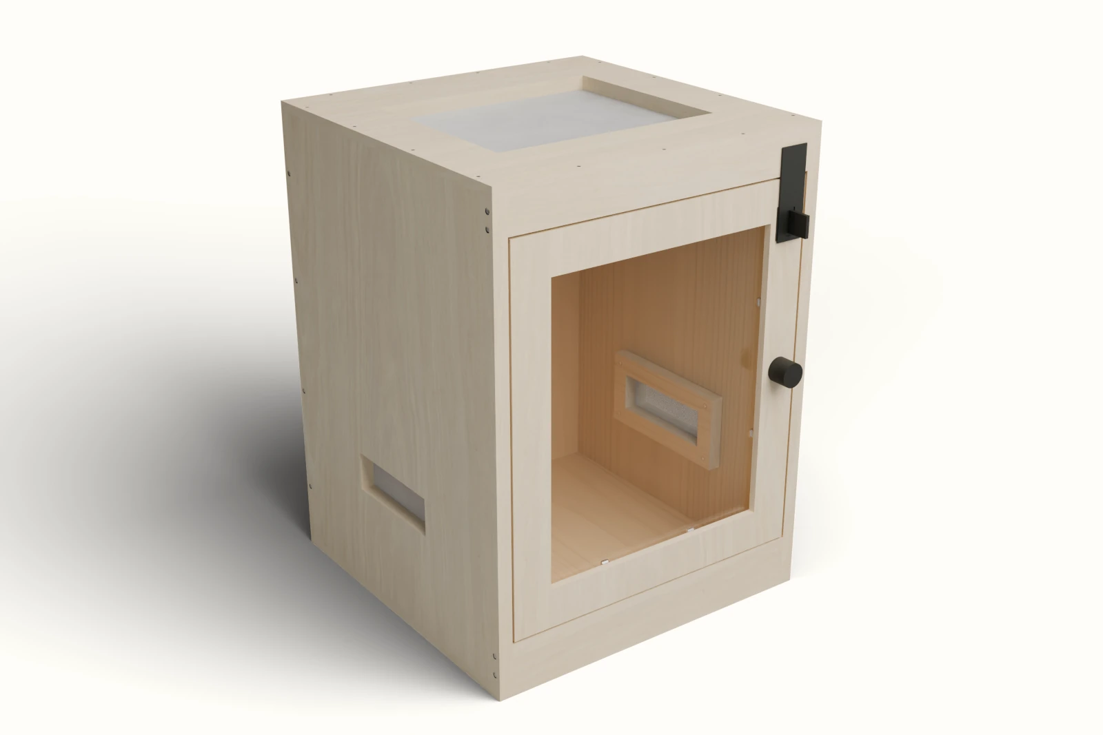
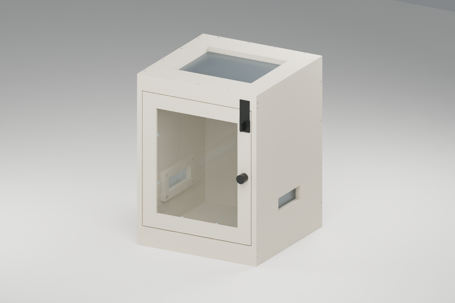
Finish preview: veneer covers the wooden exterior, roof and exposed edges. This full wrap needs revised veneer quantities, core cuts and door clearances before construction; it is not included in this guide’s cut list. Natural grain and color vary by sheet.
About these previews
Rendered from this enclosure’s own construction model, using maple, white oak or walnut textures on the exterior surfaces. Added veneer and edge-band thickness is not modeled here. Construction steps, dimensions, shopping quantities, PDF and 3D reference remain the reviewed guide. Confirm the selected veneer, adhesive, balanced panel treatment and hardware clearances in a coordinated construction revision before building the full wrap.
Texture scans by Jenelle van Heerden via Poly Haven: Maple, White oak, Walnut. CC0 texture license. The scans illustrate natural wood and are not samples from the veneer supplier’s current batch.
A picture-led guide to checking the parts, building the box and fitting the door and screens. Each numbered operation has a picture, a short action list and a check before moving on.
Construction: v5-candidate-01 · Guide: clear-guide-02 · 3 October 2026
Published 3 October 2026. Read the receiving checks before cutting and the installation holds before use.
Follow the build in 3D
Complete enclosure
More model controls
Select a visible part for its name and ID.
About the model
Temporary clamps and supports appear in the step pictures, not in this 3D view. Early machining stages are previews of the finished part, not a simulation of a cutter. Purchased fittings are simplified envelopes. Open-door movement is an illustrative pose, not the concealed hinge’s exact path. Hiding the roof is a viewing aid; the real roof is glued in place.
This is an intermediate woodworking project. You need controlled saw cuts, guided routing, stopped drilling and careful hinge fitting. Clearer instructions make the work easier to follow; they do not remove the need for those skills.
Width is left-to-right while facing the open front. The clear shell does not subtract local hinges, the lower front strip or screen frames. Knob/hasp and rear restraint project beyond the body. The planning space includes access, not a verified heat clearance.
How the box goes together
The plywood walls sit in shallow edge recesses in the bottom and roof. Glue and screws join them, and the full back helps keep the box square. The drawings show each recess and screw position.
A rabbet is a shallow recess cut along a panel edge. Crosscut means shorten a piece; rip means make it narrower.
Scope: Indoor wooden shell only. No standing water, saturated substrate, outdoor use, stacking, casters or equipment supported by the mesh. No species suitability or load rating is established.
Find the next operation
N07 · ILLUSTRATED PLAN
Start here
Follow the numbered operations in order. Open the referenced drawing only when that operation calls for it. The workshop pages hold exact settings and buying details so they do not crowd each practical step.
Use a flat, stable bench with room for supported sheets and a clamped case. Keep a separate clean space for the door, pane, hardware and curing parts. Arrange a helper for loose-wall assembly, turning the clamped box and handling the door.
Have ready
What it is for
Tape/rule, square, straightedge and caliper
Check stock, set finished sizes and record thickness. A caliper measures thickness accurately.
Supported saw, suitable blades and guides
Break sheets into blanks and finish straight, square edges. Use carriers/push devices for narrow stock.
Guided router, straight cutter, template and chisel
Make shallow case joints, vent openings and the pane recess. Keep the work and waste supported.
Stopped drill/drill press or verified hinge jig
Control hole position and depth. A depth stop prevents drilling through a thin face.
35 mm hinge bit; 11/64 in clearance bit; 3/16 in knob bit
These are specific operations, not a universal drill set. Use metric hinge tooling directly.
Pilot bits, starting trials at 7/64 in for #8 and 3/32 in for #6
Confirm with the real screw root, material and depth before drilling finished parts.
Four 24 in clamps, two 30 in clamps; at least 4 in throat
Rehearse actual bar, pad and driver clearances. Use protective wood strips and stable supports.
Hand driver, brush, sanding supplies and dust extraction
Controlled screw seating, glue cleanup and finish preparation.
Acrylic-compatible cutting tools; mesh snips and handling gloves
Use OPTIX guidance and protect the cut wire edges. No gloves near rotating cutters.
PPE, ventilation and lighting directed by tools/products
Read their manuals and labels. Protect eyes, hearing and breathing as the operation requires.
Time: Active cutting and assembly time depends on skill and equipment. Plan separate offcut trials, stock stabilization, two glue stages and coating cure. Do not schedule occupancy from an invented weekend estimate.
Shopping list
N07 · ILLUSTRATED PLAN
Get ready
Shopping list
Exact models are kept with the guide. A replacement product can change holes, clearances, exposure limits or capacity. Verify delivered parts before cutting.
Plywood sheets PLY
Birch sanded plywood project panel · 128220
3 plywood sheets.
Nominal 2 × 4 ft project panels. Each must provide the minimum 23½ × 47½ in before trimming. The layouts produce all fourteen wooden pieces.
No complete, current location-qualified price quote is supplied. Check delivery size, taxes, stock condition and pack changes. Unused pack contents are not installed hardware.
N07 · ILLUSTRATED PLAN
Get ready
Shopping list · continued
Exact models are kept with the guide. A replacement product can change holes, clearances, exposure limits or capacity. Verify delivered parts before cutting.
Restraint kit V5H06
Hillman Simple Mount furniture anti-tip kit · 9976524
1 restraint kit.
HOLD: the attachment to this exact plywood still needs manufacturer confirmation. Buying the kit does not resolve that connection.
No complete, current location-qualified price quote is supplied. Check delivery size, taxes, stock condition and pack changes. Unused pack contents are not installed hardware.
N07 · ILLUSTRATED PLAN
Get ready
Shopping list · continued
Exact models are kept with the guide. A replacement product can change holes, clearances, exposure limits or capacity. Verify delivered parts before cutting.
Hinge screws HINGE-SCREWS
Blum deep-thread wood fixing screw · 606N-100
1 box of 100 screws.
Use eight, reserve two as requested spares and keep the other 90 as surplus. Loose supplier quantities may reduce waste only for the same 606N screw.
Abrasives, applicators, cleanup cloths and masking depend on the stock and work. Price them separately.
No complete, current location-qualified price quote is supplied. Check delivery size, taxes, stock condition and pack changes. Unused pack contents are not installed hardware.
N07 · ILLUSTRATED PLAN
Get ready
Shopping list · continued
Exact models are kept with the guide. A replacement product can change holes, clearances, exposure limits or capacity. Verify delivered parts before cutting.
Trial offcuts COUPONS
Labeled plywood/finish/hardware trial coupons · offcuts from PLY sheets
Reserve sound layout offcuts.
Keep plywood and acrylic pieces for the joint, hardware and coating trials. No extra sheet is assumed.
Optional equipment EQUIPMENT
Separately selected lighting/heating and cable protection · unselected
Not included in this shell plan.
Select lighting, heating, cable protection and their supports separately for the intended use.
No complete, current location-qualified price quote is supplied. Check delivery size, taxes, stock condition and pack changes. Unused pack contents are not installed hardware.
Cut list
N07 · ILLUSTRATED PLAN
Prepare the parts
Cut list
Quantity: one of each ID. Sizes below follow each part’s first and second drawing directions, u and v. Use the exact values for fabrication. A rough blank is larger; the saw cut is allowed between blanks, not subtracted from the finished part.
Plywood: matched veneer-core cabinet stock; 0.720 in reference thickness. Acrylic: selected 0.220 in OPTIX. Mesh: selected 304 stainless, 20 × 20, 0.032 in overall. Do not interchange these materials.
General panel length/width tolerance: ±1/64 in (±0.397 mm). Door: ±0.010 in (±0.254 mm). Matched walls: within 0.010 in. Joint depth: ±0.005 in (±0.127 mm). These are this plan’s shop targets, not universal woodworking standards.
N07 · ILLUSTRATED PLAN
Prepare the parts
Cut list · continued
Quantity: one of each ID. Sizes below follow each part’s first and second drawing directions, u and v. Use the exact values for fabrication. A rough blank is larger; the saw cut is allowed between blanks, not subtracted from the finished part.
Plywood: matched veneer-core cabinet stock; 0.720 in reference thickness. Acrylic: selected 0.220 in OPTIX. Mesh: selected 304 stainless, 20 × 20, 0.032 in overall. Do not interchange these materials.
General panel length/width tolerance: ±1/64 in (±0.397 mm). Door: ±0.010 in (±0.254 mm). Matched walls: within 0.010 in. Joint depth: ±0.005 in (±0.127 mm). These are this plan’s shop targets, not universal woodworking standards.
Cutting diagrams
N07 · ILLUSTRATED PLAN
Prepare the parts
Cutting layout · PLY-1
Keep the grain arrow and the labeled offcuts. The rectangles are rough blanks. Measure your actual sheet and saw kerf first; defects can invalidate this arrangement.
For plywood, square the long edge and adjacent end, separate the large-part block from the narrow side strip, then cut the large blanks and supported small pieces. Keep the full layout nearby; do not discard a strip before checking its parts.
N07 · ILLUSTRATED PLAN
Prepare the parts
Cutting layout · PLY-2
Keep the grain arrow and the labeled offcuts. The rectangles are rough blanks. Measure your actual sheet and saw kerf first; defects can invalidate this arrangement.
For plywood, square the long edge and adjacent end, separate the large-part block from the narrow side strip, then cut the large blanks and supported small pieces. Keep the full layout nearby; do not discard a strip before checking its parts.
N07 · ILLUSTRATED PLAN
Prepare the parts
Cutting layout · PLY-3
Keep the grain arrow and the labeled offcuts. The rectangles are rough blanks. Measure your actual sheet and saw kerf first; defects can invalidate this arrangement.
For plywood, square the long edge and adjacent end, separate the large-part block from the narrow side strip, then cut the large blanks and supported small pieces. Keep the full layout nearby; do not discard a strip before checking its parts.
N07 · ILLUSTRATED PLAN
Prepare the parts
Cutting layout · ACRYLIC-1
Keep the grain arrow and the labeled offcuts. The rectangles are rough blanks. Measure your actual sheet and saw kerf first; defects can invalidate this arrangement.
Support acrylic fully and retain its masking while cutting. For mesh, protect all wire ends during handling. These layouts establish a feasible purchase quantity; they do not claim an optimum.
N07 · ILLUSTRATED PLAN
Prepare the parts
Cutting layout · MESH-1
Keep the grain arrow and the labeled offcuts. The rectangles are rough blanks. Measure your actual sheet and saw kerf first; defects can invalidate this arrangement.
Support acrylic fully and retain its masking while cutting. For mesh, protect all wire ends during handling. These layouts establish a feasible purchase quantity; they do not claim an optimum.
N07 · ILLUSTRATED PLAN
Get ready · 1 OF 33
1. Check the plywood before cutting
Parts: All wooden pieces
Have ready: Caliper, straightedge, square, pencil and a flat place to store the sheets.
Before you start: These cuts use 0.720 in (18.288 mm) plywood. That is a design input, not a measurement of your wood. Stop if your batch differs.
Construction illustration. Not to scale.
Lay the three sheets flat on full support. Choose the outward-facing surface of each and mark the direction of the visible grain.
Measure each sheet at several sound edges. It must provide at least 23½ × 47½ in (596.9 × 1206.5 mm) before the edge trimming shown in the layouts.
Reject bowed sheets, separated layers or missing core wood where joints, hinges or screws will go. Use one matched batch of veneer-core cabinet plywood. Do not substitute MDF, particleboard or treated wood.
Write the measurements on the receiving sheet. If thickness, usable size or kerf differs, have the coordinated cut list, drawings and model regenerated before cutting. Do not plane away the face veneer.
Check before continuing: The batch measurements match the plan and the sound cutting areas are marked.
Watch out: Buying by the “¾ inch” label alone.
Allow time: Let the wood settle in the intended indoor workspace. Stable measurements and condition matter more than a fixed number of hours.
The use and installation limits on the Before you build page also apply. This is an indoor wooden shell, not a tank or a stacked enclosure.
Have ready: The shopping list, delivered products, their instructions, caliper and labeled bags.
Before you start: Buy the exact hinge and separate mounting plate. A similar-looking fitting can need different holes.
Construction illustration. Not to scale.
Match every model number to the shopping list. Keep the two Blum hinges, two mounting plates and eight hinge screws together.
Check the delivered latch hole pattern, eight glazing clips and their screws, knob screw and restraint kit. Check screw lengths and head shapes before any drilling.
Keep the supplier instructions with each group. The clips need a trial to establish their fixing holes; the knob screw must engage without bottoming out.
The restraint-to-plywood connection still needs manufacturer confirmation. Resolve that connection and the intended support location before treating the enclosure as ready to install.
Check before continuing: Every fitting is identified and incompatible or unconfirmed items are set aside.
Watch out: Assuming the plate comes with the hinge.
The latch is the positive closure. Soft-close hinges do not replace it.
Have ready: Sound plywood offcuts, the real hinges/plates/clips, acrylic offcut, router, stopped drill and coating supplies.
Before you start: Do not machine the finished door until these trials work. Use the same thickness and tools as the real parts.
Construction illustration. Not to scale.
Make a shallow edge recess on an offcut. Fit another piece of the same plywood into it. It should seat without hammering or a loose gap.
Reproduce the hinge cup, mounting plate and their pilots using the hinge detail. Check that the screws seat without splitting, stripping or coming through the far face.
Make a small pane recess and try a real clip with acrylic. Prepare and fully cure a separate coated sample, then check that the pane lies flat and the clip holds it gently.
Record the accepted settings, photograph the trials and keep the samples. A failed trial means stop and correct the setup, not force the finished part to fit.
Check before continuing: Bare-wood joints and the complete cured hardware stack both fit.
Watch out: Skipping the coated trial because the bare wood fits.
Allow time: The finish sample needs full cure before its fit can be accepted. Use the coating schedule later in this guide.
A trial piece is also called a coupon. It checks fit and workmanship; it does not prove load capacity or animal suitability.
Have ready: Supported sheet saw or table saw, suitable blade, guides, square, push devices and offcut support.
Before you start: Follow your saw’s instructions. Secure the sheet and offcuts; do not cut narrow pieces freehand. Do not wear handling gloves near rotating machinery.
Construction illustration. Not to scale.
Read all three plywood layouts before cutting. Measure the blade’s actual cut width on scrap. The layouts allow a ⅛ in (3.175 mm) saw cut and a ⅛ in trim at each sheet edge.
Square one long edge and the adjacent end. Separate the main block from the marked narrow side strip, then crosscut the large blanks in the shown order.
Cut the smaller pieces from the side strips with safe support or a carrier. Keep the grain direction shown. Reserve sound scraps for trials.
Leave each rough blank ⅛ in (3.175 mm) larger overall in each long direction than its finished size. Do not subtract the saw cut from a required part size.
Check before continuing: All fourteen plywood blanks are present, with their rough sizes and grain direction intact.
Watch out: Treating an offcut as waste before checking the small-part layout.
The layouts prove a workable fit, not the cheapest possible arrangement. Larger saw cuts, defects or undersize sheets require a revised layout.
Have ready: The finished cut list, square, fine-rule measuring tool, caliper, pencil and removable tape.
Before you start: A readable fraction marked “about” is an aid only. Use the exact setting value for the final cut.
Construction illustration. Not to scale.
Bring each blank to the finished dimensions in the cut list. Check opposite edges for parallel cuts and the corners with a square. Keep the door flat.
Make the left and right walls as a matched pair. Their corresponding dimensions must differ by no more than 0.010 in (0.254 mm).
Label every piece with its plain name and ID. Mark OUTSIDE A, INSIDE B and FRONT where applicable. Mark the two measuring edges shown on its drawing.
Keep the labels visible when flipping a panel. In a drawing, u means the first measuring direction and v means the second; neither always means enclosure width or height.
Check before continuing: Each piece has the correct size, thickness, grain direction and measuring-edge marks.
Watch out: Mirroring the left wall just because its outside face is turned over.
The shallow plywood joints need accurate routing. Use the joint drawings and the accepted trial pieces.
Parts: Bottom P01 · Roof P02 · Left wall P03L · Right wall P03R
Have ready: Guided router, suitable straight cutter, depth gauge, clamps, support board and the accepted trial piece.
Before you start: Clamp the work to a full support board. Keep the glue-contact faces square and bare. Stop if routing exposes a void at a joint or screw location.
Inside faces and the three recessed bottom edges. A shallow recess along an edge is called a rabbet.
Put the bottom inside face up. Cut the recesses along its left, right and back edges. Cut the matching roof recesses on its inside face, which faces down when assembled.
Set the recess depth to ¼ in (6.35 mm). Set its width to the measured mating plywood, with 0 to 0.005 in (0 to 0.127 mm) extra for fit. Prove both settings on scrap first.
Cut the rear-edge recess on the inside face of each wall. Keep the FRONT labels visible so the recess goes at the rear.
Use controlled passes and your router’s specified feed direction. Clear the overlapping rear corners fully so the back can seat; leave the bearing surfaces flat.
Check before continuing: The panels seat by hand. Bottom and roof retain 0.47 in (11.94 mm) of wood beneath each recess.
Watch out: Routing the outside face or leaving a lump at a rear corner.
Parts: Roof P02 · Left wall P03L · Right wall P03R
Have ready: Part drawings, square, drill, saw, guided router or sharp chisel and a support board.
Before you start: Support and restrain the waste piece before finishing the cut. It must not drop into the blade or pull out a veneer.
Construction illustration. Not to scale.
Mark each opening from the finished measuring edges shown on the part drawing. Both wall openings are low in the case; the roof opening belongs in the roof.
Drill a starter hole inside the waste, saw near the line, then finish to the exact line with a guided cutter or chisel.
Check the corners and remove rough fibers. Keep any eased wall-opening corners inside the stated rectangular boundary. Do not enlarge an opening to hide a poor cut.
Check before continuing: Both side openings match each other, and every opening matches its drawing.
Watch out: Measuring from a rough edge or cutting the roof opening in the bottom.
Parts: Complete enclosure / parts identified in the picture
Have ready: Part drawings, stopped drill, 11/64 in bit, countersink, square and sacrificial support.
Before you start: Check the entry face on the drilling sheet. A pass-through hole and a smaller screw-gripping pilot do different jobs.
Construction illustration. Not to scale.
At the stations marked C, drill the 11/64 in (4.3656 mm) clearance holes through the outer piece. Support the exit face to reduce tear-out.
Use the actual screw head to set the countersink. The head must finish flush without crushing the face veneer.
Leave the receiver pilots for the clamped dry fit. Those smaller holes must line up through the assembled joint; do not guess their position from the opposite face.
Check before continuing: Every C hole is present, at the correct face and location, with an undamaged head seat.
Watch out: Drilling all holes the same diameter or boring pilots freehand into thin edges.
A clearance hole lets the screw pass through the first piece. A pilot guides its threads into the receiving piece.
Have ready: Door drawing, square, guided router/template, chisel and flat sacrificial support.
Before you start: Use the accepted pane-and-clip trial. Lay the door INSIDE B face up and preserve the hinge-edge label while flipping it.
Construction illustration. Not to scale.
Check the door blank against the exact cut list. Mark its viewing window and the wider recess around it from the door drawing; the wood border is 2 in (50.8 mm).
Cut the viewing opening through the door. From the inside, cut the wider recess to 0.345 in (8.76 mm). That depth combines this pane’s thickness and the selected clip offset.
Square the recess corners with a chisel. Ease the exposed viewing edges lightly without reducing the lip supporting the pane. Keep the outer door edges accurate.
Check before continuing: The recess is flat and its corners will not trap the pane. The door stays flat.
Watch out: Routing the outside face or gluing the pane into its recess.
The wider, shallow area around the opening is the glazing rebate. It supports the clear pane while clips keep the pane removable.
Have ready: Verified Blum boring jig or controlled drill-press setup, 35 mm bit, depth stop and accepted offcut.
Before you start: Stop if the stock, jig, drill point or real hinge differs from the trial. Bore from the inside face only.
Construction illustration. Not to scale.
Place each cup center 21.5 mm from the hinge edge. Place the lower and upper centers 1 3/16 in (30.1625 mm) from their respective door ends.
Bore the 35 mm cups 13 mm deep. Use those metric hardware sizes directly, not an approximate fractional bit or a ½ inch depth.
For the screw-on hinges, mark the 45 mm fixing pitch with the fixing line 9.5 mm farther inward from the cup center. Use the accepted stopped #6 screw pilot trial; 3/32 in is only the starting trial size.
Check the thin wood beside the pane recess and around the cup flange. Reject splitting, torn veneers or a loose fixing instead of using a larger screw.
Check before continuing: Both cups seat fully. Nominal front wood below a cup is 0.20819 in (5.29 mm).
Watch out: Drilling the 8 mm fixing holes shown for a different, press-in hinge.
Parts: Clear pane G01 · Left screen M01L · Right screen M01R · Roof screen M02
Have ready: The acrylic/mesh layouts, acrylic-compatible cutting tools, snips and mesh handling gloves.
Before you start: Cut mesh edges are sharp. Keep them covered during handling. Use gloves for handling mesh, not near rotating cutters.
Construction illustration. Not to scale.
Leave the acrylic’s masking in place. Support it and cut at room temperature using the OPTIX fabrication method and the exact pane size in the cut list.
Smooth the acrylic edges and ease sharp corners without reducing the listed support overlap. Do not force a saw intended for another material through it.
Cut two side screens and one roof screen from the mesh layout. Flatten gently without breaking or sharply kinking wires. Keep all sharp ends contained.
Check before continuing: All eighteen fabricated pieces are now present. The pane is flat and the three screens match their listed sizes.
Watch out: Using a thicker replacement pane without rechecking the recess and clips.
Parts: Bottom P01 · Left wall P03L · Right wall P03R · Back P04 · Lower front strip P05 · Upper front strip P06 · Roof P02
Have ready: Same bench setup and helper. Keep all six padded clamps within reach.
Before you start: Keep the walls supported. The separated picture shows where parts go; the pieces must touch in the dry fit.
Added pieces are orange and separated for visibility. Move them into contact before clamping.
Lower the back into the recesses at the rear of the walls and bottom. Check that it reaches the bottom all the way across.
Place the taller front strip between the walls, on top of the bottom. Line up its front face with the wall fronts.
Have your helper hold the shorter front strip at the top. Fit the roof over the walls and back, with its recesses facing down. The upper strip sits directly beneath the roof.
Check before continuing: All seven pieces are present. The back is seated and the roof is fully down.
Watch out: Lifting the loose box by its roof.
Trying the pieces together without glue is called a dry fit. It catches a backwards panel or a poor joint while you can still correct it.
Parts: Bottom P01 · Left wall P03L · Right wall P03R · Back P04 · Lower front strip P05 · Upper front strip P06 · Roof P02
Have ready: Four 24 in clamps, two 30 in clamps, padded wood strips, square and fine-rule measuring tool. Each clamp needs at least 4 in reach from bar to pad.
Before you start: Keep your helper steadying the box while you fit the clamps. Keep the support blocks clear of the lower jaws.
Six clamps in total. Two rear clamps are partly hidden. Generic clamp shapes; rehearse with your own.
Fit four clamps across the width: low and high at both front and back. Add two from bottom to roof, one near each side. Pad every jaw.
Tighten only enough to close the joints. Keep pads on solid wood, clear of vents and screw holes. Stop if a panel bends or a joint will not seat.
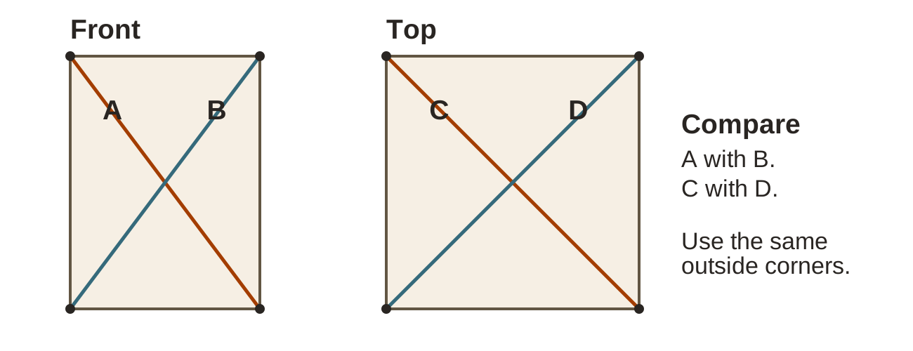
Compare the two corner-to-corner measurements on the front, then the two on the top. Each pair must differ by no more than 1/32 in (0.79 mm). Check the corners with a square too.
Check the uncoated outside size: 18 × 18 × 24 in (457.2 × 457.2 × 609.6 mm). Check the front opening: 16.56 in (420.62 mm) wide and 19.06 in (484.12 mm) high.
Check before continuing: All joints close, the opening matches, and the bottom does not rock. Record both pairs of diagonals.
Watch out: Pulling a warped panel straight by overtightening.
The box is still unglued. Keep it clamped and supported for the next operation.
Parts: Bottom P01 · Left wall P03L · Right wall P03R · Back P04 · Lower front strip P05 · Upper front strip P06 · Roof P02
Have ready: Helper, stable padded supports, stopped drill, accepted pilot bit, screw-location drawings and hand driver.
Before you start: Keep the box fully clamped while your helper turns it onto its back. Do not lift by the roof. Reposition one clamp at a time only when the others keep the joints seated.
Construction illustration. Not to scale.
Place the clamped box on stable padded supports under its back. The open front now faces up. Keep clamp bars, jaws and drill paths clear of the bench.
Drill the smaller receiving holes through the existing clearance holes. Start the #8 screw trial at 7/64 in (2.7781 mm), then use the accepted size for the real screw root and this plywood. Set a depth stop to avoid breaking through.
Check each edge-entry and face-entry location on the drilling drawings. Test-fit the shell screws by hand; the head must seat without splitting, stripping or an exposed point.
Temporarily position the screen frames and roof strips at their drawings’ stations, using mesh offcuts to reproduce the 0.032 in (0.8128 mm) layer. Transfer and drill their stopped receiver pilots. Remove the trial pieces afterward.
Mark the matching joints, then carefully take the box apart with your helper. Keep all labels and accepted drill settings.
Check before continuing: All 46 shell and 18 screen-retainer stations align, with sound receiving wood and safe screw tips.
Watch out: Drilling receiver pilots while the joint is loose or forgetting the mesh layer.
A pilot is the smaller hole that guides the screw’s threads. This guide does not assign a load rating to the screw pattern.
Parts: Bottom P01 · Left wall P03L · Right wall P03R · Back P04 · Lower front strip P05 · Upper front strip P06 · Roof P02
Have ready: Titebond III, brush, damp cleanup cloth, helper, rehearsed clamps and #8 × 1¾ in shell screws.
Before you start: Rehearse first. Titebond III has a limited working time; do not begin a glue-up you cannot seat and clamp in time. Leave the roof and upper front strip unglued in this stage.
Construction illustration. Not to scale.
Use the same supported position and clamp sequence you rehearsed. Apply glue only to the bare-wood joints of the bottom, walls, back and lower front strip.
Seat those parts and put the roof on dry to hold the spacing. Close the clamps lightly and repeat the opening, diagonal and flush-face checks.
Drive the matching lower-joint screws by hand or with controlled torque. Keep the screw heads flush without crushing the veneer. Wipe fresh squeeze-out without soaking the plywood.
Check before continuing: The lower joints are seated and square. The roof remains removable because it has no glue yet.
Watch out: Gluing every joint at once before rehearsing the sequence.
Allow time: Follow the delivered glue label. Plan an overnight, at least 24-hour undisturbed wait before stressing this new assembly or removing the dry roof for the next glue stage. This is a conservative shop sequence, not a universal clamp-time rule.
At 70°F (21°C) and 50% RH, the maker lists 8–10 minutes open time and 20–25 minutes total assembly time. Current application guidance says above 47°F (8°C). Actual conditions and the label govern.
Parts: Bottom P01 · Left wall P03L · Right wall P03R · Back P04 · Lower front strip P05 · Upper front strip P06 · Roof P02
Have ready: Same glue, helper, clamps, square, measuring tool and remaining shell screws.
Before you start: First confirm the lower assembly has set. Support the box throughout; do not pull on a newly glued joint.
Construction illustration. Not to scale.
Lift off the dry roof. Clean any stray glue from its seating surfaces and confirm the upper front strip and roof still fit.
Apply glue to the upper strip’s mating joints and the roof joints. Seat both parts, reclamp and repeat the opening and diagonal checks.
Install the remaining shell screws at their listed stations. There are 46 shell screws in the completed box. Clean squeeze-out and leave the assembly undisturbed.
After the glue has cured, inspect every seam and screw head. Remove dried glue without digging into the veneer.
Check before continuing: The roof and header are fixed, seams are closed and all 46 shell screw heads are sound.
Watch out: Leaving a glue ridge where a later fitting must sit.
Allow time: Do not stress the new joints for at least 24 hours. Follow the actual glue’s clamp and cure instructions for the temperature and joint condition.
The glued roof is permanent. Later screen maintenance happens through the open front, not by removing the roof.
Parts: Bottom P01 · Left wall P03L · Right wall P03R · Back P04 · Lower front strip P05 · Upper front strip P06 · Roof P02 · Door D01
Have ready: The exact two hinges, two plates, eight #6 × ⅝ in screws, jig, stopped drill, hand driver and helper.
Before you start: Support the door while clipping or unclipping a hinge. Follow the accepted offcut setup; do not drill a new pattern to make the wrong plate fit.
Construction illustration. Not to scale.
Transfer the mounting-plate stations from the left-wall drawing onto its inside face. The fixing line is 2.23875 in (56.86 mm) behind the raw front; each plate has a 32 mm fixing pitch.
Drill the accepted stopped pilots and fit the two plates. Fit the two screw-on hinges in the door cups. Seat screws gently by hand.
With your helper holding the door, clip both hinges onto their plates. Confirm both connections engage fully.
Adjust the bare door to an even 3 mm (about ⅛ in) gap around the opening. The hinge centers are 16.44878 in (417.8 mm) apart; check the real hinge action before proceeding.
Check before continuing: The door sits flush, moves without rubbing and remains supported by two fully engaged hinges.
Watch out: Using hinge adjustment to disguise a twisted box or incorrectly cut door.
The two hinge centers are slightly farther apart than the door is wide. Digital open-door pictures are illustrative; the real hinge trial is the motion check.
Have ready: National N305-979 hasp, seven #10 × ⅝ in screws, Liberty knob, square, stopped drill and hand driver.
Before you start: Close and support the door before marking. Keep every latch screw in full wood, clear of the pane recess. Do not force the latch to pull a misaligned door shut.
Construction illustration. Not to scale.
Place the hasp base on the upper front strip at its drawing location. Its swinging leaf reaches the swivel staple on the upper-right wood of the door.
Use the actual fitting to transfer all seven fixing holes, starting from the nominal stations shown. Confirm that the staple turns freely and the screw locations clear all recesses.
Drill stopped pilots and fit the hasp with its specified screws. Open and close it several times without forcing the door.
Drill the knob’s 3/16 in (4.7625 mm) pass-through hole at the door drawing station. Fit its supplied 8-32 × 1 in machine screw. Verify engagement without bottoming out or crushing the wood.
Check before continuing: The knob is firm and the swivel hasp closes freely with all screws seated in sound wood.
Watch out: Drilling the hasp from an approximate picture instead of the actual product.
Have ready: The eight Rockler clips and supplied screws, pane, stopped drill, helper and flat padded bench.
Before you start: Support and unclip the door. Lay its inside face up. Keep drilling swarf away from the pane and remove the pane before boring.
Construction illustration. Not to scale.
Place the pane in the recess and try all eight clips at the nominal stations shown on the glazing drawing. Keep the pane centered and flat.
Transfer each real clip’s fixing hole. The clip tip must overlap the pane by ⅛ to ¼ in (3.175–6.35 mm). Keep the fixing center at least ¼ in (6.35 mm) from both the recess edge and the outside door edge.
Remove the pane, then drill the accepted stopped pilots. Actual screw penetration must be no more than 0.60 in (15.24 mm). Refit briefly to check gentle retention, without bending the pane.
Check before continuing: All eight real clip locations meet the edge and overlap limits, and no screw can break through the front.
Watch out: Filling the pane’s expansion gap or tightening clips until the acrylic bows.
This is a measured hardware-transfer step, not “cut to fit.” The supplied clip hole offset is not fully dimensioned in the retained product evidence, so the real clip establishes the final fixing position before finishing.
Parts: Complete enclosure / parts identified in the picture
Have ready: Helper, hand driver, labels, camera and separate bags for each hardware group.
Before you start: Keep fingers clear of hinge joints. Hold the door when releasing either hinge. Never force it beyond the actual hardware’s travel.
Construction illustration. Not to scale.
Rehang the trial door and test its full available movement. Check the hasp open and closed, hand access, pinch points and hinge-release access.
Photograph and record the accepted positions. Any rubbing, splitting or poor fit must be resolved before coating.
Support and unclip the door. Remove the pane, clips, hinges, plates, knob, hasp and all screen pieces. Label the hardware bags and keep the screws with their fittings.
Check before continuing: You have the bare wooden box, bare door and six screen-retaining pieces ready to finish.
Watch out: Coating around installed hardware or leaving a known fit problem until after curing.
The model communicates the parts and sequence. It does not replace this real movement and access check.
Have ready: The coating label and safety sheet, suitable abrasives, dust extraction, soft brush and clean cloths.
Before you start: Follow the product’s ventilation, protective equipment and waste-disposal instructions. Keep occupants, water and heat equipment away from the work.
Construction illustration. Not to scale.
Remove glue residue and layout marks. Sand in the product’s stated preparation sequence, then remove dust thoroughly.
Lightly soften exposed sharp edges. Keep joint bearing faces, pane supports and door fitting edges accurate; do not round them over or sand through the face veneer.
Inspect every cut edge, vent opening, recess and screw hole. Repair damaged wood before coating; finish cannot restore a split or missing layer.
Check before continuing: The surface is clean, dry and sound, including hard-to-see cut edges.
Watch out: Rounding a fit-critical edge until the carefully checked clearance changes.
Have ready: Retained Varathane 284473 Satin Triple Thick brush-on polyurethane, suitable applicator and finish-record sheet.
Before you start: This is an indoor, non-immersion coating. It is not a tank liner or proof of animal-contact suitability. Do not put wet substrate directly against the wood.
Construction illustration. Not to scale.
Read the delivered label and technical sheet before opening. Coat exposed faces, cut edges, vent edges, recesses and accessible hole walls. Keep fittings, acrylic and mesh off the work.
Apply evenly without pools in hinge cups, corners or pilot holes. The retained technical sheet gives 9 mil wet film, 3 mil dry film and nominal 50 ft² per quart; allow for losses and the actual surface.
Record batch, temperature, humidity, application time and any recoat time. The retained baseline is a 2-hour recoat interval, 48 hours before light use and 7 days for full cure at 70°F (21°C), 50% RH.
Follow the current label’s temperature, humidity and recoat limits. Cooler or damper conditions can lengthen the wait. Gently clear a blocked pilot without enlarging it.
Check before continuing: All intended surfaces have continuous coverage without thick pockets or blocked fittings.
Watch out: Treating the stated coverage as a promise that one container will cover every loss.
Allow time: Keep parts separated and protected while they dry and cure. The 7-day baseline is full cure under stated conditions, not permission to assemble early because the surface feels dry.
Have ready: Your finish record, the coated trial piece and good inspection light.
Before you start: Dry to the touch and odor-free do not establish full cure or animal safety. Keep use approval separate.
Construction illustration. Not to scale.
Check the actual elapsed time and conditions against the delivered product instructions. Leave more time if the conditions require it.
Inspect the coated trial and all parts for tackiness, soft pockets, missed edges or contamination. Correct defects using the product’s repair instructions, then restart the relevant waiting period.
Repeat the pane-and-clip fit on the cured trial. Confirm the measured coating does not close a required gap or stop a fitting from seating.
Check before continuing: The coating has completed its documented cure and the cured fitting trial passes.
Watch out: Counting calendar days while ignoring low temperature, high humidity or pooled finish.
Allow time: No use, washing or final fit acceptance until the applicable full-cure requirement is met.
This remains a dry-shell coating specification. Intended animal contact, cleaning chemicals, humidity and equipment conditions still need their own acceptance.
Parts: Bottom P01 · Left wall P03L · Right wall P03R · Back P04 · Lower front strip P05 · Upper front strip P06 · Roof P02 · Door D01
Have ready: Labeled hinge bags, hand driver, helper and a fine-rule gap gauge.
Before you start: Protect the cured finish and support the door. Do not force a clip-on hinge or overdrive a screw into its old pilot.
Construction illustration. Not to scale.
Refit the plates and hinges in their accepted holes. Seat screws gently and check for coating chips or stripped threads.
Support the door, clip both hinges fully onto their plates and check its movement. Adjust in small amounts until the door is flush and the gaps are even.
With the planned coating, each nominal gap is about 0.11211 in (2.85 mm). Measure the real gaps; this calculation does not prove fit or escape resistance.
If both soft-close dampers prevent this light door from closing, trial the manufacturer’s BLUMOTION switching adjustment. Keep the hasp as the positive closure.
Check before continuing: The actual finished door moves freely, closes consistently and has no trapped fingers or rubbing edges.
Watch out: Using hinge adjustment to compensate for a door that was cut too large.
Support and unclip the door again for the screen work that follows. Keep it on the padded bench.
Parts: Left screen M01L · Right screen M01R · Left screen frame V01L · Right screen frame V01R
Have ready: Side meshes and one-piece frames, the listed retainer screws, hand driver, gloves for mesh and padded support.
Before you start: Work with the door removed. Support the box on its back or side so the driver reaches squarely. Keep cut wire edges covered.
Construction illustration. Not to scale.
Center a side mesh over its vent from inside the case. It overlaps the opening by ½ in (12.7 mm) on every side.
Place the matching one-piece wooden frame over it. The 0.032 in (0.8128 mm) mesh layer sits between wood and wall. Do not add a gasket or deepen a recess without rechecking the design.
Fit the #8 × 1¼ in retainer screws at the prepared stations and tighten by hand until seated. Keep all cut wire ends under the wood.
Repeat on the other side. Wipe around the protected edges and inspect for loose corners, sharp ends, broken wires and sound screw engagement.
Check before continuing: Both screens are flat, fully retained and accessible for later removal.
Watch out: Letting a screw protrude outside or trapping a sharp wire beyond the frame.
The two side frames use eight of the eighteen retainer screws. Mesh attachment is not a load rating or a universal escape-resistance claim.
Parts: Roof screen M02 · Front roof strip V02F · Back roof strip V02B · Left roof strip V02L · Right roof strip V02R
Have ready: Roof mesh, four labeled strips, remaining retainer screws, hand driver and helper.
Before you start: Support the loose screen while fitting or removing strips. Never rest a lamp or other equipment on the mesh.
Construction illustration. Not to scale.
Work through the front, with the box supported for access. Center the roof mesh below the opening, with ½ in (12.7 mm) overlap on each side.
Fit the four wooden strips in their labeled positions over the cut edges. Use the ten roof-retainer screws at the prepared stations and seat them by hand.
Rehearse service access: support the mesh, remove the strips and bring the 13 × 11 in (330.2 × 279.4 mm) screen out through the front opening. The roof itself stays fixed.
Refit and inspect the wood threads and wire edges. Stop and repair a stripped fixing before use; do not simply drive it tighter.
Check before continuing: All eighteen retainer screws are present and the screen replacement path works with your driver.
Watch out: Assuming the glued roof comes off for maintenance.
The illustration isolates the roof’s inside face to explain the layers. The real roof remains attached to the box throughout this operation.
Have ready: Cured door, clean pane, eight clips with their matched screws, hand driver and padded bench.
Before you start: Lay the supported door inside face up. Remove drilling dust and grit before setting down the pane.
Construction illustration. Not to scale.
Remove the acrylic masking and clean with the compatible OPTIX method. Place the pane flat in its recess without forcing it against an edge.
Check clearance on all four sides. The nominal uncoated edge allowance is 1/16 in (1.5875 mm) per side; coating and the actual pane must still leave room.
Refit the eight clips in the accepted holes. Tighten only enough to retain the pane gently. Do not bow the acrylic or fill its movement gap.
With a helper, lift the door upright over the padded bench and confirm that the pane remains retained. Return it flat if any clip is loose.
Check before continuing: The pane stays flat and secure while remaining removable.
Watch out: Using glue, sealant or excessive clip pressure to hide a bad fit.
Use a soft cloth and acrylic-compatible cleaner. Do not assume a glass cleaner, solvent, abrasive or disinfectant is safe for OPTIX.
Parts: Complete enclosure / parts identified in the picture
Have ready: Helper, hand driver, labeled fittings and a suitable scale.
Before you start: Never lift the enclosure by its door, knob, latch or mesh. Support the complete door whenever unclipping it.
Construction illustration. Not to scale.
Refit the knob and hasp in their trialed holes. Check machine-screw engagement and that the swivel staple turns freely.
Weigh the completed door with its pane and attached fittings. Record that measured mass and compare the real door size, mass and hinge spacing with the selected Blum planning guidance.
Rehang the supported door. Confirm both hinge clips engage, then test closure, latch access and full movement again.
Check that the pane clips and screen fixings remain accessible for replacement.
Check before continuing: The measured door mass and actual operation pass the product-specific checks.
Watch out: Treating an estimated model mass as a scale measurement.
Parts: Complete enclosure / parts identified in the picture
Have ready: Suitable support furniture, level, tape measure, helper and the restraint instructions.
Before you start: Move it empty with loose items removed. The restraint-to-plywood connection is unresolved; do not treat this candidate as installation-ready until that connection is confirmed.
Construction illustration. Not to scale.
Use a continuous, flat surface supporting the whole 18 × 18 in (457.2 × 457.2 mm) base. Level the supporting furniture. Do not put small shims directly under the enclosure or add legs, casters or another enclosure above it.
Check the complete enclosure and contents load, the furniture and the building floor separately. Average weight per square foot alone does not approve a floor.
Confirm the Hillman restraint’s attachment into this plywood with its manufacturer. If added internal framing is required, stop and revise the coordinated design. Do not invent a screw connection.
Connect the wall end only as the kit directs into verified building support. Preserve access to release the restraint for service; never carry by the cable.
Check the planned service space: 25 in wide × 41 in deep × 27 in high (635 × 1041.4 × 685.8 mm), including front, left, rear and top access. This is not a heat-source clearance.
Check before continuing: The support, confirmed restraint connection and service space are documented before use.
Watch out: Calling the shell ready because it sits level while the support or restraint remains unknown.
This is a visible release hold, not a task a builder should solve by guessing. No filled tank, stacked unit or water-holding use is covered.
Parts: Complete enclosure / parts identified in the picture
Have ready: Inspection/receiving sheets, measuring tools and the selected equipment’s installation instructions.
Before you start: The completed wooden shell alone does not establish suitability for an animal. No standing water, deep wet substrate or equipment load on the mesh is approved.
Construction illustration. Not to scale.
Record the actual size, opening, diagonals, door gaps and door mass. Inspect fixings, protected wire edges, coating and pane retention. Repeat opening, closing and replacement-access checks.
Resolve the species and life-stage requirements separately, including escape gaps, ventilation, substrate and cleaning. Fine mesh does not compensate for a gap around the door.
Provide independent equipment support, manufacturer-required heat clearances and protected cable routes separated from water. Do not cut an unreviewed hole for a cable or fitting.
Measure temperature and humidity under representative operating conditions before occupancy. Watch for condensation, wet floor seams or damaged penetrations and correct the cause.
Record what was actually checked. A digital check is not a built prototype, physical test, qualified review or publication approval.
Check before continuing: Every installation and intended-use hold is closed with evidence. Otherwise, keep the enclosure out of service.
Watch out: Treating a finished-looking shell as an approved habitat.
Parts: Complete enclosure / parts identified in the picture
Have ready: Compatible cleaners, soft cloth, hand driver, helper and inspection log.
Before you start: Remove the occupant and disconnect equipment safely before maintenance. Support the door and loose screens when releasing their fittings.
Construction illustration. Not to scale.
Before use, check the latch, hinge engagement, pane clips and all screen edges. Stop using the enclosure if a fixing is loose, the coating has failed or a wire edge is exposed.
Use cleaners verified for each material. For the hinges, follow Blum’s lightly water-dampened cloth method; do not spray the mechanism or soak the plywood.
After a moisture incident, dry, inspect and repair using the coating instructions. Do not hide softened wood, open seams or trapped moisture under a fresh coat.
Replace the pane with the door supported flat and clips removed. Replace screens through the open front. Inspect the wood threads every time a screw is removed.
Record replacements. Changing plywood, pane thickness, hinges, mesh, finish or support requires the relevant fit and use checks again.
Check before continuing: The maintenance log identifies defects, repairs and replacement parts.
Watch out: Reusing a stripped screw hole because the retainer still looks attached.
The step pictures explain what to do. These drawings locate the exact cuts and holes. Keep the named drawing beside the corresponding step. None is a full-size template; never measure a printed picture to size a part.
Mark or term
Plain meaning
A / B
A is the outward/show face; B is the inside face. An inside operation may be drawn in the same coordinate projection as an outside view. Keep physical edge labels when flipping.
u0 / v0
The two finished measuring edges. Begin each location from these edges, not from the previous hole.
+u / +v
Directions measured across the part. The mapping to enclosure X/Y/Z appears beneath each drawing.
X / Y / Z
X goes right, Y goes toward the back, Z goes up, facing the access front.
Entry X+, X−, Y+, Y−, Z+, Z−
The drill travels in that direction from its listed starting face. For example, a bottom Z+ hole enters upward from below.
C / P
C is a clearance hole through the first piece. P is the smaller receiving pilot, accepted on a trial and transferred during the clamped fit.
Blue dashed shape / white opening
Blue locates a shallow recess; white is a cut completely through the part. Read its depth and entry face.
Field transfer
Use the delivered fitting at the stated checkpoint to locate its actual holes. Keep the stated margins, overlap and penetration limits.
Grain arrow
Keep the intended face-grain direction when nesting and labeling the parts.
Drawing versus schedule
The diagram labels can be abbreviated. The exact machining schedule on the following reference pages retains the source values.
Do not mirror the hinge side because a panel is turned over. Mark its original FRONT, BOTTOM and INSIDE face before any machining. If you cannot reconcile an entry direction with the joint section, stop before drilling.
Workshop drawing · Overall
N07 · ILLUSTRATED PLAN
Workshop reference
Source construction revision v5-candidate-01. Dimensions govern. Hardware envelopes and clamp shapes are explanatory, not manufacturer CAD or physical tests.
Workshop drawing · Exploded Assembly
N07 · ILLUSTRATED PLAN
Workshop reference
Source construction revision v5-candidate-01. Dimensions govern. Hardware envelopes and clamp shapes are explanatory, not manufacturer CAD or physical tests.
Workshop drawing · Joints
N07 · ILLUSTRATED PLAN
Workshop reference
Source construction revision v5-candidate-01. Dimensions govern. Hardware envelopes and clamp shapes are explanatory, not manufacturer CAD or physical tests.
Workshop drawing · Hinge Detail
N07 · ILLUSTRATED PLAN
Workshop reference
Source construction revision v5-candidate-01. Dimensions govern. Hardware envelopes and clamp shapes are explanatory, not manufacturer CAD or physical tests.
Workshop drawing · Glazing Section
N07 · ILLUSTRATED PLAN
Workshop reference
Source construction revision v5-candidate-01. Dimensions govern. Hardware envelopes and clamp shapes are explanatory, not manufacturer CAD or physical tests.
Workshop drawing · Vent Section
N07 · ILLUSTRATED PLAN
Workshop reference
Source construction revision v5-candidate-01. Dimensions govern. Hardware envelopes and clamp shapes are explanatory, not manufacturer CAD or physical tests.
Workshop drawing · Clamp Rehearsal
N07 · ILLUSTRATED PLAN
Workshop reference
Source construction revision v5-candidate-01. Dimensions govern. Hardware envelopes and clamp shapes are explanatory, not manufacturer CAD or physical tests.
All values in this table are inches, derived from the canonical schedule. Do not round these positions to the nearest fraction. Verify depth and entry face on the part drawing. Receiver pilots require the real screw/material trial.
Part / hole
u from u0
v from v0
Entry
Diameter
Depth
Operation
P01 F001C
0.36
1.5
Z+
0.17188
0.47
clearance + countersink
P01 F002C
0.36
6.5
Z+
0.17188
0.47
clearance + countersink
P01 F003C
0.36
11.5
Z+
0.17188
0.47
clearance + countersink
P01 F004C
0.36
16
Z+
0.17188
0.47
clearance + countersink
P01 F005C
17.64
1.5
Z+
0.17188
0.47
clearance + countersink
P01 F006C
17.64
6.5
Z+
0.17188
0.47
clearance + countersink
P01 F007C
17.64
11.5
Z+
0.17188
0.47
clearance + countersink
P01 F008C
17.64
16
Z+
0.17188
0.47
clearance + countersink
P01 F009C
2.5
17.64
Z+
0.17188
0.47
clearance + countersink
P01 F010C
7
17.64
Z+
0.17188
0.47
clearance + countersink
P01 F011C
11
17.64
Z+
0.17188
0.47
clearance + countersink
P01 F012C
15.5
17.64
Z+
0.17188
0.47
clearance + countersink
P01 F013C
4.5
0.36
Z+
0.17188
0.72
clearance + countersink
P01 F014C
9
0.36
Z+
0.17188
0.72
clearance + countersink
P01 F015C
13.5
0.36
Z+
0.17188
0.72
clearance + countersink
P02 F016C
0.36
1.5
Z-
0.17188
0.47
clearance + countersink
P02 F017C
0.36
6.5
Z-
0.17188
0.47
clearance + countersink
35 mm and 13 mm hinge cup dimensions remain manufacturer metric settings. Nominal pilots listed here are trial starting values; the accepted settings must be recorded before drilling.
Exact drilling schedule · continued
N07 · ILLUSTRATED PLAN
Workshop reference
All values in this table are inches, derived from the canonical schedule. Do not round these positions to the nearest fraction. Verify depth and entry face on the part drawing. Receiver pilots require the real screw/material trial.
Part / hole
u from u0
v from v0
Entry
Diameter
Depth
Operation
P02 F018C
0.36
11.5
Z-
0.17188
0.47
clearance + countersink
P02 F019C
0.36
16
Z-
0.17188
0.47
clearance + countersink
P02 F020C
17.64
1.5
Z-
0.17188
0.47
clearance + countersink
P02 F021C
17.64
6.5
Z-
0.17188
0.47
clearance + countersink
P02 F022C
17.64
11.5
Z-
0.17188
0.47
clearance + countersink
P02 F023C
17.64
16
Z-
0.17188
0.47
clearance + countersink
P02 F024C
2.5
17.64
Z-
0.17188
0.47
clearance + countersink
P02 F025C
7
17.64
Z-
0.17188
0.47
clearance + countersink
P02 F026C
11
17.64
Z-
0.17188
0.47
clearance + countersink
P02 F027C
15.5
17.64
Z-
0.17188
0.47
clearance + countersink
P02 F028C
4.5
0.36
Z-
0.17188
0.72
clearance + countersink
P02 F029C
9
0.36
Z-
0.17188
0.72
clearance + countersink
P02 F030C
13.5
0.36
Z-
0.17188
0.72
clearance + countersink
P02 R009P
2.5
3.5
Z+
0.10938
0.498
trial pilot; coupon gate
P02 R010P
9
3.5
Z+
0.10938
0.498
trial pilot; coupon gate
P02 R011P
15.5
3.5
Z+
0.10938
0.498
trial pilot; coupon gate
P02 R012P
2.5
14.5
Z+
0.10938
0.498
trial pilot; coupon gate
35 mm and 13 mm hinge cup dimensions remain manufacturer metric settings. Nominal pilots listed here are trial starting values; the accepted settings must be recorded before drilling.
Exact drilling schedule · continued
N07 · ILLUSTRATED PLAN
Workshop reference
All values in this table are inches, derived from the canonical schedule. Do not round these positions to the nearest fraction. Verify depth and entry face on the part drawing. Receiver pilots require the real screw/material trial.
Part / hole
u from u0
v from v0
Entry
Diameter
Depth
Operation
P02 R013P
9
14.5
Z+
0.10938
0.498
trial pilot; coupon gate
P02 R014P
15.5
14.5
Z+
0.10938
0.498
trial pilot; coupon gate
P02 R015P
2.5
6
Z+
0.10938
0.498
trial pilot; coupon gate
P02 R016P
2.5
12
Z+
0.10938
0.498
trial pilot; coupon gate
P02 R017P
15.5
6
Z+
0.10938
0.498
trial pilot; coupon gate
P02 R018P
15.5
12
Z+
0.10938
0.498
trial pilot; coupon gate
P03L HP10
2.23875
2.92569
X-
0.09375
0.6
coupon_pilot
P03L HP11
2.23875
4.18553
X-
0.09375
0.6
coupon_pilot
P03L HP20
2.23875
19.37447
X-
0.09375
0.6
coupon_pilot
P03L HP21
2.23875
20.63431
X-
0.09375
0.6
coupon_pilot
P03L F001P
1.5
0
Z+
0.10938
1.28
trial pilot; coupon gate
P03L F002P
6.5
0
Z+
0.10938
1.28
trial pilot; coupon gate
P03L F003P
11.5
0
Z+
0.10938
1.28
trial pilot; coupon gate
P03L F004P
16
0
Z+
0.10938
1.28
trial pilot; coupon gate
P03L F016P
1.5
23.06
Z-
0.10938
1.28
trial pilot; coupon gate
P03L F017P
6.5
23.06
Z-
0.10938
1.28
trial pilot; coupon gate
P03L F018P
11.5
23.06
Z-
0.10938
1.28
trial pilot; coupon gate
35 mm and 13 mm hinge cup dimensions remain manufacturer metric settings. Nominal pilots listed here are trial starting values; the accepted settings must be recorded before drilling.
Exact drilling schedule · continued
N07 · ILLUSTRATED PLAN
Workshop reference
All values in this table are inches, derived from the canonical schedule. Do not round these positions to the nearest fraction. Verify depth and entry face on the part drawing. Receiver pilots require the real screw/material trial.
Part / hole
u from u0
v from v0
Entry
Diameter
Depth
Operation
P03L F019P
16
23.06
Z-
0.10938
1.28
trial pilot; coupon gate
P03L F031C
17.64
3.03
X+
0.17188
0.47
clearance + countersink
P03L F032C
17.64
8.53
X+
0.17188
0.47
clearance + countersink
P03L F033C
17.64
14.53
X+
0.17188
0.47
clearance + countersink
P03L F034C
17.64
20.03
X+
0.17188
0.47
clearance + countersink
P03L F035C
0.36
0.75
X+
0.17188
0.72
clearance + countersink
P03L F036C
0.36
1.75
X+
0.17188
0.72
clearance + countersink
P03L F037C
0.36
21.685
X+
0.17188
0.72
clearance + countersink
P03L F038C
0.36
22.435
X+
0.17188
0.72
clearance + countersink
P03L R001P
5.5
4.75
X-
0.10938
0.498
trial pilot; coupon gate
P03L R002P
5.5
7.75
X-
0.10938
0.498
trial pilot; coupon gate
P03L R003P
12.5
4.75
X-
0.10938
0.498
trial pilot; coupon gate
P03L R004P
12.5
7.75
X-
0.10938
0.498
trial pilot; coupon gate
P03R F005P
1.5
0
Z+
0.10938
1.28
trial pilot; coupon gate
P03R F006P
6.5
0
Z+
0.10938
1.28
trial pilot; coupon gate
P03R F007P
11.5
0
Z+
0.10938
1.28
trial pilot; coupon gate
P03R F008P
16
0
Z+
0.10938
1.28
trial pilot; coupon gate
35 mm and 13 mm hinge cup dimensions remain manufacturer metric settings. Nominal pilots listed here are trial starting values; the accepted settings must be recorded before drilling.
Exact drilling schedule · continued
N07 · ILLUSTRATED PLAN
Workshop reference
All values in this table are inches, derived from the canonical schedule. Do not round these positions to the nearest fraction. Verify depth and entry face on the part drawing. Receiver pilots require the real screw/material trial.
Part / hole
u from u0
v from v0
Entry
Diameter
Depth
Operation
P03R F020P
1.5
23.06
Z-
0.10938
1.28
trial pilot; coupon gate
P03R F021P
6.5
23.06
Z-
0.10938
1.28
trial pilot; coupon gate
P03R F022P
11.5
23.06
Z-
0.10938
1.28
trial pilot; coupon gate
P03R F023P
16
23.06
Z-
0.10938
1.28
trial pilot; coupon gate
P03R F039C
17.64
3.03
X-
0.17188
0.47
clearance + countersink
P03R F040C
17.64
8.53
X-
0.17188
0.47
clearance + countersink
P03R F041C
17.64
14.53
X-
0.17188
0.47
clearance + countersink
P03R F042C
17.64
20.03
X-
0.17188
0.47
clearance + countersink
P03R F043C
0.36
0.75
X-
0.17188
0.72
clearance + countersink
P03R F044C
0.36
1.75
X-
0.17188
0.72
clearance + countersink
P03R F045C
0.36
21.685
X-
0.17188
0.72
clearance + countersink
P03R F046C
0.36
22.435
X-
0.17188
0.72
clearance + countersink
P03R R005P
5.5
4.75
X+
0.10938
0.498
trial pilot; coupon gate
P03R R006P
5.5
7.75
X+
0.10938
0.498
trial pilot; coupon gate
P03R R007P
12.5
4.75
X+
0.10938
0.498
trial pilot; coupon gate
P03R R008P
12.5
7.75
X+
0.10938
0.498
trial pilot; coupon gate
P04 F009P
2.03
0
Z+
0.10938
1.28
trial pilot; coupon gate
35 mm and 13 mm hinge cup dimensions remain manufacturer metric settings. Nominal pilots listed here are trial starting values; the accepted settings must be recorded before drilling.
Exact drilling schedule · continued
N07 · ILLUSTRATED PLAN
Workshop reference
All values in this table are inches, derived from the canonical schedule. Do not round these positions to the nearest fraction. Verify depth and entry face on the part drawing. Receiver pilots require the real screw/material trial.
Part / hole
u from u0
v from v0
Entry
Diameter
Depth
Operation
P04 F010P
6.53
0
Z+
0.10938
1.28
trial pilot; coupon gate
P04 F011P
10.53
0
Z+
0.10938
1.28
trial pilot; coupon gate
P04 F012P
15.03
0
Z+
0.10938
1.28
trial pilot; coupon gate
P04 F024P
2.03
23.06
Z-
0.10938
1.28
trial pilot; coupon gate
P04 F025P
6.53
23.06
Z-
0.10938
1.28
trial pilot; coupon gate
P04 F026P
10.53
23.06
Z-
0.10938
1.28
trial pilot; coupon gate
P04 F027P
15.03
23.06
Z-
0.10938
1.28
trial pilot; coupon gate
P04 F031P
0
3.03
X+
0.10938
1.28
trial pilot; coupon gate
P04 F032P
0
8.53
X+
0.10938
1.28
trial pilot; coupon gate
P04 F033P
0
14.53
X+
0.10938
1.28
trial pilot; coupon gate
P04 F034P
0
20.03
X+
0.10938
1.28
trial pilot; coupon gate
P04 F039P
17.06
3.03
X-
0.10938
1.28
trial pilot; coupon gate
P04 F040P
17.06
8.53
X-
0.10938
1.28
trial pilot; coupon gate
P04 F041P
17.06
14.53
X-
0.10938
1.28
trial pilot; coupon gate
P04 F042P
17.06
20.03
X-
0.10938
1.28
trial pilot; coupon gate
P05 F013P
3.78
0
Z+
0.10938
1.03
trial pilot; coupon gate
P05 F014P
8.28
0
Z+
0.10938
1.03
trial pilot; coupon gate
35 mm and 13 mm hinge cup dimensions remain manufacturer metric settings. Nominal pilots listed here are trial starting values; the accepted settings must be recorded before drilling.
Exact drilling schedule · continued
N07 · ILLUSTRATED PLAN
Workshop reference
All values in this table are inches, derived from the canonical schedule. Do not round these positions to the nearest fraction. Verify depth and entry face on the part drawing. Receiver pilots require the real screw/material trial.
Part / hole
u from u0
v from v0
Entry
Diameter
Depth
Operation
P05 F015P
12.78
0
Z+
0.10938
1.03
trial pilot; coupon gate
P05 F035P
0
0.5
X+
0.10938
1.03
trial pilot; coupon gate
P05 F036P
0
1.5
X+
0.10938
1.03
trial pilot; coupon gate
P05 F043P
16.56
0.5
X-
0.10938
1.03
trial pilot; coupon gate
P05 F044P
16.56
1.5
X-
0.10938
1.03
trial pilot; coupon gate
P06 HASP1
15.06689
0.69
Y+
0.125
0.55
verify_delivered_template
P06 HASP2
15.56689
1.06
Y+
0.125
0.55
verify_delivered_template
P06 HASP3
16.06689
0.59
Y+
0.125
0.55
verify_delivered_template
P06 F028P
3.78
1.5
Z-
0.10938
1.03
trial pilot; coupon gate
P06 F029P
8.28
1.5
Z-
0.10938
1.03
trial pilot; coupon gate
P06 F030P
12.78
1.5
Z-
0.10938
1.03
trial pilot; coupon gate
P06 F037P
0
0.375
X+
0.10938
1.03
trial pilot; coupon gate
P06 F038P
0
1.125
X+
0.10938
1.03
trial pilot; coupon gate
P06 F045P
16.56
0.375
X-
0.10938
1.03
trial pilot; coupon gate
P06 F046P
16.56
1.125
X-
0.10938
1.03
trial pilot; coupon gate
D01 CUP1
0.84646
1.1875
Y-
1.37795
0.51181
exact
D01 HC10
1.22047
0.30167
Y-
0.09375
0.6
coupon_pilot
35 mm and 13 mm hinge cup dimensions remain manufacturer metric settings. Nominal pilots listed here are trial starting values; the accepted settings must be recorded before drilling.
Exact drilling schedule · continued
N07 · ILLUSTRATED PLAN
Workshop reference
All values in this table are inches, derived from the canonical schedule. Do not round these positions to the nearest fraction. Verify depth and entry face on the part drawing. Receiver pilots require the real screw/material trial.
Part / hole
u from u0
v from v0
Entry
Diameter
Depth
Operation
D01 HC11
1.22047
2.07333
Y-
0.09375
0.6
coupon_pilot
D01 CUP2
0.84646
17.63628
Y-
1.37795
0.51181
exact
D01 HC20
1.22047
16.75045
Y-
0.09375
0.6
coupon_pilot
D01 HC21
1.22047
18.52211
Y-
0.09375
0.6
coupon_pilot
D01 KNOB
15.32378
9.41189
Y+
0.1875
0.72
exact
D01 HASP4
14.88878
16.18189
Y+
0.125
0.55
verify_delivered_template
D01 HASP5
14.88878
17.30189
Y+
0.125
0.55
verify_delivered_template
D01 HASP6
16.00878
16.18189
Y+
0.125
0.55
verify_delivered_template
D01 HASP7
16.00878
17.30189
Y+
0.125
0.55
verify_delivered_template
V01L R001C
0.5
0.5
X-
0.17188
0.752
clearance + countersink
V01L R002C
0.5
3.5
X-
0.17188
0.752
clearance + countersink
V01L R003C
7.5
0.5
X-
0.17188
0.752
clearance + countersink
V01L R004C
7.5
3.5
X-
0.17188
0.752
clearance + countersink
V01R R005C
0.5
0.5
X+
0.17188
0.752
clearance + countersink
V01R R006C
0.5
3.5
X+
0.17188
0.752
clearance + countersink
V01R R007C
7.5
0.5
X+
0.17188
0.752
clearance + countersink
V01R R008C
7.5
3.5
X+
0.17188
0.752
clearance + countersink
35 mm and 13 mm hinge cup dimensions remain manufacturer metric settings. Nominal pilots listed here are trial starting values; the accepted settings must be recorded before drilling.
Exact drilling schedule · continued
N07 · ILLUSTRATED PLAN
Workshop reference
All values in this table are inches, derived from the canonical schedule. Do not round these positions to the nearest fraction. Verify depth and entry face on the part drawing. Receiver pilots require the real screw/material trial.
Part / hole
u from u0
v from v0
Entry
Diameter
Depth
Operation
V02F R009C
0.5
0.5
Z+
0.17188
0.752
clearance + countersink
V02F R010C
7
0.5
Z+
0.17188
0.752
clearance + countersink
V02F R011C
13.5
0.5
Z+
0.17188
0.752
clearance + countersink
V02B R012C
0.5
0.5
Z+
0.17188
0.752
clearance + countersink
V02B R013C
7
0.5
Z+
0.17188
0.752
clearance + countersink
V02B R014C
13.5
0.5
Z+
0.17188
0.752
clearance + countersink
V02L R015C
0.5
2
Z+
0.17188
0.752
clearance + countersink
V02L R016C
0.5
8
Z+
0.17188
0.752
clearance + countersink
V02R R017C
0.5
2
Z+
0.17188
0.752
clearance + countersink
V02R R018C
0.5
8
Z+
0.17188
0.752
clearance + countersink
35 mm and 13 mm hinge cup dimensions remain manufacturer metric settings. Nominal pilots listed here are trial starting values; the accepted settings must be recorded before drilling.
Opening and recess sizes
N07 · ILLUSTRATED PLAN
Workshop reference
Use this table with the named part drawing. All values below are inches. Start at that drawing’s u0 and v0 edges, then measure in its +u and +v directions. These are part-edge measurements, not heights above the assembled enclosure base.
An opening goes through the full thickness. A recess is the shallow area cut from the inside face. For locating joints, the listed 0.720 in width is the reference; match the actual mating plywood with the approved 0 to 0.005 in fit clearance. Cut all joint shoulders square.
Wall vent example: mark 6 in from FRONT and 5¼ in from the finished wall bottom, then mark a 6 × 2 in rectangle. The assembled height is different because the wall starts in the bottom recess. Keep any rounded vent corners inside the rectangle.
Door: the viewing opening starts 2 in from each adjacent edge. The wider pane recess starts 1⅝ in from those edges and is 0.345 in deep. Preserve the hinge-edge label when turning the door over.
Inspection records
N07 · ILLUSTRATED PLAN
Records
Record the stock and fitting trials
Blank fields are intentional. Fill them from the actual delivered batch and accepted trials; printed reference values are not receiving measurements.
Receiving / trial item
Your measured result or evidence
Plywood batch, core/grade and date
____________________________
Sheet 1 thickness range / usable W × L
____________________________
Sheet 2 thickness range / usable W × L
____________________________
Sheet 3 thickness range / usable W × L
____________________________
Actual saw kerf and allowed edge trim
____________________________
Hinge / plate / screw models match
____________________________
Cup depth and pilot trial accepted
____________________________
Pane thickness / clip offset and screw length
____________________________
Pane-clip fixing transfer / no breakthrough
____________________________
Knob thread depth and engagement
____________________________
Hasp actual holes / full wood verified
____________________________
Cured coating trial / date / fit result
____________________________
Completed door mass / scale / hinge check
____________________________
A mismatch changes the dependency, not merely this receiving sheet. Regenerate all affected cuts, model, drawings and guide under a revised construction identity before proceeding.
N07 · ILLUSTRATED PLAN
Records
Record glue and coating waits
Checkpoint
Actual product / conditions / time / result
Glue model/lot and label revision
____________________________________
Lower glue stage started / clamped
____________________________________
Temperature / humidity
____________________________________
Lower stage undisturbed wait / release
____________________________________
Upper glue stage / wait / inspection
____________________________________
Coating product, sheen, lot and label
____________________________________
Surface preparation / trial piece ID
____________________________________
Coating application date/time
____________________________________
Temperature / humidity during application
____________________________________
Recoat time, if required by the product
____________________________________
Full cure date / actual conditions
____________________________________
Tack, pockets, edges and bores inspected
____________________________________
Cured pane/hinge/clip fit accepted
____________________________________
Glue clamp release, glue full strength, coating dry-to-touch, recoat, light-use and full-cure times are different checkpoints. Keep the applicable manufacturer instructions with this record.
N07 · ILLUSTRATED PLAN
Records
Record support and commissioning
Hold to resolve
Evidence / actual result
Continuous base support and furniture condition
____________________________________
Actual shell + contents load
____________________________________
Furniture acceptance / building-floor questions
____________________________________
Exact restraint-to-plywood confirmation
____________________________________
Wall support and restraint access
____________________________________
Measured installation and removal space
____________________________________
Intended species/life stage and escape review
____________________________________
Ventilation / temperature / humidity checks
____________________________________
Substrate / splash / cleaning compatibility
____________________________________
Equipment support and heat clearances
____________________________________
Actual finished size / opening / diagonals
____________________________________
Door gaps / repeated operation / latch
____________________________________
Pane/screen replacement paths checked
____________________________________
Unresolved critical inputs keep the enclosure out of service. Do not substitute appearance, model fit or a generic kit marketing load for site and product confirmation.
N07 · ILLUSTRATED PLAN
Records
Use and maintenance log
Copy this page for each inspection. Keep records with the enclosure and its replacement-part list.
Date / condition
Observed result / correction
Before occupancy
________________________________
Latch / hinges / pane retention
________________________________
Mesh edges / screen screws
________________________________
Coating / seams / moisture
________________________________
Temperature / humidity / condensation
________________________________
Cleaning product compatibility
________________________________
Replacement / revised component ID
________________________________
Retest after repair / next inspection
________________________________
Remove the occupant before servicing. Changes to pane, hinges, finish, mesh, plywood or support require the relevant checks again.
Keep the status labels separate
Status
This guide
Research
Selected product evidence, glue/application instructions and communication references recorded.
Dimensions / calculations
Source geometry and scoped calculations checked; document consistency checked separately.
Digital checking
Source, document, model and browser checks completed within their recorded scope; no physical testing.
Prototype / physical testing
Not built / not physically tested.
Qualified review
Not obtained.
Published
Owner authorized publication on 3 October 2026. Physical and installation status remain separate.
Sources and revision notes
N07 · ILLUSTRATED PLAN
References
Product references are listed below; the detailed research and check records are retained with this revision. Consult original product instructions for the delivered model; names alone do not establish compatibility.
Access date for this guide work: 3 October 2026. Source evidence has limits: receiving and hardware transfer remain required, and no source certifies the completed enclosure.
This illustrated plan contains 33 operations, exact workshop drawings, purchasing schedules and blank inspection records. Use the same construction revision for every drawing and schedule.


 N07 · ILLUSTRATED PLAN