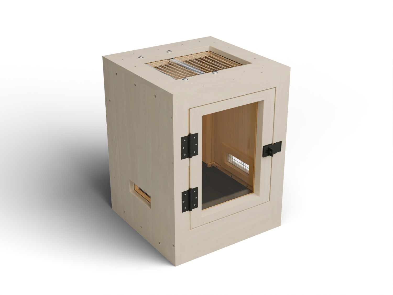
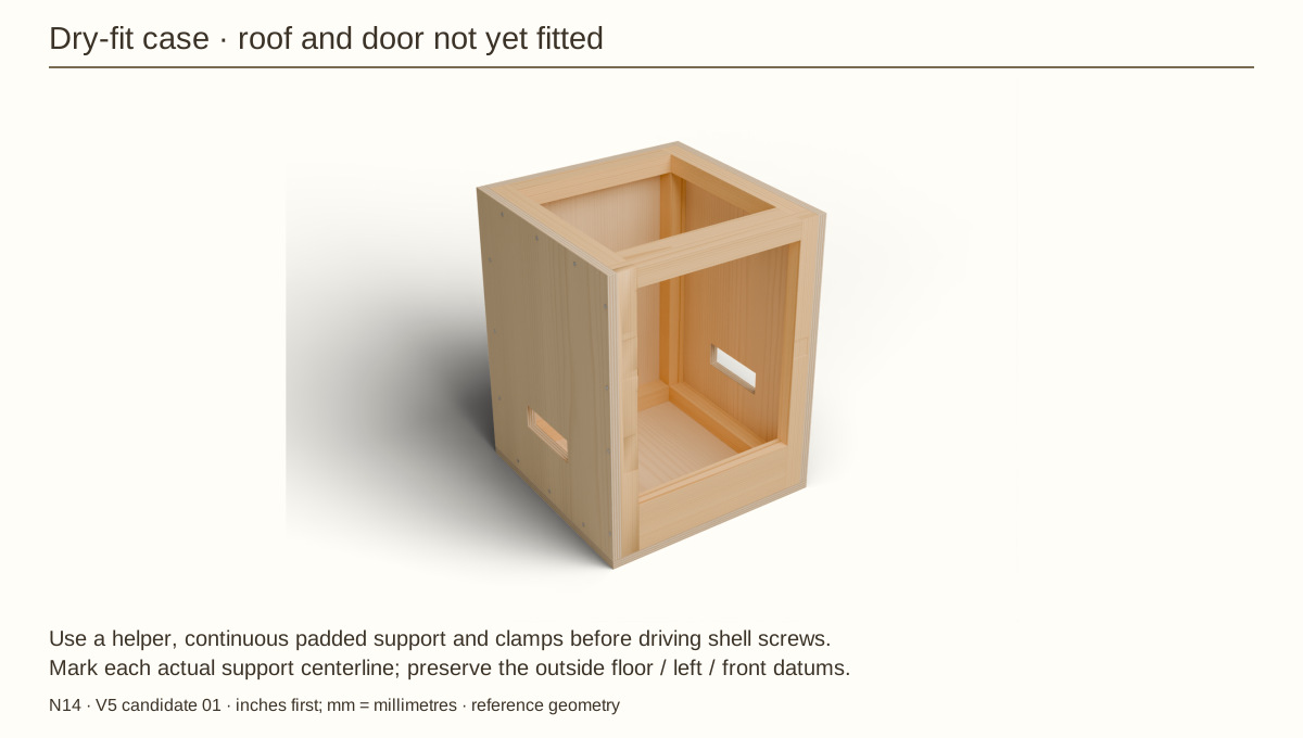
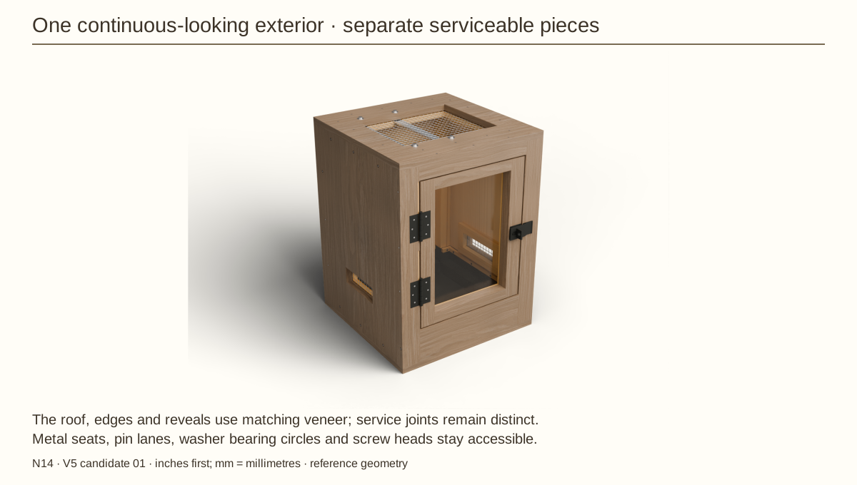
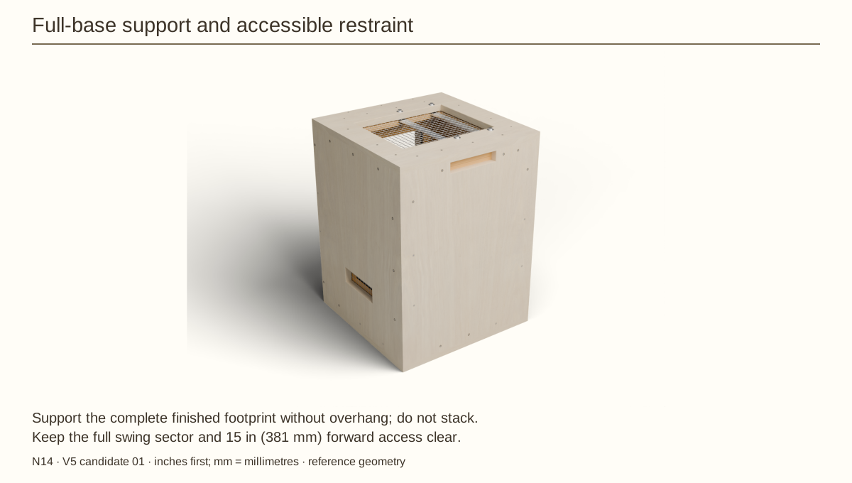
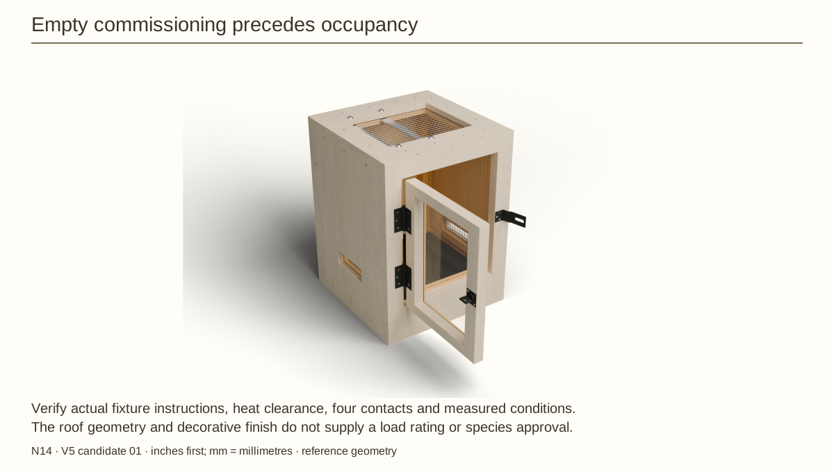
Finish preview: veneer covers the wooden exterior, roof and exposed edges. This guide includes 53 separate veneer pieces, roof and edge coverage, and door clearances for the specified reference stack. Complete the receiving and bond/flatness trials before final cuts. Natural grain and color vary by sheet.
About these previews
Rendered from this enclosure’s own construction model, using maple, white oak or walnut textures on the exterior surfaces. The modeled veneer stack is 0.0305 in (0.77 mm), including its specified finish layers. The cut list, 3D model and PDF include the same 53-piece exterior scheme. Measure the actual cured stack and complete the supplier, balance and hardware trials in operation 1; a color choice is not construction approval.
Texture scans by Jenelle van Heerden via Poly Haven: Maple, White oak, Walnut. CC0 texture license. The scans illustrate natural wood and are not samples from the veneer supplier’s current batch.
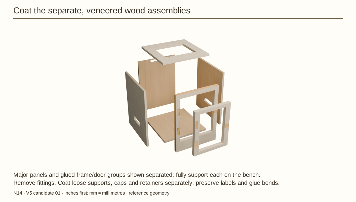
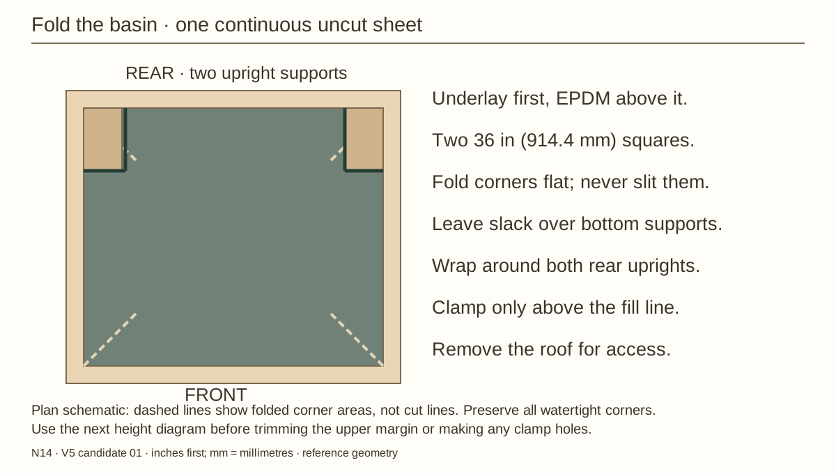
A removable-pin door, removable screened roof and an uncut liner folded around the lower supports. Follow 47 pictured operations, with checks before continuing.
Construction: v5-candidate-01 · Illustrated guide 01. Read the receiving checks before cutting and the installation holds before use.
Guide downloads
All files belong to the same construction revision.
Receive and measure the actual stock and fittings, then complete the illustrated trials before dependent final cuts. These dimensions describe this lined enclosure. A different liner depth, hardware, wood thickness or finish system requires a recheck.
Measurement
Reference
Bare exterior
18 × 18 × 24 in (457.2 × 457.2 × 609.6 mm)
Veneered body reference
18.061 in (458.75 mm) × 18.061 in (458.75 mm) × 24.061 in (611.15 mm)
Clear box before supports / liner
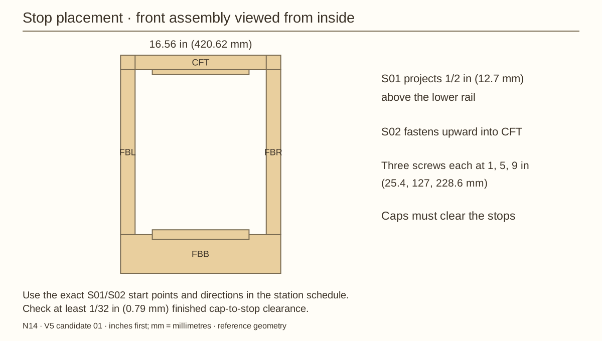
16.56 × 16.03 × 22.56 in (420.62 × 407.16 × 573.02 mm); supports, liner, door parts and equipment reduce usable space
Bare opening
13.56 in (344.42 mm) × 17.06 in (433.32 mm)
Bare door
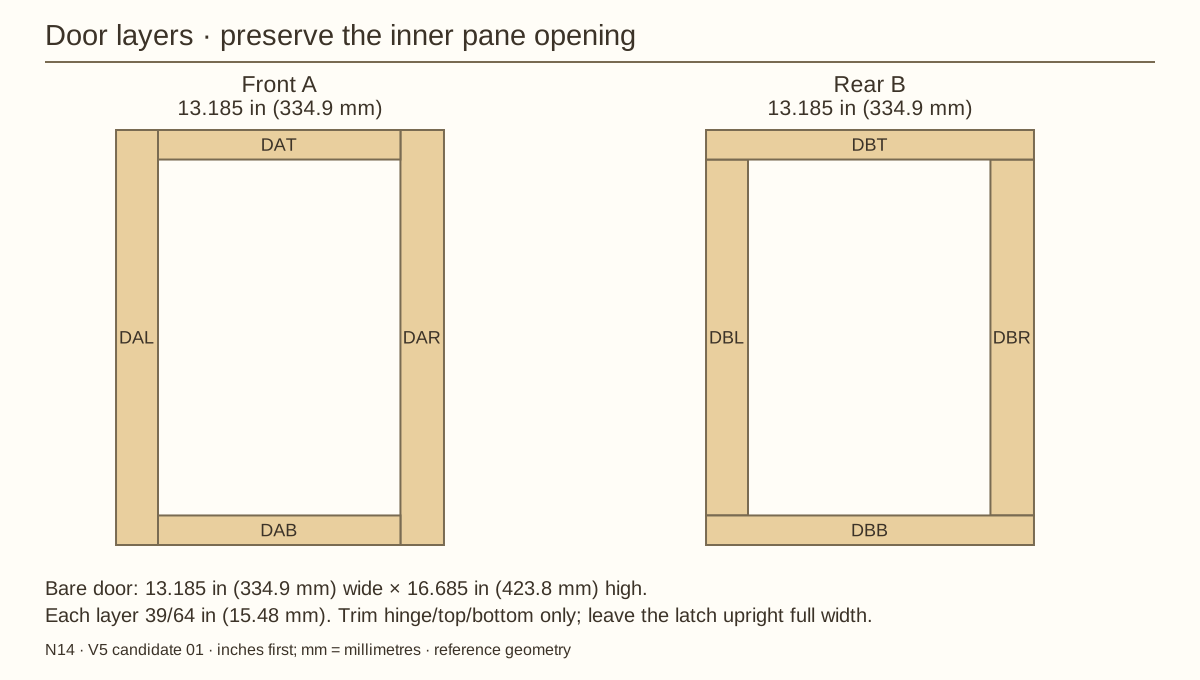
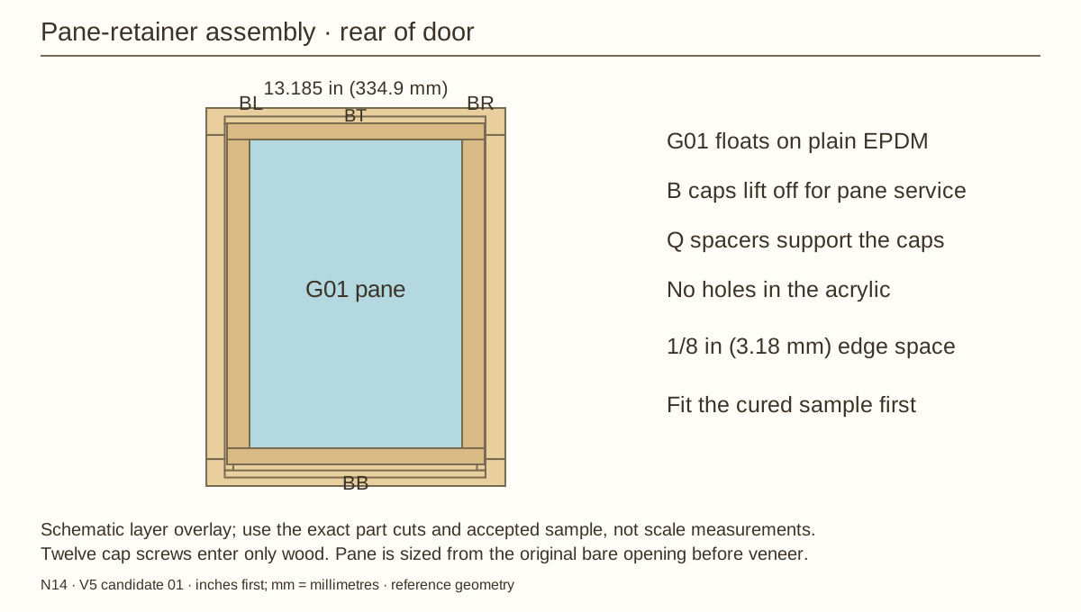
13.185 in (334.9 mm) × 16.685 in (423.8 mm) × 1 7/32 in (30.96 mm)
Finished reference gap
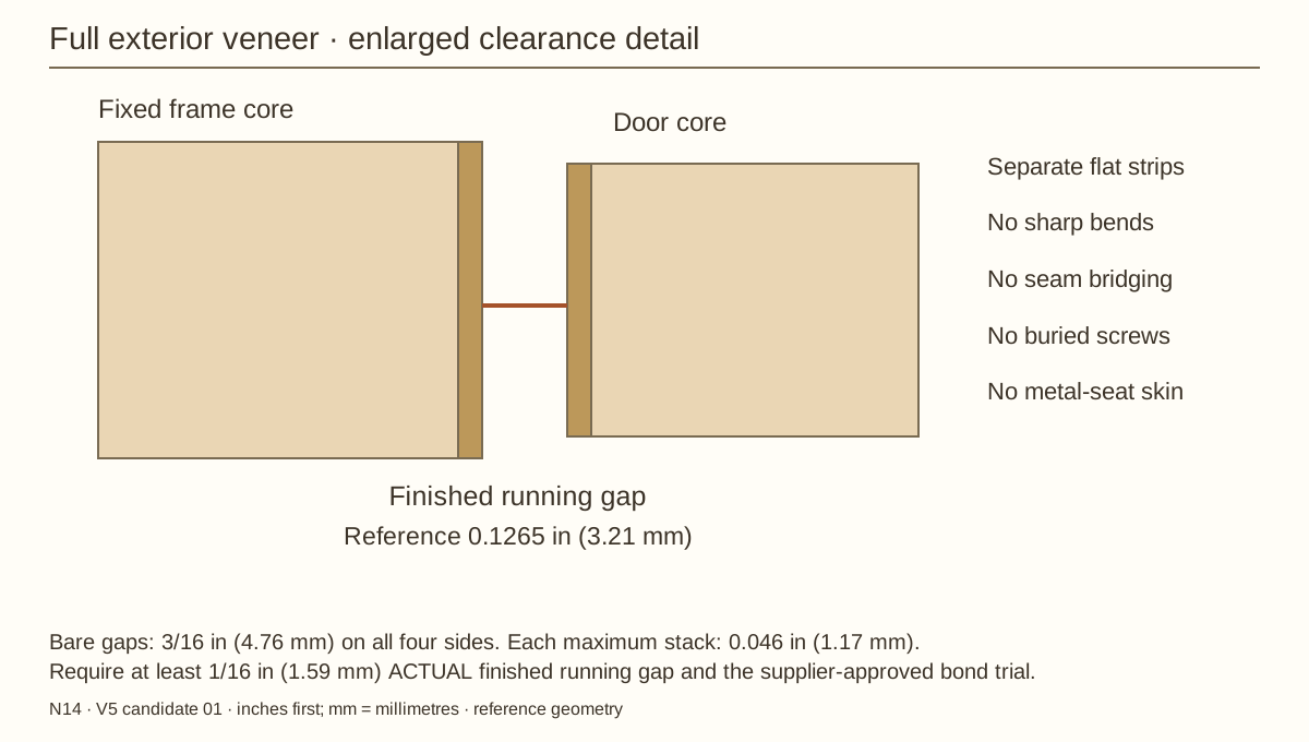
0.1265 in (3.21 mm) per edge; physically require at least 1/16 in (1.59 mm)
Maximum stack budget
0.046 in (1.17 mm) per face; nominal remaining gap 0.0955 in (2.43 mm)
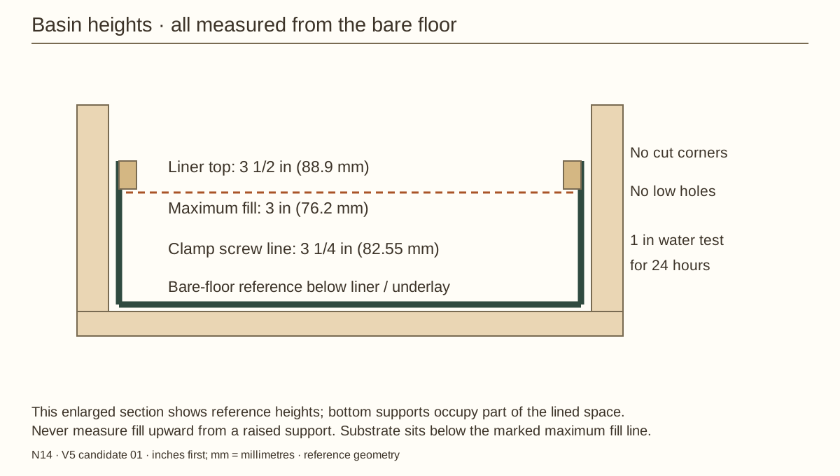
Basin heights above bare floor
Fill 3 in (76.2 mm); clamp screws 3 1/4 in (82.55 mm); liner top 3 1/2 in (88.9 mm)
Service space
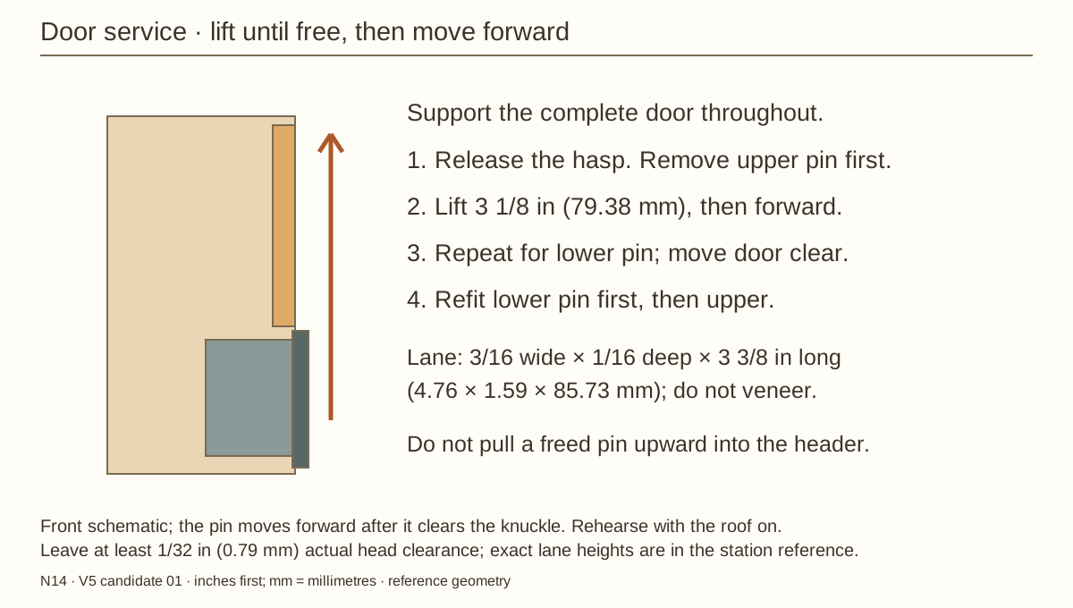
15 in (381 mm) forward plus the full swing sector; each pin lifts 3 1/8 in (79.38 mm), then forward
Measurements: mm means millimetres. Inches come first. Exact nonfractional mating cuts use decimals; fit them with actual gauges and shared marked strips. Coordinates use outside LEFT, FRONT and FLOOR UNDERSIDE unless an operation names a local part edge. The liner’s height datum is the bare floor TOP, 0.72 in (18.29 mm) above the outside floor underside.
Tools, terms and safe setup
Use a flat fully supporting bench, clamps, square, straightedge, tape, caliper, depth stops, marking knife and shared measuring strip. Cutting needs a supported saw setup, jigsaw, suitable router/chisel and a planer or a competent supplier to prepare the specified thicknesses. Follow the machine’s minimum feed length; thickness wide stock before cutting small strips.
Prepare a drill/driver, countersink, 11/64 in (4.37 mm) wood clearance bit, starting 7/64 in (2.78 mm) pine pilot, actual-root-matched small pilots, metal bits, backing boards, snips, hacksaw and files. Use an acrylic-rated blade with full sheet support. Add a veneer scraper, held straightedge, cutting board and sharp knife for the finish option.
Wear eye/hearing protection; control wood dust and ventilate coatings. Protect hands when handling loose sharp mesh or steel. Keep hands, gloves and clothing away from rotating machinery. Secure the work and waste; never hold a small piece in your hand while drilling.
Term
Plain meaning
Cleat / support
Solid wood strip receiving screw threads
Lamination
Two layers glued together, with staggered joints
Pilot / clearance
Thread guide hole in the receiver / larger hole through the first part
Countersink
Shallow cone allowing a flat screw head to sit flush
Datum / story stick
Named measuring edge / marked strip shared between matching parts
Kerf
The material removed by the saw blade
PSA
Pressure-sensitive adhesive supplied on the veneer
EPDM
Ethylene propylene diene monomer rubber; plain cushions and a separate pond liner
No complete affiliate cart has been verified for this revision. Direct product links, exact models, pack sizes and purchase quantities are listed below. Check local stock and received dimensions before ordering.
Shopping list
Materials and hardware
Package quantities are purchase units. Four pine boards include one reserved trial board; two square-pine lengths supply the cleats. Current direct links match this BOM. No affiliate collection has been verified as a complete cart for this revision.
Item / current link
Model and purchase
Check / remaining input
PLY · Birch sanded plywood project panel Direct product listing Reference 0.72 in (18.29 mm); usable 47.75 × 23.75 in (1212.85 × 603.25 mm).
128220 Buy 3 package(s) one panel
Nominal 3/4 in; actual listing 0.72 in. Layout assumes 47.75 × 23.75 in clear panels; measure received stock.
PINE · RELIABILT clear S4S radiata pine board Direct product listing 0.75 × 5.5 × 96 in (19.05 × 139.7 × 2438.4 mm). S4S means surfaced on four sides.
L51244618 Buy 4 package(s) one board
Listing 0.75 × 5.5 × 96 in; three production boards plus one trial board. Plane the required layer thicknesses.
PINE-SQUARE · RELIABILT clear S4S solid pine square board Direct product listing 1.5 × 1.5 × 96 in (38.1 × 38.1 × 2438.4 mm).
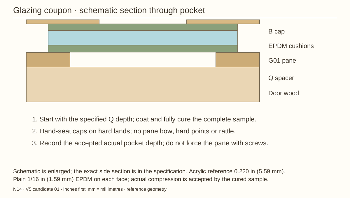
OPTIX 21232102, 0.22 × 24 × 48 in. Measure actual sheet and trial the complete cured glazing pocket.
MESH · Acorn Hardware galvanized steel hardware cloth Direct product listing 1/2 in (12.7 mm) aperture; 36 × 120 in (914.4 × 3048 mm).
HC23610 Buy 1 package(s) one roll
HC23610, 19-gauge, 1/2 in aperture, 36 × 120 in. Verify wire crossings and containment for intended use.
Materials and hardware · continued
Package quantities are purchase units. Four pine boards include one reserved trial board; two square-pine lengths supply the cleats. Current direct links match this BOM. No affiliate collection has been verified as a complete cart for this revision.
Item / current link
Model and purchase
Check / remaining input
HINGE · McMaster-Carr removable-pin surface hinges Direct product listing 3 in (76.2 mm) high; 2.5 in (63.5 mm) open; 0.080 in (2.03 mm) leaf.
1798A21 Buy 1 package(s) two hinges / one pair
1798A21 removable-pin hinge, nominal 3 in length, 2.5 in open width, 0.080 in leaf. Actual receiving trial controls seats, holes and pin travel.
9976524 Buy 1 package(s) 11-piece kit: two brackets, four screws, two clevis pins, two cotters, one cable
Current listing model and package identity match this purchase schedule; verify delivered count, actual dimensions and local fulfillment.
GLUE · Titebond III Ultimate Wood Adhesive, 16 fl oz Direct product listing 16 US fluid ounces (473 mL).
1414 Buy 1 package(s) one bottle
Current listing model and package identity match this purchase schedule; verify delivered count, actual dimensions and local fulfillment.
FINISH · Varathane Triple Thick satin brush-on water-based polyurethane Direct product listing Two US quarts (1.89 L).
284473-7482 Buy 1 package(s) two one-quart cans
284473-7482, two 1-quart containers. Manufacturer guidance: 60–90°F (15.6–32.2°C), RH below 85%, 7 days full cure at 70°F (21.1°C)/50% RH. Exposure and veneer bond compatibility are separate holds.
SCREW-SHELL · Hillman #8 × 1¾″ stainless flat-head wood screws Direct product listing Length 1 3/4 in (44.45 mm).
35312 Buy 2 package(s) 40 screws
Current listing model and package identity match this purchase schedule; verify delivered count, actual dimensions and local fulfillment.
Materials and hardware · continued
Package quantities are purchase units. Four pine boards include one reserved trial board; two square-pine lengths supply the cleats. Current direct links match this BOM. No affiliate collection has been verified as a complete cart for this revision.
Item / current link
Model and purchase
Check / remaining input
SCREW-LAMINATION · Hillman #8 × 1″ zinc-plated flat-head wood screws Direct product listing Length 1 in (25.4 mm).
35053 Buy 1 package(s) 100 screws
Current listing model and package identity match this purchase schedule; verify delivered count, actual dimensions and local fulfillment.
SCREW-RETENTION · Power Pro #8 × 1¼″ stainless flat-head wood screws Direct product listing Length 1 1/4 in (31.75 mm).
42487 Buy 1 package(s) 45 screws
Current listing model and package identity match this purchase schedule; verify delivered count, actual dimensions and local fulfillment.
SCREW-GLAZING · Hillman #4 × 1″ zinc-plated flat-head wood screws Direct product listing Length 1 in (25.4 mm).
40005 Buy 1 package(s) 100 screws
Current listing model and package identity match this purchase schedule; verify delivered count, actual dimensions and local fulfillment.
GASKET · USA Industrials plain closed-cell EPDM strip Direct product listing 1/16 × 3/8 × 120 in (1.59 × 9.53 × 3048 mm).
ZUSAESR-S-25 Buy 1 package(s) one 120-inch strip
ZUSAESR-S-25 plain EPDM 1/16 × 3/8 in × 10 ft. Trial actual compression.
LINER · 45 mil EPDM pond liner, 5′ × 5′ Direct product listing 5 × 5 ft (1.524 × 1.524 m); 45 mil = 0.045 in (1.14 mm).
5 × 5 ft, 45-mil EPDM. Exact thickness, received defects and proposed cleaning/exposure need acceptance.
Materials and hardware · continued
Package quantities are purchase units. Four pine boards include one reserved trial board; two square-pine lengths supply the cleats. Current direct links match this BOM. No affiliate collection has been verified as a complete cart for this revision.
Item / current link
Model and purchase
Check / remaining input
UNDERLAY · Aquascape heavy-duty pond underlayment, 5′ × 10′ Direct product listing 5 × 10 ft (1.524 × 3.048 m).
42135 Buy 1 package(s) one 5′ × 10′ piece
Current manufacturer page confirms 5 × 10 ft size option. Retained 42135 identity needs confirmation on the delivered package.
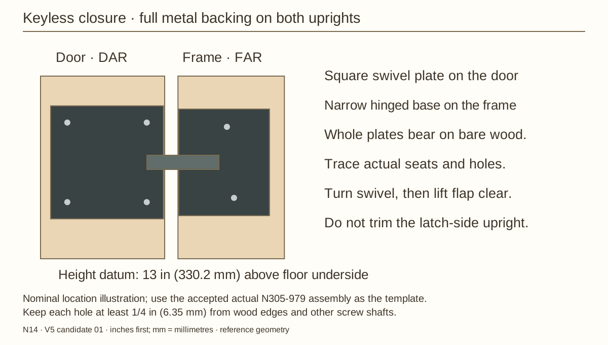
H04 · National Hardware black swivel-staple safety hasp, 3-1/4 inch Direct product listing Nominal 3 1/4 in (82.55 mm) hasp.
N305-979 Buy 1 package(s) 1 per package
N305-979. Manufacturer nominal drawing reviewed; physical trial controls final seats and holes.
H05 · Everbilt #10 × 5/8-inch zinc-plated Phillips flat-head wood screws, 12-pack Direct product listing Length 5/8 in (15.88 mm).
825391 Buy 1 package(s) 12 per package
Current listing model and package identity match this purchase schedule; verify delivered count, actual dimensions and local fulfillment.
11653, solid steel flat 1 × 1/8 in × 36 in. Measure thickness before pocketing.
L16 · Everbilt 1/4-20 × 2-inch zinc-plated round-head machine screws Direct product listing 1/4 in (6.35 mm) diameter × 2 in (50.8 mm) long; retain the specified 20-thread-per-inch fastener.
831561 Buy 2 package(s) 3 per package
Current listing model and package identity match this purchase schedule; verify delivered count, actual dimensions and local fulfillment.
Materials and hardware · continued
Package quantities are purchase units. Four pine boards include one reserved trial board; two square-pine lengths supply the cleats. Current direct links match this BOM. No affiliate collection has been verified as a complete cart for this revision.
Item / current link
Model and purchase
Check / remaining input
L17 · Hillman 1/4-inch zinc-plated flat washers, 3/4-inch OD × 1/16 inch thick Direct product listing 1/4 in (6.35 mm) fastener; outside diameter 3/4 in (19.05 mm), thickness 1/16 in (1.59 mm), subject to receipt.
270055 Buy 8 package(s) 1 per package
270055, 1/4 in washer, one per package; buy eight. Actual outer diameter/thickness must be measured before bearing-seat cuts.
L18 · Hillman 1/4-20 zinc-plated Keps nuts Direct product listing Matches the specified 1/4-20 bolt; 1/4 in (6.35 mm) nominal diameter.
880483 Buy 2 package(s) 2 per package
Current listing model and package identity match this purchase schedule; verify delivered count, actual dimensions and local fulfillment.
VENEER · One selected species, 48 x 96 in factory PSA sheet Direct product listing 48 × 96 in (1219.2 × 2438.4 mm).
Select exact species / standard / 4 x 8 ft / 3M PSA Buy 1 package(s) one sheet
Choose one species / 4 × 8 ft / factory 3M PSA. Special-order, non-returnable backing. Exact selected SKU, bond/dwell and panel balance remain receiving holds.
Cut list
Cut list
One of each ID. Length follows the grain in the allocation. Rough blanks include trimming; finished values are the reference geometry. Use named actual-stock checkpoints for mating cuts. V-parts list the complete 0.0305 in (0.775 mm) modeled surface stack, not purchased veneer thickness.
Part
Rough length × width
Finished length × width × thickness
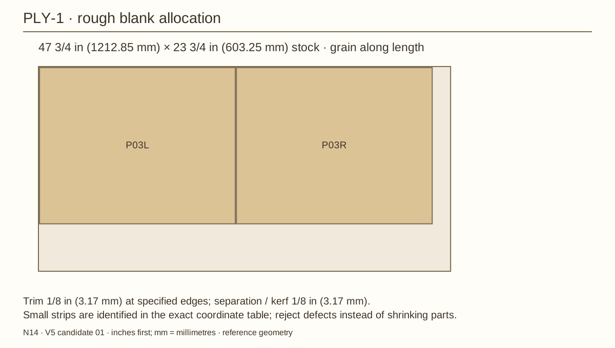
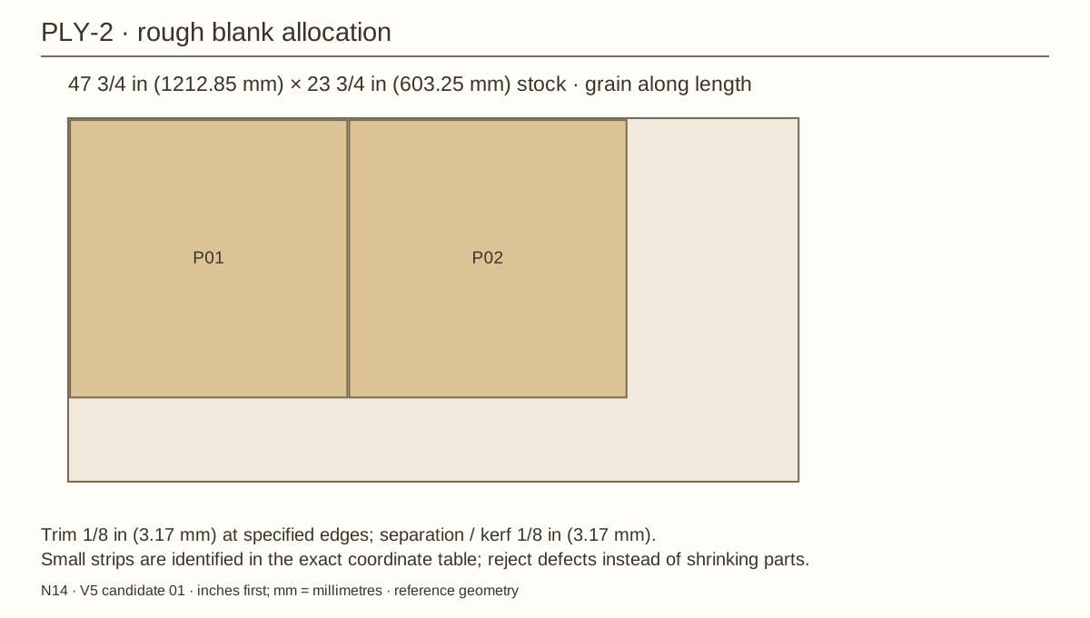
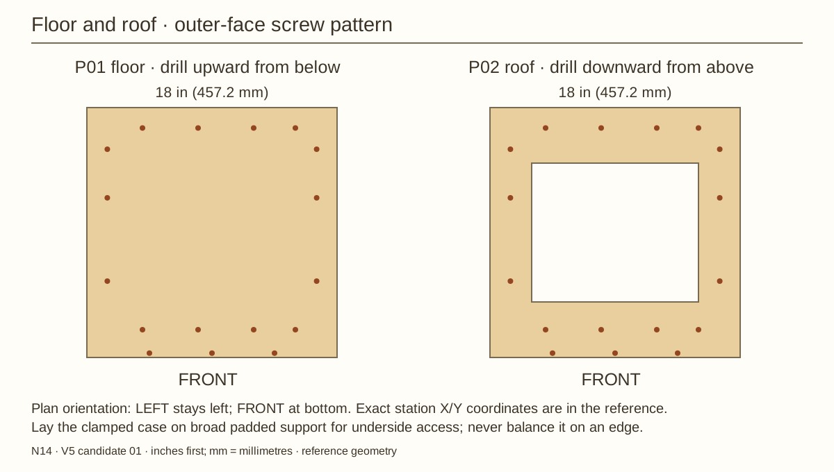
P01 · Solid floor
18 1/8 in (460.38 mm) × 18 1/8 in (460.38 mm)
18 in (457.2 mm) × 18 in (457.2 mm) × 0.72 in (18.29 mm)
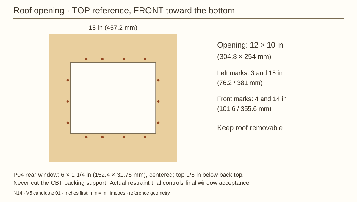
P02 · Removable roof
18 1/8 in (460.38 mm) × 18 1/8 in (460.38 mm)
18 in (457.2 mm) × 18 in (457.2 mm) × 0.72 in (18.29 mm)
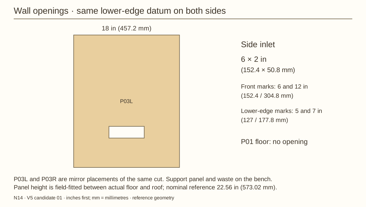
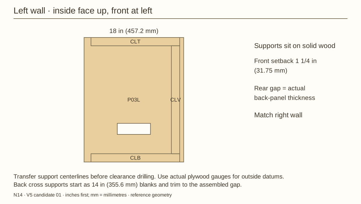
P03L · Left wall
22.685 in (576.2 mm) × 18 1/8 in (460.38 mm)
22.56 in (573.02 mm) × 18 in (457.2 mm) × 0.72 in (18.29 mm)
P03R · Right wall
22.685 in (576.2 mm) × 18 1/8 in (460.38 mm)
22.56 in (573.02 mm) × 18 in (457.2 mm) × 0.72 in (18.29 mm)
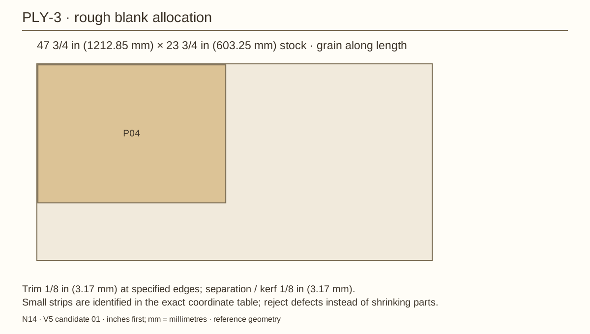
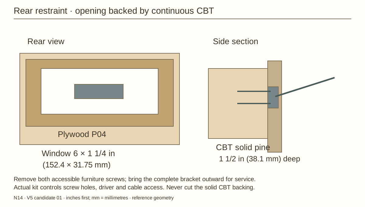
P04 · Back wall
22.685 in (576.2 mm) × 16.685 in (423.8 mm)
22.56 in (573.02 mm) × 16.56 in (420.62 mm) × 0.72 in (18.29 mm)
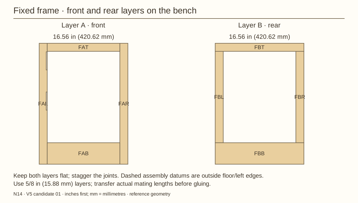
FAL · Fixed frame front layer · left upright
22.685 in (576.2 mm) × 1 5/8 in (41.27 mm)
22.56 in (573.02 mm) × 1 1/2 in (38.1 mm) × 5/8 in (15.88 mm)
FAR · Fixed frame front layer · right upright
22.685 in (576.2 mm) × 1 5/8 in (41.27 mm)
22.56 in (573.02 mm) × 1 1/2 in (38.1 mm) × 5/8 in (15.88 mm)
FAB · Fixed frame front layer · bottom rail
13.685 in (347.6 mm) × 4 1/8 in (104.77 mm)
13.56 in (344.42 mm) × 4 in (101.6 mm) × 5/8 in (15.88 mm)
FAT · Fixed frame front layer · top rail
13.685 in (347.6 mm) × 1 5/8 in (41.27 mm)
13.56 in (344.42 mm) × 1 1/2 in (38.1 mm) × 5/8 in (15.88 mm)
FBL · Fixed frame rear layer · left upright
17.185 in (436.5 mm) × 1 5/8 in (41.27 mm)
17.06 in (433.32 mm) × 1 1/2 in (38.1 mm) × 5/8 in (15.88 mm)
FBR · Fixed frame rear layer · right upright
17.185 in (436.5 mm) × 1 5/8 in (41.27 mm)
17.06 in (433.32 mm) × 1 1/2 in (38.1 mm) × 5/8 in (15.88 mm)
FBB · Fixed frame rear layer · bottom rail
16.685 in (423.8 mm) × 4 1/8 in (104.77 mm)
16.56 in (420.62 mm) × 4 in (101.6 mm) × 5/8 in (15.88 mm)
Cut list · continued
One of each ID. Length follows the grain in the allocation. Rough blanks include trimming; finished values are the reference geometry. Use named actual-stock checkpoints for mating cuts. V-parts list the complete 0.0305 in (0.775 mm) modeled surface stack, not purchased veneer thickness.
Part
Rough length × width
Finished length × width × thickness
FBT · Fixed frame rear layer · top rail
16.685 in (423.8 mm) × 1 5/8 in (41.27 mm)
16.56 in (420.62 mm) × 1 1/2 in (38.1 mm) × 5/8 in (15.88 mm)
DAL · Door front layer · left upright
16.81 in (426.97 mm) × 1 13/16 in (46.04 mm)
16.685 in (423.8 mm) × 1 11/16 in (42.86 mm) × 39/64 in (15.48 mm)
DAR · Door front layer · right upright
16.81 in (426.97 mm) × 1 7/8 in (47.62 mm)
16.685 in (423.8 mm) × 1 3/4 in (44.45 mm) × 39/64 in (15.48 mm)
DAB · Door front layer · bottom rail
9.8725 in (250.76 mm) × 1 5/16 in (33.34 mm)
9.7475 in (247.59 mm) × 1 3/16 in (30.16 mm) × 39/64 in (15.48 mm)
DAT · Door front layer · top rail
9.8725 in (250.76 mm) × 1 5/16 in (33.34 mm)
9.7475 in (247.59 mm) × 1 3/16 in (30.16 mm) × 39/64 in (15.48 mm)
DBL · Door rear layer · left upright
14.435 in (366.65 mm) × 1 13/16 in (46.04 mm)
14.31 in (363.47 mm) × 1 11/16 in (42.86 mm) × 39/64 in (15.48 mm)
DBR · Door rear layer · right upright
14.435 in (366.65 mm) × 1 7/8 in (47.62 mm)
14.31 in (363.47 mm) × 1 3/4 in (44.45 mm) × 39/64 in (15.48 mm)
DBB · Door rear layer · bottom rail
13.31 in (338.07 mm) × 1 5/16 in (33.34 mm)
13.185 in (334.9 mm) × 1 3/16 in (30.16 mm) × 39/64 in (15.48 mm)
DBT · Door rear layer · top rail
13.31 in (338.07 mm) × 1 5/16 in (33.34 mm)
13.185 in (334.9 mm) × 1 3/16 in (30.16 mm) × 39/64 in (15.48 mm)
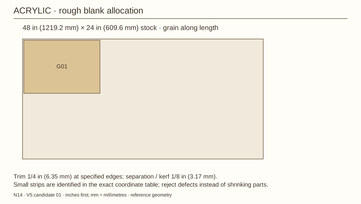
G01 · Removable acrylic pane
15.185 in (385.7 mm) × 10.6225 in (269.81 mm)
15.06 in (382.52 mm) × 10.4975 in (266.64 mm) × 0.22 in (5.59 mm)
QL · Pane pocket spacer · left upright
15.435 in (392.05 mm) × 1/2 in (12.7 mm)
15.31 in (388.87 mm) × 3/8 in (9.52 mm) × 5/16 in (7.94 mm)
QR · Pane pocket spacer · right upright
15.435 in (392.05 mm) × 1/2 in (12.7 mm)
15.31 in (388.87 mm) × 3/8 in (9.52 mm) × 5/16 in (7.94 mm)
Cut list · continued
One of each ID. Length follows the grain in the allocation. Rough blanks include trimming; finished values are the reference geometry. Use named actual-stock checkpoints for mating cuts. V-parts list the complete 0.0305 in (0.775 mm) modeled surface stack, not purchased veneer thickness.
Part
Rough length × width
Finished length × width × thickness
QB · Pane pocket spacer · bottom rail
11.6225 in (295.21 mm) × 7/16 in (11.11 mm)
11.4975 in (292.04 mm) × 5/16 in (7.94 mm) × 5/16 in (7.94 mm)
QT · Pane pocket spacer · top rail
11.6225 in (295.21 mm) × 7/16 in (11.11 mm)
11.4975 in (292.04 mm) × 5/16 in (7.94 mm) × 5/16 in (7.94 mm)
BL · Removable pane cap · left upright
14.685 in (373 mm) × 7/8 in (22.22 mm)
14.56 in (369.82 mm) × 3/4 in (19.05 mm) × 1/4 in (6.35 mm)
BR · Removable pane cap · right upright
14.685 in (373 mm) × 7/8 in (22.22 mm)
14.56 in (369.82 mm) × 3/4 in (19.05 mm) × 1/4 in (6.35 mm)
BB · Removable pane cap · bottom rail
11.6225 in (295.21 mm) × 13/16 in (20.64 mm)
11.4975 in (292.04 mm) × 11/16 in (17.46 mm) × 1/4 in (6.35 mm)
BT · Removable pane cap · top rail
11.6225 in (295.21 mm) × 13/16 in (20.64 mm)
11.4975 in (292.04 mm) × 11/16 in (17.46 mm) × 1/4 in (6.35 mm)
CLV · Left rear upright support
19.685 in (500 mm) × 1 1/2 in (38.1 mm)
19.56 in (496.82 mm) × 1 1/2 in (38.1 mm) × 1 1/2 in (38.1 mm)
CLB · Left lower support
16.155 in (410.34 mm) × 1 1/2 in (38.1 mm)
16.03 in (407.16 mm) × 1 1/2 in (38.1 mm) × 1 1/2 in (38.1 mm)
CLT · Left upper support
16.155 in (410.34 mm) × 1 1/2 in (38.1 mm)
16.03 in (407.16 mm) × 1 1/2 in (38.1 mm) × 1 1/2 in (38.1 mm)
CRV · Right rear upright support
19.685 in (500 mm) × 1 1/2 in (38.1 mm)
19.56 in (496.82 mm) × 1 1/2 in (38.1 mm) × 1 1/2 in (38.1 mm)
CRB · Right lower support
16.155 in (410.34 mm) × 1 1/2 in (38.1 mm)
16.03 in (407.16 mm) × 1 1/2 in (38.1 mm) × 1 1/2 in (38.1 mm)
CRT · Right upper support
16.155 in (410.34 mm) × 1 1/2 in (38.1 mm)
16.03 in (407.16 mm) × 1 1/2 in (38.1 mm) × 1 1/2 in (38.1 mm)
Cut list · continued
One of each ID. Length follows the grain in the allocation. Rough blanks include trimming; finished values are the reference geometry. Use named actual-stock checkpoints for mating cuts. V-parts list the complete 0.0305 in (0.775 mm) modeled surface stack, not purchased veneer thickness.
Part
Rough length × width
Finished length × width × thickness
CBB · Rear lower cross support
14 in (355.6 mm) × 1 1/2 in (38.1 mm)
13.56 in (344.42 mm) × 1 1/2 in (38.1 mm) × 1 1/2 in (38.1 mm)
CFB · Front lower cross support
14 in (355.6 mm) × 1 1/2 in (38.1 mm)
13.56 in (344.42 mm) × 1 1/2 in (38.1 mm) × 1 1/2 in (38.1 mm)
CBT · Rear upper cross support
14 in (355.6 mm) × 1 1/2 in (38.1 mm)
13.56 in (344.42 mm) × 1 1/2 in (38.1 mm) × 1 1/2 in (38.1 mm)
CFT · Front upper cross support
14 in (355.6 mm) × 1 1/2 in (38.1 mm)
13.56 in (344.42 mm) × 1 1/2 in (38.1 mm) × 1 1/2 in (38.1 mm)
S01 · Lower door stop
10 1/8 in (257.18 mm) × 1 1/8 in (28.57 mm)
10 in (254 mm) × 1 in (25.4 mm) × 3/4 in (19.05 mm)
S02 · Upper door stop
10 1/8 in (257.18 mm) × 7/8 in (22.22 mm)
10 in (254 mm) × 3/4 in (19.05 mm) × 1/2 in (12.7 mm)
VLB · Left inlet retainer · bottom
8 1/8 in (206.38 mm) × 1 1/8 in (28.57 mm)
8 in (203.2 mm) × 1 in (25.4 mm) × 3/4 in (19.05 mm)
VLT · Left inlet retainer · top
8 1/8 in (206.38 mm) × 1 1/8 in (28.57 mm)
8 in (203.2 mm) × 1 in (25.4 mm) × 3/4 in (19.05 mm)
VLSF · Left inlet retainer · front end
2 1/8 in (53.97 mm) × 1 1/8 in (28.57 mm)
2 in (50.8 mm) × 1 in (25.4 mm) × 3/4 in (19.05 mm)
VLSB · Left inlet retainer · rear end
2 1/8 in (53.97 mm) × 1 1/8 in (28.57 mm)
2 in (50.8 mm) × 1 in (25.4 mm) × 3/4 in (19.05 mm)
VRB · Right inlet retainer · bottom
8 1/8 in (206.38 mm) × 1 1/8 in (28.57 mm)
8 in (203.2 mm) × 1 in (25.4 mm) × 3/4 in (19.05 mm)
VRT · Right inlet retainer · top
8 1/8 in (206.38 mm) × 1 1/8 in (28.57 mm)
8 in (203.2 mm) × 1 in (25.4 mm) × 3/4 in (19.05 mm)
Cut list · continued
One of each ID. Length follows the grain in the allocation. Rough blanks include trimming; finished values are the reference geometry. Use named actual-stock checkpoints for mating cuts. V-parts list the complete 0.0305 in (0.775 mm) modeled surface stack, not purchased veneer thickness.
Part
Rough length × width
Finished length × width × thickness
VRSF · Right inlet retainer · front end
2 1/8 in (53.97 mm) × 1 1/8 in (28.57 mm)
2 in (50.8 mm) × 1 in (25.4 mm) × 3/4 in (19.05 mm)
VRSB · Right inlet retainer · rear end
2 1/8 in (53.97 mm) × 1 1/8 in (28.57 mm)
2 in (50.8 mm) × 1 in (25.4 mm) × 3/4 in (19.05 mm)
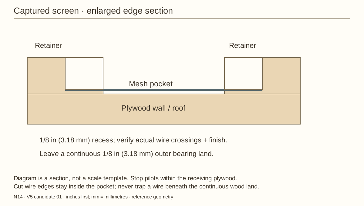
RF · Roof mesh retainer · front
13 5/8 in (346.07 mm) × 1 1/8 in (28.57 mm)
13 1/2 in (342.9 mm) × 1 in (25.4 mm) × 3/4 in (19.05 mm)
RB · Roof mesh retainer · rear
13 5/8 in (346.07 mm) × 1 1/8 in (28.57 mm)
13 1/2 in (342.9 mm) × 1 in (25.4 mm) × 3/4 in (19.05 mm)
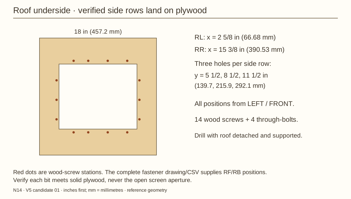
RL · Roof mesh retainer · left
10 1/8 in (257.18 mm) × 7/8 in (22.22 mm)
10 in (254 mm) × 3/4 in (19.05 mm) × 3/4 in (19.05 mm)
RR · Roof mesh retainer · right
10 1/8 in (257.18 mm) × 7/8 in (22.22 mm)
10 in (254 mm) × 3/4 in (19.05 mm) × 3/4 in (19.05 mm)
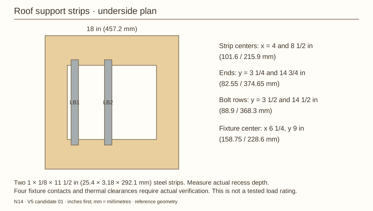
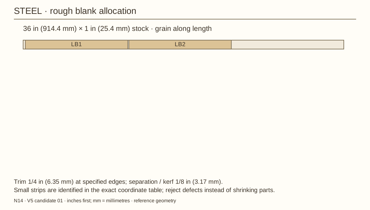
LB1 · Left steel roof strip
11 1/2 in (292.1 mm) × 1 in (25.4 mm)
11 1/2 in (292.1 mm) × 1 in (25.4 mm) × 1/8 in (3.17 mm)
LB2 · Right steel roof strip
11 1/2 in (292.1 mm) × 1 in (25.4 mm)
11 1/2 in (292.1 mm) × 1 in (25.4 mm) × 1/8 in (3.17 mm)
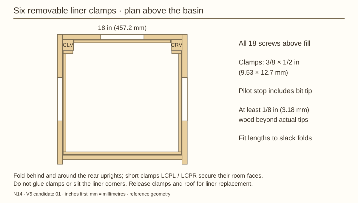
LCL · Removable liner clamp · left
13.745 in (349.12 mm) × 5/8 in (15.88 mm)
13.62 in (345.95 mm) × 1/2 in (12.7 mm) × 3/8 in (9.52 mm)
LCR · Removable liner clamp · right
13.745 in (349.12 mm) × 5/8 in (15.88 mm)
13.62 in (345.95 mm) × 1/2 in (12.7 mm) × 3/8 in (9.52 mm)
LCF · Removable liner clamp · front
16.525 in (419.73 mm) × 5/8 in (15.88 mm)
16.4 in (416.56 mm) × 1/2 in (12.7 mm) × 3/8 in (9.52 mm)
LCB · Removable liner clamp · rear
13.525 in (343.53 mm) × 5/8 in (15.88 mm)
13.4 in (340.36 mm) × 1/2 in (12.7 mm) × 3/8 in (9.52 mm)
Cut list · continued
One of each ID. Length follows the grain in the allocation. Rough blanks include trimming; finished values are the reference geometry. Use named actual-stock checkpoints for mating cuts. V-parts list the complete 0.0305 in (0.775 mm) modeled surface stack, not purchased veneer thickness.
Part
Rough length × width
Finished length × width × thickness
LCPL · Removable liner clamp · left rear post
1.465 in (37.21 mm) × 5/8 in (15.88 mm)
1.34 in (34.04 mm) × 1/2 in (12.7 mm) × 3/8 in (9.52 mm)
LCPR · Removable liner clamp · right rear post
1.465 in (37.21 mm) × 5/8 in (15.88 mm)
1.34 in (34.04 mm) × 1/2 in (12.7 mm) × 3/8 in (9.52 mm)
V-floor-under · Veneer: floor-under
19.061 in (484.15 mm) × 18.561 in (471.45 mm)
18.061 in (458.75 mm) × 18.061 in (458.75 mm) × 0.0305 in (0.77 mm)
V-roof-top · Veneer: roof-top
19.061 in (484.15 mm) × 18.561 in (471.45 mm)
18.061 in (458.75 mm) × 18.061 in (458.75 mm) × 0.0305 in (0.77 mm)
V-P01-front · Veneer: P01-front
19.061 in (484.15 mm) × 1.22 in (30.99 mm)
18.061 in (458.75 mm) × 0.72 in (18.29 mm) × 0.0305 in (0.77 mm)
V-P01-back · Veneer: P01-back
19.061 in (484.15 mm) × 1.22 in (30.99 mm)
18.061 in (458.75 mm) × 0.72 in (18.29 mm) × 0.0305 in (0.77 mm)
V-P01-left · Veneer: P01-left
19 in (482.6 mm) × 1.22 in (30.99 mm)
18 in (457.2 mm) × 0.72 in (18.29 mm) × 0.0305 in (0.77 mm)
V-P01-right · Veneer: P01-right
19 in (482.6 mm) × 1.22 in (30.99 mm)
18 in (457.2 mm) × 0.72 in (18.29 mm) × 0.0305 in (0.77 mm)
V-P02-front · Veneer: P02-front
19.061 in (484.15 mm) × 1.22 in (30.99 mm)
18.061 in (458.75 mm) × 0.72 in (18.29 mm) × 0.0305 in (0.77 mm)
V-P02-back · Veneer: P02-back
19.061 in (484.15 mm) × 1.22 in (30.99 mm)
18.061 in (458.75 mm) × 0.72 in (18.29 mm) × 0.0305 in (0.77 mm)
V-P02-left · Veneer: P02-left
19 in (482.6 mm) × 1.22 in (30.99 mm)
18 in (457.2 mm) × 0.72 in (18.29 mm) × 0.0305 in (0.77 mm)
V-P02-right · Veneer: P02-right
19 in (482.6 mm) × 1.22 in (30.99 mm)
18 in (457.2 mm) × 0.72 in (18.29 mm) × 0.0305 in (0.77 mm)
Cut list · continued
One of each ID. Length follows the grain in the allocation. Rough blanks include trimming; finished values are the reference geometry. Use named actual-stock checkpoints for mating cuts. V-parts list the complete 0.0305 in (0.775 mm) modeled surface stack, not purchased veneer thickness.
Part
Rough length × width
Finished length × width × thickness
V-P03L-outside · Veneer: P03L-outside
23.56 in (598.42 mm) × 18 1/2 in (469.9 mm)
22.56 in (573.02 mm) × 18 in (457.2 mm) × 0.0305 in (0.77 mm)
V-P03L-front · Veneer: P03L-front
23.56 in (598.42 mm) × 1.2505 in (31.76 mm)
22.56 in (573.02 mm) × 0.7505 in (19.06 mm) × 0.0305 in (0.77 mm)
V-P03L-back · Veneer: P03L-back
23.56 in (598.42 mm) × 1.2505 in (31.76 mm)
22.56 in (573.02 mm) × 0.7505 in (19.06 mm) × 0.0305 in (0.77 mm)
V-P03L-vent-near · Veneer: P03L-vent-near
2.939 in (74.65 mm) × 1.22 in (30.99 mm)
1.939 in (49.25 mm) × 0.72 in (18.29 mm) × 0.0305 in (0.77 mm)
V-P03L-vent-far · Veneer: P03L-vent-far
2.939 in (74.65 mm) × 1.22 in (30.99 mm)
1.939 in (49.25 mm) × 0.72 in (18.29 mm) × 0.0305 in (0.77 mm)
V-P03L-vent-bottom · Veneer: P03L-vent-bottom
7 in (177.8 mm) × 1.22 in (30.99 mm)
6 in (152.4 mm) × 0.72 in (18.29 mm) × 0.0305 in (0.77 mm)
V-P03L-vent-top · Veneer: P03L-vent-top
7 in (177.8 mm) × 1.22 in (30.99 mm)
6 in (152.4 mm) × 0.72 in (18.29 mm) × 0.0305 in (0.77 mm)
V-P03R-outside · Veneer: P03R-outside
23.56 in (598.42 mm) × 18 1/2 in (469.9 mm)
22.56 in (573.02 mm) × 18 in (457.2 mm) × 0.0305 in (0.77 mm)
V-P03R-front · Veneer: P03R-front
23.56 in (598.42 mm) × 1.2505 in (31.76 mm)
22.56 in (573.02 mm) × 0.7505 in (19.06 mm) × 0.0305 in (0.77 mm)
V-P03R-back · Veneer: P03R-back
23.56 in (598.42 mm) × 1.2505 in (31.76 mm)
22.56 in (573.02 mm) × 0.7505 in (19.06 mm) × 0.0305 in (0.77 mm)
V-P03R-vent-near · Veneer: P03R-vent-near
2.939 in (74.65 mm) × 1.22 in (30.99 mm)
1.939 in (49.25 mm) × 0.72 in (18.29 mm) × 0.0305 in (0.77 mm)
V-P03R-vent-far · Veneer: P03R-vent-far
2.939 in (74.65 mm) × 1.22 in (30.99 mm)
1.939 in (49.25 mm) × 0.72 in (18.29 mm) × 0.0305 in (0.77 mm)
Cut list · continued
One of each ID. Length follows the grain in the allocation. Rough blanks include trimming; finished values are the reference geometry. Use named actual-stock checkpoints for mating cuts. V-parts list the complete 0.0305 in (0.775 mm) modeled surface stack, not purchased veneer thickness.
Part
Rough length × width
Finished length × width × thickness
V-P03R-vent-bottom · Veneer: P03R-vent-bottom
7 in (177.8 mm) × 1.22 in (30.99 mm)
6 in (152.4 mm) × 0.72 in (18.29 mm) × 0.0305 in (0.77 mm)
V-P03R-vent-top · Veneer: P03R-vent-top
7 in (177.8 mm) × 1.22 in (30.99 mm)
6 in (152.4 mm) × 0.72 in (18.29 mm) × 0.0305 in (0.77 mm)
V-back-outside · Veneer: back-outside
23.56 in (598.42 mm) × 17.06 in (433.32 mm)
22.56 in (573.02 mm) × 16.56 in (420.62 mm) × 0.0305 in (0.77 mm)
V-restraint-left · Veneer: restraint-left
2.189 in (55.6 mm) × 1.22 in (30.99 mm)
1.189 in (30.2 mm) × 0.72 in (18.29 mm) × 0.0305 in (0.77 mm)
V-restraint-right · Veneer: restraint-right
2.189 in (55.6 mm) × 1.22 in (30.99 mm)
1.189 in (30.2 mm) × 0.72 in (18.29 mm) × 0.0305 in (0.77 mm)
V-restraint-lower · Veneer: restraint-lower
7 in (177.8 mm) × 1.22 in (30.99 mm)
6 in (152.4 mm) × 0.72 in (18.29 mm) × 0.0305 in (0.77 mm)
V-restraint-upper · Veneer: restraint-upper
7 in (177.8 mm) × 1.22 in (30.99 mm)
6 in (152.4 mm) × 0.72 in (18.29 mm) × 0.0305 in (0.77 mm)
V-roof-reveal-left · Veneer: roof-reveal-left
10.939 in (277.85 mm) × 1.22 in (30.99 mm)
9.939 in (252.45 mm) × 0.72 in (18.29 mm) × 0.0305 in (0.77 mm)
V-roof-reveal-right · Veneer: roof-reveal-right
10.939 in (277.85 mm) × 1.22 in (30.99 mm)
9.939 in (252.45 mm) × 0.72 in (18.29 mm) × 0.0305 in (0.77 mm)
V-roof-reveal-front · Veneer: roof-reveal-front
13 in (330.2 mm) × 1.22 in (30.99 mm)
12 in (304.8 mm) × 0.72 in (18.29 mm) × 0.0305 in (0.77 mm)
V-roof-reveal-back · Veneer: roof-reveal-back
13 in (330.2 mm) × 1.22 in (30.99 mm)
12 in (304.8 mm) × 0.72 in (18.29 mm) × 0.0305 in (0.77 mm)
V-FAL-face · Veneer: FAL-face
23.56 in (598.42 mm) × 2 in (50.8 mm)
22.56 in (573.02 mm) × 1 1/2 in (38.1 mm) × 0.0305 in (0.77 mm)
Cut list · continued
One of each ID. Length follows the grain in the allocation. Rough blanks include trimming; finished values are the reference geometry. Use named actual-stock checkpoints for mating cuts. V-parts list the complete 0.0305 in (0.775 mm) modeled surface stack, not purchased veneer thickness.
Part
Rough length × width
Finished length × width × thickness
V-FAR-face · Veneer: FAR-face
23.56 in (598.42 mm) × 2 in (50.8 mm)
22.56 in (573.02 mm) × 1 1/2 in (38.1 mm) × 0.0305 in (0.77 mm)
V-FAB-face · Veneer: FAB-face
14.56 in (369.82 mm) × 4 1/2 in (114.3 mm)
13.56 in (344.42 mm) × 4 in (101.6 mm) × 0.0305 in (0.77 mm)
V-FAT-face · Veneer: FAT-face
14.56 in (369.82 mm) × 2 in (50.8 mm)
13.56 in (344.42 mm) × 1 1/2 in (38.1 mm) × 0.0305 in (0.77 mm)
V-DAL-face · Veneer: DAL-face
17.685 in (449.2 mm) × 2 3/16 in (55.56 mm)
16.685 in (423.8 mm) × 1 11/16 in (42.86 mm) × 0.0305 in (0.77 mm)
V-DAR-face · Veneer: DAR-face
17.685 in (449.2 mm) × 2 1/4 in (57.15 mm)
16.685 in (423.8 mm) × 1 3/4 in (44.45 mm) × 0.0305 in (0.77 mm)
V-DAB-face · Veneer: DAB-face
10.7475 in (272.99 mm) × 1 11/16 in (42.86 mm)
9.7475 in (247.59 mm) × 1 3/16 in (30.16 mm) × 0.0305 in (0.77 mm)
V-DAT-face · Veneer: DAT-face
10.7475 in (272.99 mm) × 1 11/16 in (42.86 mm)
9.7475 in (247.59 mm) × 1 3/16 in (30.16 mm) × 0.0305 in (0.77 mm)
V-FAL-opening · Veneer: FAL-opening
18.06 in (458.72 mm) × 1 3/4 in (44.45 mm)
17.06 in (433.32 mm) × 1 1/4 in (31.75 mm) × 0.0305 in (0.77 mm)
V-FAR-opening · Veneer: FAR-opening
18.06 in (458.72 mm) × 1 3/4 in (44.45 mm)
17.06 in (433.32 mm) × 1 1/4 in (31.75 mm) × 0.0305 in (0.77 mm)
V-FAB-opening · Veneer: FAB-opening
14.499 in (368.27 mm) × 1 3/4 in (44.45 mm)
13.499 in (342.87 mm) × 1 1/4 in (31.75 mm) × 0.0305 in (0.77 mm)
V-FAT-opening · Veneer: FAT-opening
14.499 in (368.27 mm) × 1 3/4 in (44.45 mm)
13.499 in (342.87 mm) × 1 1/4 in (31.75 mm) × 0.0305 in (0.77 mm)
V-DAL-outer · Veneer: DAL-outer
17.685 in (449.2 mm) × 1 23/32 in (43.66 mm)
16.685 in (423.8 mm) × 1 7/32 in (30.96 mm) × 0.0305 in (0.77 mm)
Cut list · continued
One of each ID. Length follows the grain in the allocation. Rough blanks include trimming; finished values are the reference geometry. Use named actual-stock checkpoints for mating cuts. V-parts list the complete 0.0305 in (0.775 mm) modeled surface stack, not purchased veneer thickness.
Part
Rough length × width
Finished length × width × thickness
V-DAR-outer · Veneer: DAR-outer
17.685 in (449.2 mm) × 1 23/32 in (43.66 mm)
16.685 in (423.8 mm) × 1 7/32 in (30.96 mm) × 0.0305 in (0.77 mm)
V-DAB-outer · Veneer: DAB-outer
14.246 in (361.85 mm) × 1 23/32 in (43.66 mm)
13.246 in (336.45 mm) × 1 7/32 in (30.96 mm) × 0.0305 in (0.77 mm)
V-DAT-outer · Veneer: DAT-outer
14.246 in (361.85 mm) × 1 23/32 in (43.66 mm)
13.246 in (336.45 mm) × 1 7/32 in (30.96 mm) × 0.0305 in (0.77 mm)
V-DAL-window · Veneer: DAL-window
15.249 in (387.32 mm) × 1 23/32 in (43.66 mm)
14.249 in (361.92 mm) × 1 7/32 in (30.96 mm) × 0.0305 in (0.77 mm)
V-DAR-window · Veneer: DAR-window
15.249 in (387.32 mm) × 1 23/32 in (43.66 mm)
14.249 in (361.92 mm) × 1 7/32 in (30.96 mm) × 0.0305 in (0.77 mm)
V-DAB-window · Veneer: DAB-window
10.7475 in (272.99 mm) × 1 23/32 in (43.66 mm)
9.7475 in (247.59 mm) × 1 7/32 in (30.96 mm) × 0.0305 in (0.77 mm)
V-DAT-window · Veneer: DAT-window
10.7475 in (272.99 mm) × 1 23/32 in (43.66 mm)
9.7475 in (247.59 mm) × 1 7/32 in (30.96 mm) × 0.0305 in (0.77 mm)
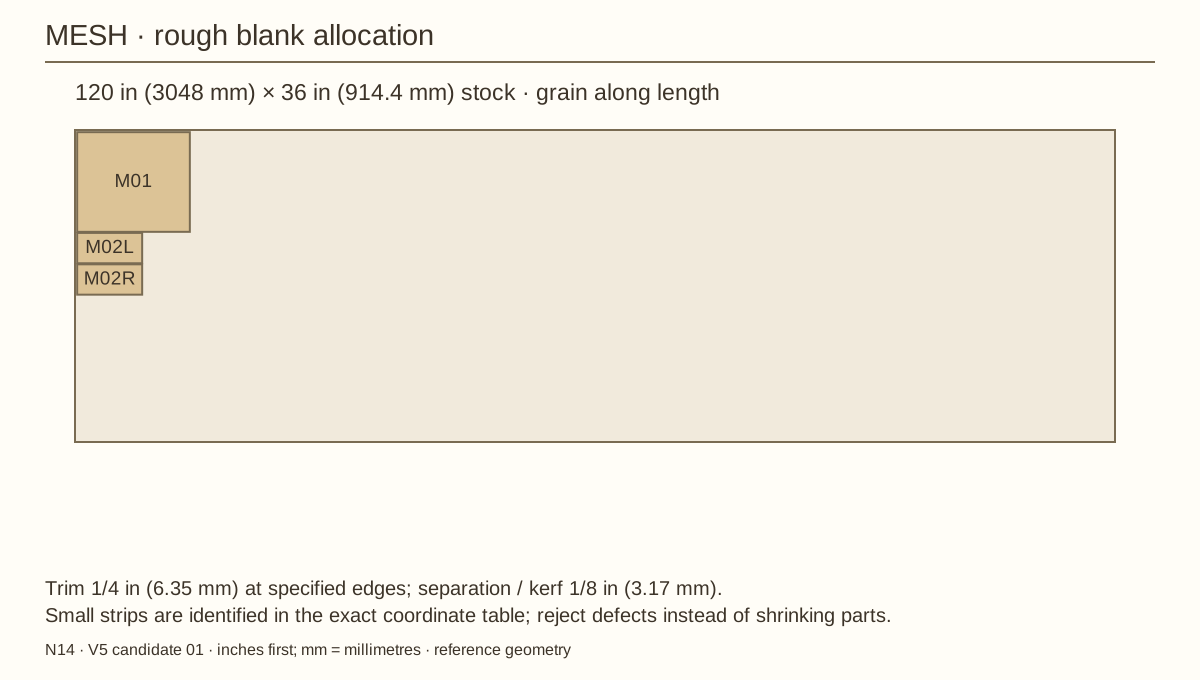
M01 · Roof screen blank
13 in (330.2 mm) × 11 1/2 in (292.1 mm)
13 in (330.2 mm) × 11 1/2 in (292.1 mm) × 0.0836 in (2.12 mm)
M02L · Left inlet screen blank
7 1/2 in (190.5 mm) × 3 1/2 in (88.9 mm)
7 1/2 in (190.5 mm) × 3 1/2 in (88.9 mm) × 0.0836 in (2.12 mm)
M02R · Right inlet screen blank
7 1/2 in (190.5 mm) × 3 1/2 in (88.9 mm)
7 1/2 in (190.5 mm) × 3 1/2 in (88.9 mm) × 0.0836 in (2.12 mm)
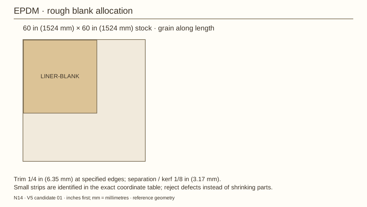
LINER-BLANK · Uncut-corner EPDM basin blank
36 in (914.4 mm) × 36 in (914.4 mm)
36 in (914.4 mm) × 36 in (914.4 mm) × 0.045 in (1.14 mm)
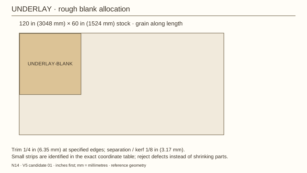
UNDERLAY-BLANK · Protective underlay basin blank
36 in (914.4 mm) × 36 in (914.4 mm)
36 in (914.4 mm) × 36 in (914.4 mm) × Measure received material
Cut list · continued
One of each ID. Length follows the grain in the allocation. Rough blanks include trimming; finished values are the reference geometry. Use named actual-stock checkpoints for mating cuts. V-parts list the complete 0.0305 in (0.775 mm) modeled surface stack, not purchased veneer thickness.
Part
Rough length × width
Finished length × width × thickness
EFB · Plain pane cushion EFB
10.6225 in (269.81 mm) × 3/8 in (9.52 mm)
10.4975 in (266.64 mm) × 3/8 in (9.52 mm) × 1/16 in (1.59 mm)
EFT · Plain pane cushion EFT
10.6225 in (269.81 mm) × 3/8 in (9.52 mm)
10.4975 in (266.64 mm) × 3/8 in (9.52 mm) × 1/16 in (1.59 mm)
EFL · Plain pane cushion EFL
14.435 in (366.65 mm) × 3/8 in (9.52 mm)
14.31 in (363.47 mm) × 3/8 in (9.52 mm) × 1/16 in (1.59 mm)
EFR · Plain pane cushion EFR
14.435 in (366.65 mm) × 3/8 in (9.52 mm)
14.31 in (363.47 mm) × 3/8 in (9.52 mm) × 1/16 in (1.59 mm)
ERB · Plain pane cushion ERB
10.6225 in (269.81 mm) × 3/8 in (9.52 mm)
10.4975 in (266.64 mm) × 1/4 in (6.35 mm) × 1/16 in (1.59 mm)
ERT · Plain pane cushion ERT
10.6225 in (269.81 mm) × 3/8 in (9.52 mm)
10.4975 in (266.64 mm) × 1/4 in (6.35 mm) × 1/16 in (1.59 mm)
ERL · Plain pane cushion ERL
14.685 in (373 mm) × 3/8 in (9.52 mm)
14.56 in (369.82 mm) × 1/4 in (6.35 mm) × 1/16 in (1.59 mm)
ERR · Plain pane cushion ERR
14.685 in (373 mm) × 3/8 in (9.52 mm)
14.56 in (369.82 mm) × 1/4 in (6.35 mm) × 1/16 in (1.59 mm)
Cutting diagrams
PLY-1 · cutting layout
Grain-fixed rough-blank allocation
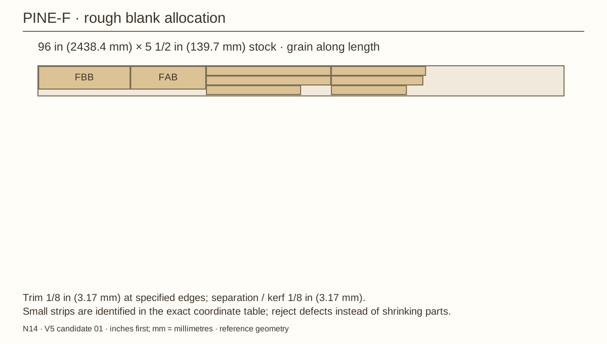
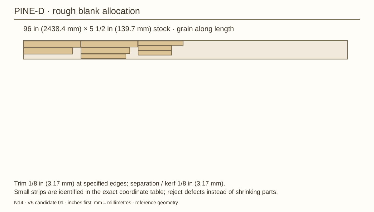
Read the labeled rough dimensions in the cut list. The downloadable layout coordinates preserve the perimeter trim, blade kerf and grain direction. Use full support and a safe straight-cut sequence; replace defective stock rather than shortening parts.
PLY-2 · cutting layout
Grain-fixed rough-blank allocation
Read the labeled rough dimensions in the cut list. The downloadable layout coordinates preserve the perimeter trim, blade kerf and grain direction. Use full support and a safe straight-cut sequence; replace defective stock rather than shortening parts.
PLY-3 · cutting layout
Grain-fixed rough-blank allocation
Read the labeled rough dimensions in the cut list. The downloadable layout coordinates preserve the perimeter trim, blade kerf and grain direction. Use full support and a safe straight-cut sequence; replace defective stock rather than shortening parts.
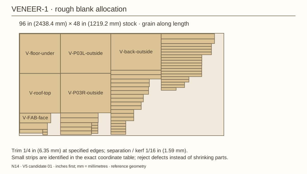
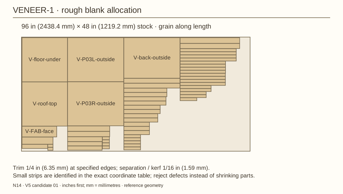
VENEER-1 · cutting layout
Grain-fixed rough-blank allocation
Read the labeled rough dimensions in the cut list. The downloadable layout coordinates preserve the perimeter trim, blade kerf and grain direction. Use full support and a safe straight-cut sequence; replace defective stock rather than shortening parts.
Workshop drawings and measurements
Veneer sheet · exact blank locations
One 96 × 48 in (2438.4 × 1219.2 mm) sheet. X runs along the grain from the left; Y starts at the lower edge. These are rough rectangular blanks. Cutouts and final trimming follow the named part.
Part ID
Start X / Y
Rough length × width
V-floor-under
1/4 in (6.35 mm) / 1/4 in (6.35 mm)
19.061 in (484.15 mm) × 18.561 in (471.45 mm)
V-roof-top
1/4 in (6.35 mm) / 18.8735 in (479.39 mm)
19.061 in (484.15 mm) × 18.561 in (471.45 mm)
V-P03L-outside
19.3735 in (492.09 mm) / 1/4 in (6.35 mm)
23.56 in (598.42 mm) × 18 1/2 in (469.9 mm)
V-P03R-outside
19.3735 in (492.09 mm) / 18 13/16 in (477.84 mm)
23.56 in (598.42 mm) × 18 1/2 in (469.9 mm)
V-back-outside
42.996 in (1092.1 mm) / 1/4 in (6.35 mm)
23.56 in (598.42 mm) × 17.06 in (433.32 mm)
V-FAB-face
1/4 in (6.35 mm) / 37.497 in (952.42 mm)
14.56 in (369.82 mm) × 4 1/2 in (114.3 mm)
V-TRIAL-COUPON
1/4 in (6.35 mm) / 42.0595 in (1068.31 mm)
13 in (330.2 mm) × 3 in (76.2 mm)
V-TRIAL-DOOR
66.6185 in (1692.11 mm) / 1/4 in (6.35 mm)
25 in (635 mm) × 2 3/8 in (60.32 mm)
V-DAR-face
19.3735 in (492.09 mm) / 37 3/8 in (949.32 mm)
17.685 in (449.2 mm) × 2 1/4 in (57.15 mm)
V-DAL-face
19.3735 in (492.09 mm) / 39 11/16 in (1008.06 mm)
17.685 in (449.2 mm) × 2 3/16 in (55.56 mm)
V-TRIAL-FRAME
66.6185 in (1692.11 mm) / 2 11/16 in (68.26 mm)
25 in (635 mm) × 2 1/8 in (53.97 mm)
V-FAL-face
42.996 in (1092.1 mm) / 17.3725 in (441.26 mm)
23.56 in (598.42 mm) × 2 in (50.8 mm)
V-FAR-face
42.996 in (1092.1 mm) / 19.435 in (493.65 mm)
23.56 in (598.42 mm) × 2 in (50.8 mm)
V-FAT-face
19.3735 in (492.09 mm) / 41 15/16 in (1065.21 mm)
14.56 in (369.82 mm) × 2 in (50.8 mm)
V-FAL-opening
42.996 in (1092.1 mm) / 21.4975 in (546.04 mm)
18.06 in (458.72 mm) × 1 3/4 in (44.45 mm)
V-FAR-opening
42.996 in (1092.1 mm) / 23.31 in (592.07 mm)
18.06 in (458.72 mm) × 1 3/4 in (44.45 mm)
Keep grain parallel to X. Retain the 1/4 in (6.35 mm) perimeter and 1/16 in (1.59 mm) cut separation shown in the drawing. The three TRIAL blanks are reserved for receiving checks.
Veneer sheet · exact blank locations
One 96 × 48 in (2438.4 × 1219.2 mm) sheet. X runs along the grain from the left; Y starts at the lower edge. These are rough rectangular blanks. Cutouts and final trimming follow the named part.
Part ID
Start X / Y
Rough length × width
V-FAB-opening
19.3735 in (492.09 mm) / 44 in (1117.6 mm)
14.499 in (368.27 mm) × 1 3/4 in (44.45 mm)
V-FAT-opening
19.3735 in (492.09 mm) / 45 13/16 in (1163.64 mm)
14.499 in (368.27 mm) × 1 3/4 in (44.45 mm)
V-DAL-outer
42.996 in (1092.1 mm) / 25.1225 in (638.11 mm)
17.685 in (449.2 mm) × 1 23/32 in (43.66 mm)
V-DAR-outer
42.996 in (1092.1 mm) / 26.90375 in (683.36 mm)
17.685 in (449.2 mm) × 1 23/32 in (43.66 mm)
V-DAL-window
42.996 in (1092.1 mm) / 28.685 in (728.6 mm)
15.249 in (387.32 mm) × 1 23/32 in (43.66 mm)
V-DAR-window
42.996 in (1092.1 mm) / 30.46625 in (773.84 mm)
15.249 in (387.32 mm) × 1 23/32 in (43.66 mm)
V-DAB-outer
42.996 in (1092.1 mm) / 32.2475 in (819.09 mm)
14.246 in (361.85 mm) × 1 23/32 in (43.66 mm)
V-DAT-outer
42.996 in (1092.1 mm) / 34.02875 in (864.33 mm)
14.246 in (361.85 mm) × 1 23/32 in (43.66 mm)
V-DAB-window
1/4 in (6.35 mm) / 45.122 in (1146.1 mm)
10.7475 in (272.99 mm) × 1 23/32 in (43.66 mm)
V-DAT-window
42.996 in (1092.1 mm) / 35.81 in (909.57 mm)
10.7475 in (272.99 mm) × 1 23/32 in (43.66 mm)
V-DAB-face
42.996 in (1092.1 mm) / 37.59125 in (954.82 mm)
10.7475 in (272.99 mm) × 1 11/16 in (42.86 mm)
V-DAT-face
42.996 in (1092.1 mm) / 39.34125 in (999.27 mm)
10.7475 in (272.99 mm) × 1 11/16 in (42.86 mm)
V-P03L-front
66.6185 in (1692.11 mm) / 4 7/8 in (123.82 mm)
23.56 in (598.42 mm) × 1.2505 in (31.76 mm)
V-P03L-back
66.6185 in (1692.11 mm) / 6.188 in (157.18 mm)
23.56 in (598.42 mm) × 1.2505 in (31.76 mm)
V-P03R-front
66.6185 in (1692.11 mm) / 7.501 in (190.53 mm)
23.56 in (598.42 mm) × 1.2505 in (31.76 mm)
V-P03R-back
66.6185 in (1692.11 mm) / 8.814 in (223.88 mm)
23.56 in (598.42 mm) × 1.2505 in (31.76 mm)
Keep grain parallel to X. Retain the 1/4 in (6.35 mm) perimeter and 1/16 in (1.59 mm) cut separation shown in the drawing. The three TRIAL blanks are reserved for receiving checks.
Veneer sheet · exact blank locations
One 96 × 48 in (2438.4 × 1219.2 mm) sheet. X runs along the grain from the left; Y starts at the lower edge. These are rough rectangular blanks. Cutouts and final trimming follow the named part.
Part ID
Start X / Y
Rough length × width
V-P01-front
66.6185 in (1692.11 mm) / 10.127 in (257.23 mm)
19.061 in (484.15 mm) × 1.22 in (30.99 mm)
V-P01-back
66.6185 in (1692.11 mm) / 11.4095 in (289.8 mm)
19.061 in (484.15 mm) × 1.22 in (30.99 mm)
V-P02-front
66.6185 in (1692.11 mm) / 12.692 in (322.38 mm)
19.061 in (484.15 mm) × 1.22 in (30.99 mm)
V-P02-back
66.6185 in (1692.11 mm) / 13.9745 in (354.95 mm)
19.061 in (484.15 mm) × 1.22 in (30.99 mm)
V-P01-left
66.6185 in (1692.11 mm) / 15.257 in (387.53 mm)
19 in (482.6 mm) × 1.22 in (30.99 mm)
V-P01-right
66.6185 in (1692.11 mm) / 16.5395 in (420.1 mm)
19 in (482.6 mm) × 1.22 in (30.99 mm)
V-P02-left
66.6185 in (1692.11 mm) / 17.822 in (452.68 mm)
19 in (482.6 mm) × 1.22 in (30.99 mm)
V-P02-right
66.6185 in (1692.11 mm) / 19.1045 in (485.25 mm)
19 in (482.6 mm) × 1.22 in (30.99 mm)
V-roof-reveal-front
66.6185 in (1692.11 mm) / 20.387 in (517.83 mm)
13 in (330.2 mm) × 1.22 in (30.99 mm)
V-roof-reveal-back
66.6185 in (1692.11 mm) / 21.6695 in (550.41 mm)
13 in (330.2 mm) × 1.22 in (30.99 mm)
V-roof-reveal-left
66.6185 in (1692.11 mm) / 22.952 in (582.98 mm)
10.939 in (277.85 mm) × 1.22 in (30.99 mm)
V-roof-reveal-right
66.6185 in (1692.11 mm) / 24.2345 in (615.56 mm)
10.939 in (277.85 mm) × 1.22 in (30.99 mm)
V-P03L-vent-bottom
42.996 in (1092.1 mm) / 41.09125 in (1043.72 mm)
7 in (177.8 mm) × 1.22 in (30.99 mm)
V-P03L-vent-top
42.996 in (1092.1 mm) / 42.37375 in (1076.29 mm)
7 in (177.8 mm) × 1.22 in (30.99 mm)
V-P03R-vent-bottom
42.996 in (1092.1 mm) / 43 21/32 in (1108.87 mm)
7 in (177.8 mm) × 1.22 in (30.99 mm)
V-P03R-vent-top
42.996 in (1092.1 mm) / 44.93875 in (1141.44 mm)
7 in (177.8 mm) × 1.22 in (30.99 mm)
Keep grain parallel to X. Retain the 1/4 in (6.35 mm) perimeter and 1/16 in (1.59 mm) cut separation shown in the drawing. The three TRIAL blanks are reserved for receiving checks.
Veneer sheet · exact blank locations
One 96 × 48 in (2438.4 × 1219.2 mm) sheet. X runs along the grain from the left; Y starts at the lower edge. These are rough rectangular blanks. Cutouts and final trimming follow the named part.
Part ID
Start X / Y
Rough length × width
V-restraint-lower
42.996 in (1092.1 mm) / 46.22125 in (1174.02 mm)
7 in (177.8 mm) × 1.22 in (30.99 mm)
V-restraint-upper
66.6185 in (1692.11 mm) / 25.517 in (648.13 mm)
7 in (177.8 mm) × 1.22 in (30.99 mm)
V-P03L-vent-near
33.996 in (863.5 mm) / 41 15/16 in (1065.21 mm)
2.939 in (74.65 mm) × 1.22 in (30.99 mm)
V-P03L-vent-far
33.996 in (863.5 mm) / 43.22 in (1097.79 mm)
2.939 in (74.65 mm) × 1.22 in (30.99 mm)
V-P03R-vent-near
33.996 in (863.5 mm) / 44.5025 in (1130.36 mm)
2.939 in (74.65 mm) × 1.22 in (30.99 mm)
V-P03R-vent-far
33.996 in (863.5 mm) / 45.785 in (1162.94 mm)
2.939 in (74.65 mm) × 1.22 in (30.99 mm)
V-restraint-left
11.06 in (280.92 mm) / 45.122 in (1146.1 mm)
2.189 in (55.6 mm) × 1.22 in (30.99 mm)
V-restraint-right
11.06 in (280.92 mm) / 46.4045 in (1178.67 mm)
2.189 in (55.6 mm) × 1.22 in (30.99 mm)
Keep grain parallel to X. Retain the 1/4 in (6.35 mm) perimeter and 1/16 in (1.59 mm) cut separation shown in the drawing. The three TRIAL blanks are reserved for receiving checks.
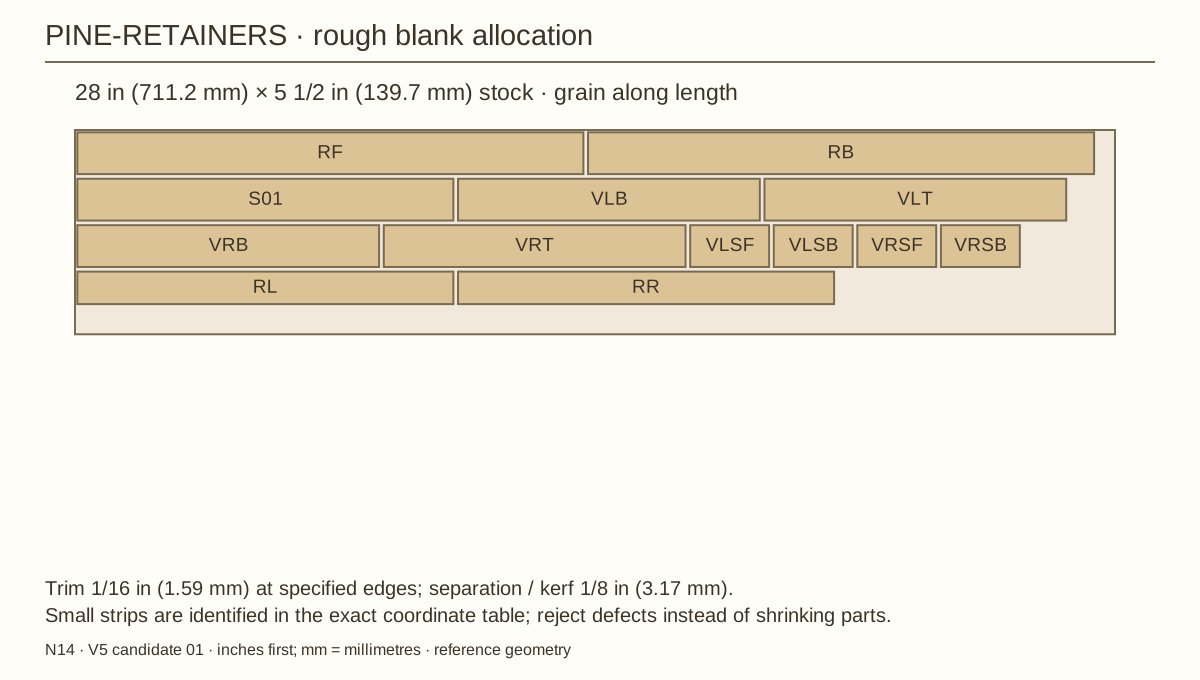
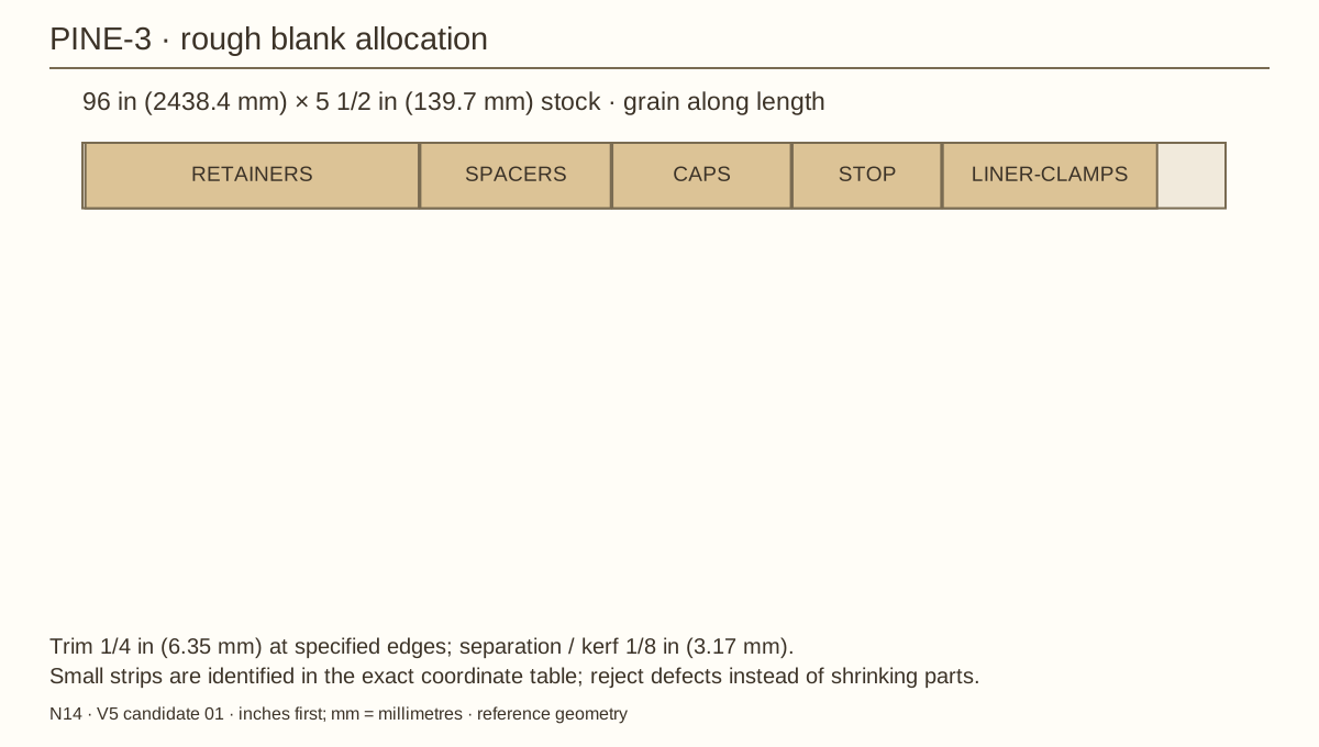
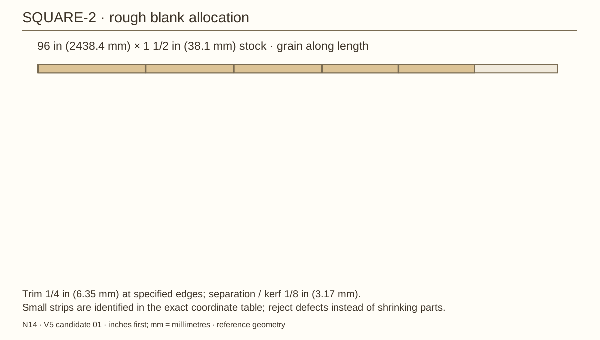
FBB 16.685 in (423.8 mm) × 4 1/8 in (104.77 mm); FAB 13.685 in (347.6 mm) × 4 1/8 in (104.77 mm); FAL 22.685 in (576.2 mm) × 1 5/8 in (41.27 mm); FAR 22.685 in (576.2 mm) × 1 5/8 in (41.27 mm); FBL 17.185 in (436.5 mm) × 1 5/8 in (41.27 mm); FBR 17.185 in (436.5 mm) × 1 5/8 in (41.27 mm); FBT 16.685 in (423.8 mm) × 1 5/8 in (41.27 mm); FAT 13.685 in (347.6 mm) × 1 5/8 in (41.27 mm)
DAR 16.81 in (426.97 mm) × 1 7/8 in (47.62 mm); DBR 14.435 in (366.65 mm) × 1 7/8 in (47.62 mm); DAL 16.81 in (426.97 mm) × 1 13/16 in (46.04 mm); DBL 14.435 in (366.65 mm) × 1 13/16 in (46.04 mm); DBB 13.31 in (338.07 mm) × 1 5/16 in (33.34 mm); DBT 13.31 in (338.07 mm) × 1 5/16 in (33.34 mm); DAB 9.8725 in (250.76 mm) × 1 5/16 in (33.34 mm); DAT 9.8725 in (250.76 mm) × 1 5/16 in (33.34 mm)
RF 13 5/8 in (346.07 mm) × 1 1/8 in (28.57 mm); RB 13 5/8 in (346.07 mm) × 1 1/8 in (28.57 mm); S01 10 1/8 in (257.18 mm) × 1 1/8 in (28.57 mm); VLB 8 1/8 in (206.38 mm) × 1 1/8 in (28.57 mm); VLT 8 1/8 in (206.38 mm) × 1 1/8 in (28.57 mm); VRB 8 1/8 in (206.38 mm) × 1 1/8 in (28.57 mm); VRT 8 1/8 in (206.38 mm) × 1 1/8 in (28.57 mm); VLSF 2 1/8 in (53.97 mm) × 1 1/8 in (28.57 mm); VLSB 2 1/8 in (53.97 mm) × 1 1/8 in (28.57 mm); VRSF 2 1/8 in (53.97 mm) × 1 1/8 in (28.57 mm); VRSB 2 1/8 in (53.97 mm) × 1 1/8 in (28.57 mm); RL 10 1/8 in (257.18 mm) × 7/8 in (22.22 mm); RR 10 1/8 in (257.18 mm) × 7/8 in (22.22 mm)
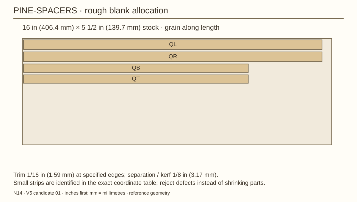
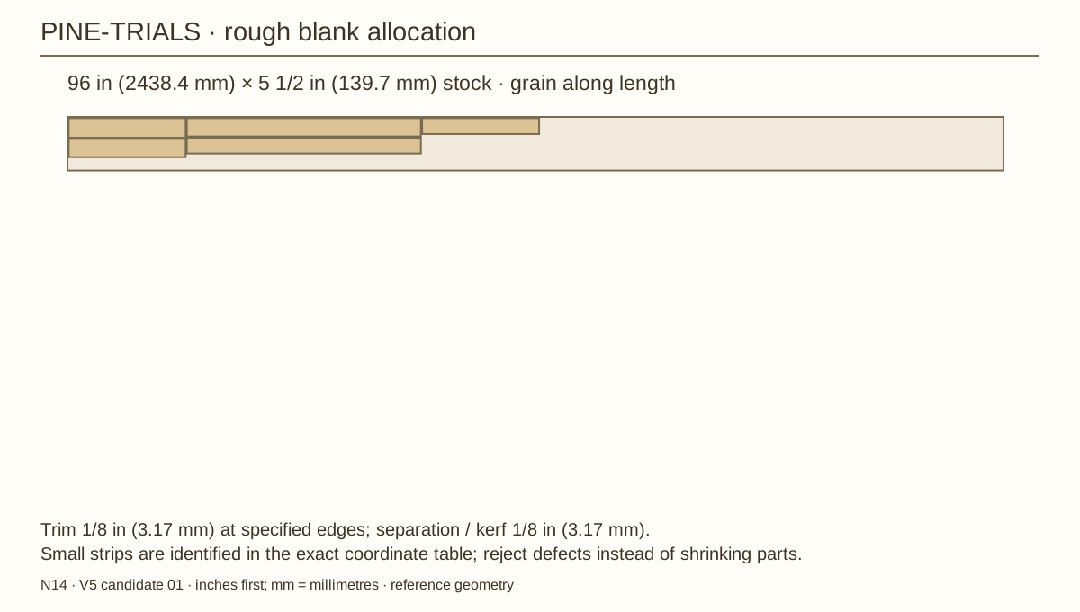
PINE-SPACERS 16 in (406.4 mm) × 5 1/2 in (139.7 mm)
QL 15.435 in (392.05 mm) × 1/2 in (12.7 mm); QR 15.435 in (392.05 mm) × 1/2 in (12.7 mm); QB 11.6225 in (295.21 mm) × 7/16 in (11.11 mm); QT 11.6225 in (295.21 mm) × 7/16 in (11.11 mm)
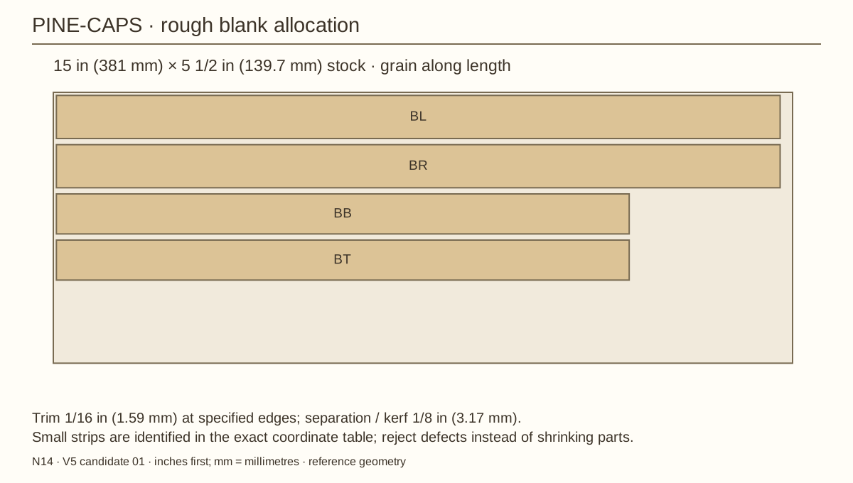
BL 14.685 in (373 mm) × 7/8 in (22.22 mm); BR 14.685 in (373 mm) × 7/8 in (22.22 mm); BB 11.6225 in (295.21 mm) × 13/16 in (20.64 mm); BT 11.6225 in (295.21 mm) × 13/16 in (20.64 mm)
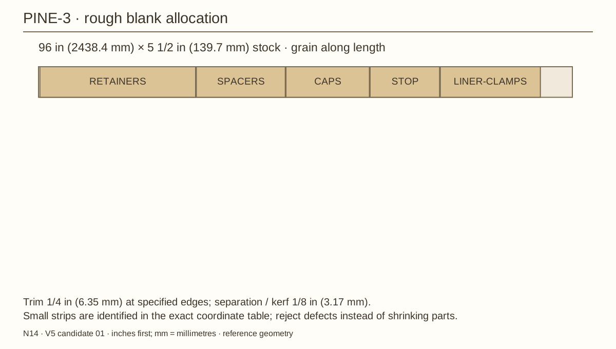
Broad board-three blanks are thicknessed while wide. Follow machine minimum feed lengths; do not feed the finished small strips. The full coordinate drawings in the ZIP show the sublayouts, trim and separation. For the single veneer sheet, keep all grain along the allocated length and reserve the labeled trial pieces.
Stock allocation · continued
Stock / diagram
Ordered rough allocations
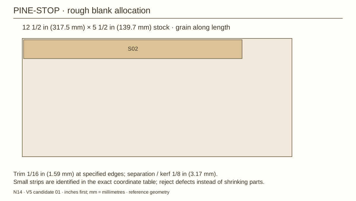
PINE-STOP 12 1/2 in (317.5 mm) × 5 1/2 in (139.7 mm)
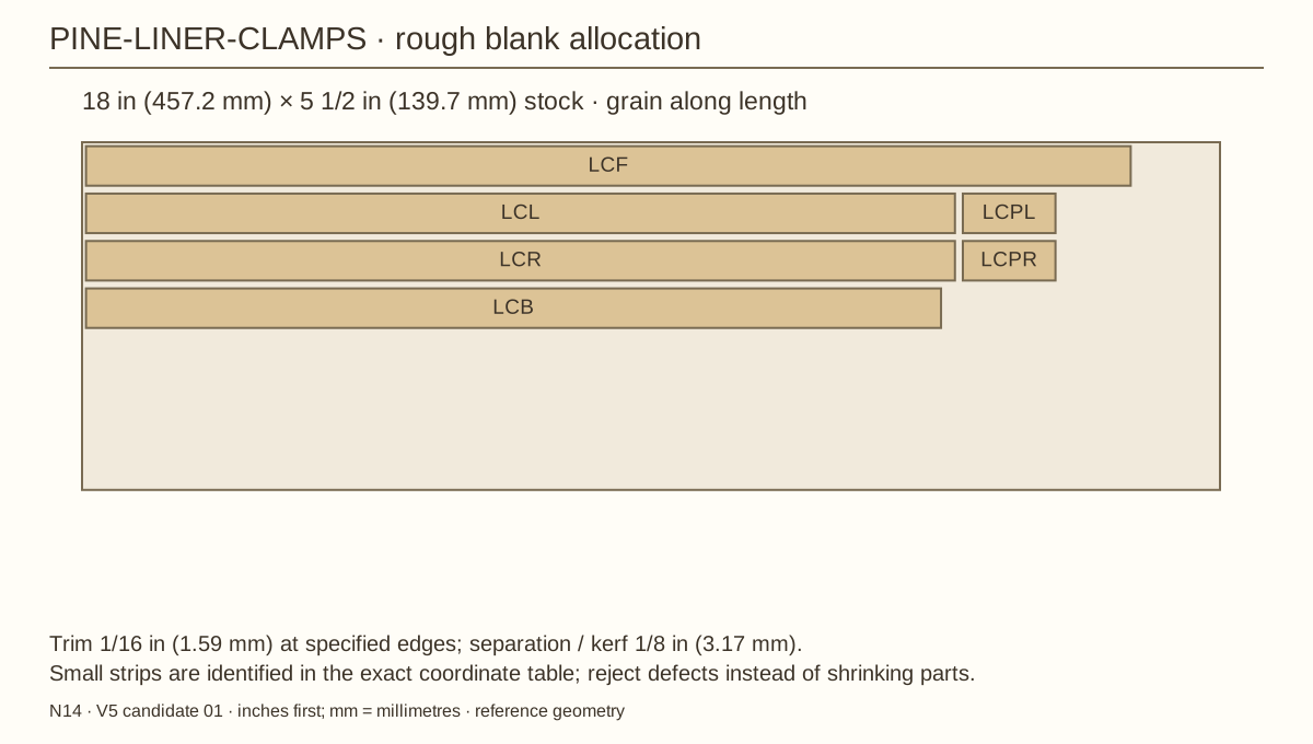
LCF 16.525 in (419.73 mm) × 5/8 in (15.88 mm); LCL 13.745 in (349.12 mm) × 5/8 in (15.88 mm); LCR 13.745 in (349.12 mm) × 5/8 in (15.88 mm); LCB 13.525 in (343.53 mm) × 5/8 in (15.88 mm); LCPL 1.465 in (37.21 mm) × 5/8 in (15.88 mm); LCPR 1.465 in (37.21 mm) × 5/8 in (15.88 mm)
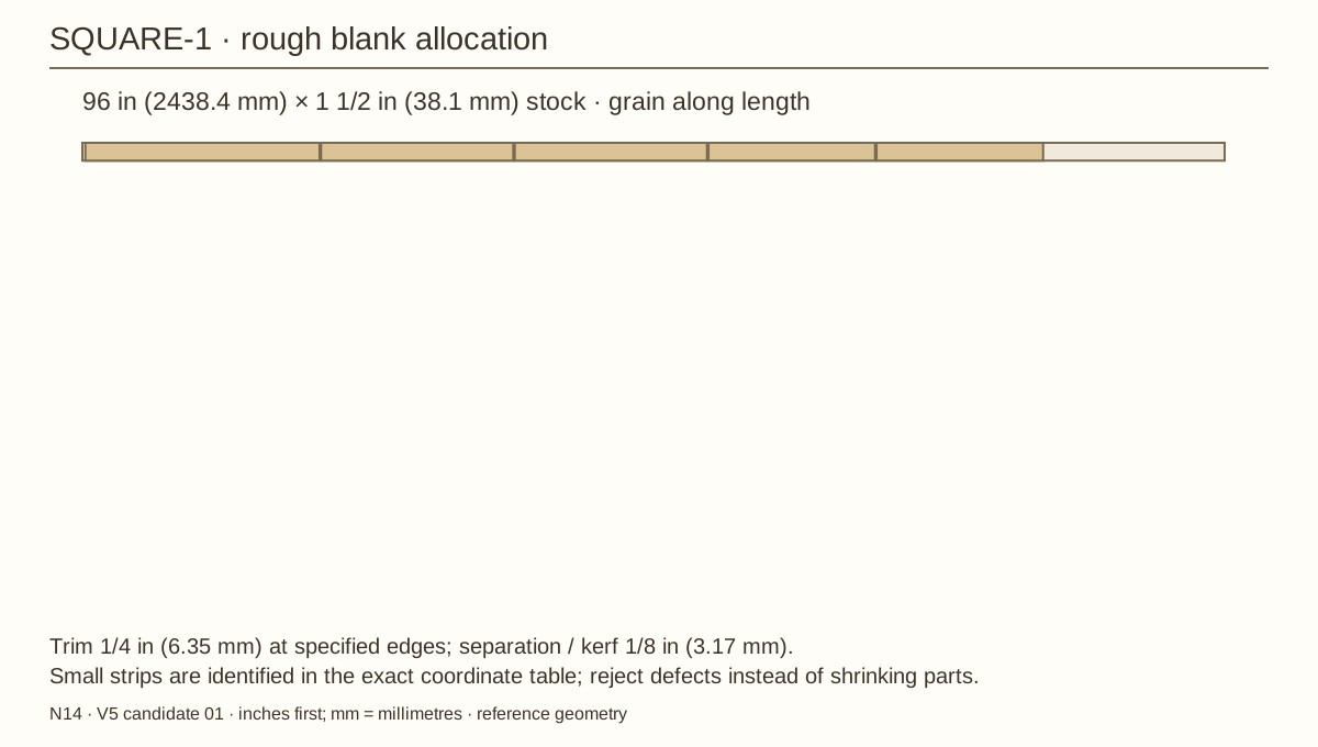
CLV 19.685 in (500 mm) × 1 1/2 in (38.1 mm); CLB 16.155 in (410.34 mm) × 1 1/2 in (38.1 mm); CRB 16.155 in (410.34 mm) × 1 1/2 in (38.1 mm); CBB 14 in (355.6 mm) × 1 1/2 in (38.1 mm); CBT 14 in (355.6 mm) × 1 1/2 in (38.1 mm)
Broad board-three blanks are thicknessed while wide. Follow machine minimum feed lengths; do not feed the finished small strips. The full coordinate drawings in the ZIP show the sublayouts, trim and separation. For the single veneer sheet, keep all grain along the allocated length and reserve the labeled trial pieces.
EFB 10.6225 in (269.81 mm) × 3/8 in (9.52 mm); EFT 10.6225 in (269.81 mm) × 3/8 in (9.52 mm); EFL 14.435 in (366.65 mm) × 3/8 in (9.52 mm); EFR 14.435 in (366.65 mm) × 3/8 in (9.52 mm); ERB 10.6225 in (269.81 mm) × 3/8 in (9.52 mm); ERT 10.6225 in (269.81 mm) × 3/8 in (9.52 mm); ERL 14.685 in (373 mm) × 3/8 in (9.52 mm); ERR 14.685 in (373 mm) × 3/8 in (9.52 mm)
Broad board-three blanks are thicknessed while wide. Follow machine minimum feed lengths; do not feed the finished small strips. The full coordinate drawings in the ZIP show the sublayouts, trim and separation. For the single veneer sheet, keep all grain along the allocated length and reserve the labeled trial pieces.
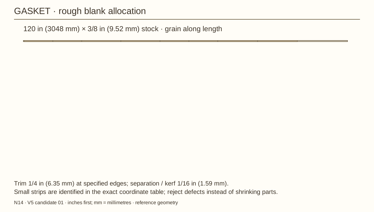
LB1 11 1/2 in (292.1 mm) × 1 in (25.4 mm); LB2 11 1/2 in (292.1 mm) × 1 in (25.4 mm)
Broad board-three blanks are thicknessed while wide. Follow machine minimum feed lengths; do not feed the finished small strips. The full coordinate drawings in the ZIP show the sublayouts, trim and separation. For the single veneer sheet, keep all grain along the allocated length and reserve the labeled trial pieces.
How to use the exact station schedule
Every start point is X from outside LEFT, Y from outside FRONT, Z from the FLOOR UNDERSIDE, in inches with millimetres below. The direction is the drilling/screw direction. Draw those datums on a setup board before loose door/frame work. Physical hardware is traced from accepted samples; nominal points are cross-checks, not a substitute for the trial.
Shell screws start at the new veneer surface. Their reference ends are 0.0305 in (0.775 mm) shallower in the receiver than in the raw case. Veneer is excluded from hinge, latch and upper washer bearing seats, so those hardware coordinates remain on their original planes.
X / Y / Z from outside LEFT / FRONT / FLOOR UNDERSIDE. Start coordinates include the veneer entry shift where applicable. Trace actual hardware only after its accepted sample fit.
ID
Through → receiver
Start X / Y / Z
Direction / nominal length
J001
P03L → CLB
-0.0305 / 4 / 1.47 in -0.77 / 101.60 / 37.34 mm
+X · 1 3/4 in (44.45 mm)
J002
P03L → CLB
-0.0305 / 9 / 1.47 in -0.77 / 228.60 / 37.34 mm
+X · 1 3/4 in (44.45 mm)
J003
P03L → CLB
-0.0305 / 14 / 1.47 in -0.77 / 355.60 / 37.34 mm
+X · 1 3/4 in (44.45 mm)
J004
P03L → CLT
-0.0305 / 4 / 22.53 in -0.77 / 101.60 / 572.26 mm
+X · 1 3/4 in (44.45 mm)
J005
P03L → CLT
-0.0305 / 9 / 22.53 in -0.77 / 228.60 / 572.26 mm
+X · 1 3/4 in (44.45 mm)
J006
P03L → CLT
-0.0305 / 14 / 22.53 in -0.77 / 355.60 / 572.26 mm
+X · 1 3/4 in (44.45 mm)
J007
P03L → CLV
-0.0305 / 16.53 / 6 in -0.77 / 419.86 / 152.40 mm
+X · 1 3/4 in (44.45 mm)
J008
P03L → CLV
-0.0305 / 16.53 / 12 in -0.77 / 419.86 / 304.80 mm
+X · 1 3/4 in (44.45 mm)
J010
P03L → CLV
-0.0305 / 16.53 / 18 in -0.77 / 419.86 / 457.20 mm
+X · 1 3/4 in (44.45 mm)
J011
P03L → FAL
-0.0305 / 0.3125 / 3 in -0.77 / 7.94 / 76.20 mm
+X · 1 3/4 in (44.45 mm)
J012
P03L → FAL
-0.0305 / 0.3125 / 10 in -0.77 / 7.94 / 254.00 mm
+X · 1 3/4 in (44.45 mm)
J013
P03L → FAL
-0.0305 / 0.3125 / 15 in -0.77 / 7.94 / 381.00 mm
+X · 1 3/4 in (44.45 mm)
J015
P03L → FAL
-0.0305 / 0.3125 / 21 in -0.77 / 7.94 / 533.40 mm
+X · 1 3/4 in (44.45 mm)
J016
P03R → CRB
18.0305 / 4 / 1.47 in 457.97 / 101.60 / 37.34 mm
−X · 1 3/4 in (44.45 mm)
J017
P03R → CRB
18.0305 / 9 / 1.47 in 457.97 / 228.60 / 37.34 mm
−X · 1 3/4 in (44.45 mm)
J018
P03R → CRB
18.0305 / 14 / 1.47 in 457.97 / 355.60 / 37.34 mm
−X · 1 3/4 in (44.45 mm)
J019
P03R → CRT
18.0305 / 4 / 22.53 in 457.97 / 101.60 / 572.26 mm
−X · 1 3/4 in (44.45 mm)
J020
P03R → CRT
18.0305 / 9 / 22.53 in 457.97 / 228.60 / 572.26 mm
−X · 1 3/4 in (44.45 mm)
Fastener stations · 19–36
X / Y / Z from outside LEFT / FRONT / FLOOR UNDERSIDE. Start coordinates include the veneer entry shift where applicable. Trace actual hardware only after its accepted sample fit.
ID
Through → receiver
Start X / Y / Z
Direction / nominal length
J021
P03R → CRT
18.0305 / 14 / 22.53 in 457.97 / 355.60 / 572.26 mm
−X · 1 3/4 in (44.45 mm)
J022
P03R → CRV
18.0305 / 16.53 / 6 in 457.97 / 419.86 / 152.40 mm
−X · 1 3/4 in (44.45 mm)
J023
P03R → CRV
18.0305 / 16.53 / 12 in 457.97 / 419.86 / 304.80 mm
−X · 1 3/4 in (44.45 mm)
J025
P03R → CRV
18.0305 / 16.53 / 18 in 457.97 / 419.86 / 457.20 mm
−X · 1 3/4 in (44.45 mm)
J026
P03R → FAR
18.0305 / 0.3125 / 3 in 457.97 / 7.94 / 76.20 mm
−X · 1 3/4 in (44.45 mm)
J027
P03R → FAR
18.0305 / 0.3125 / 10 in 457.97 / 7.94 / 254.00 mm
−X · 1 3/4 in (44.45 mm)
J028
P03R → FAR
18.0305 / 0.3125 / 15 in 457.97 / 7.94 / 381.00 mm
−X · 1 3/4 in (44.45 mm)
J030
P03R → FAR
18.0305 / 0.3125 / 21 in 457.97 / 7.94 / 533.40 mm
−X · 1 3/4 in (44.45 mm)
J031
P04 → CLV
1.47 / 18.0305 / 8 in 37.34 / 457.97 / 203.20 mm
−Y · 1 3/4 in (44.45 mm)
J032
P04 → CLV
1.47 / 18.0305 / 14 in 37.34 / 457.97 / 355.60 mm
−Y · 1 3/4 in (44.45 mm)
J033
P04 → CLV
1.47 / 18.0305 / 20 in 37.34 / 457.97 / 508.00 mm
−Y · 1 3/4 in (44.45 mm)
J035
P04 → CRV
16.53 / 18.0305 / 8 in 419.86 / 457.97 / 203.20 mm
−Y · 1 3/4 in (44.45 mm)
J036
P04 → CRV
16.53 / 18.0305 / 14 in 419.86 / 457.97 / 355.60 mm
−Y · 1 3/4 in (44.45 mm)
J037
P04 → CRV
16.53 / 18.0305 / 20 in 419.86 / 457.97 / 508.00 mm
−Y · 1 3/4 in (44.45 mm)
J039
P04 → CBB
5 / 18.0305 / 1.47 in 127.00 / 457.97 / 37.34 mm
−Y · 1 3/4 in (44.45 mm)
J040
P04 → CBB
9 / 18.0305 / 1.47 in 228.60 / 457.97 / 37.34 mm
−Y · 1 3/4 in (44.45 mm)
J041
P04 → CBB
13 / 18.0305 / 1.47 in 330.20 / 457.97 / 37.34 mm
−Y · 1 3/4 in (44.45 mm)
J042
P04 → CBT
3 / 18.0305 / 22.53 in 76.20 / 457.97 / 572.26 mm
−Y · 1 3/4 in (44.45 mm)
Fastener stations · 37–54
X / Y / Z from outside LEFT / FRONT / FLOOR UNDERSIDE. Start coordinates include the veneer entry shift where applicable. Trace actual hardware only after its accepted sample fit.
ID
Through → receiver
Start X / Y / Z
Direction / nominal length
J043
P04 → CBT
5 / 18.0305 / 22.53 in 127.00 / 457.97 / 572.26 mm
−Y · 1 3/4 in (44.45 mm)
J044
P04 → CBT
13 / 18.0305 / 22.53 in 330.20 / 457.97 / 572.26 mm
−Y · 1 3/4 in (44.45 mm)
J045
P01 → CLB
1.47 / 5.5 / -0.0305 in 37.34 / 139.70 / -0.77 mm
+Z · 1 3/4 in (44.45 mm)
J046
P01 → CLB
1.47 / 11.5 / -0.0305 in 37.34 / 292.10 / -0.77 mm
+Z · 1 3/4 in (44.45 mm)
J047
P01 → CLB
1.47 / 15 / -0.0305 in 37.34 / 381.00 / -0.77 mm
+Z · 1 3/4 in (44.45 mm)
J048
P01 → CRB
16.53 / 5.5 / -0.0305 in 419.86 / 139.70 / -0.77 mm
+Z · 1 3/4 in (44.45 mm)
J049
P01 → CRB
16.53 / 11.5 / -0.0305 in 419.86 / 292.10 / -0.77 mm
+Z · 1 3/4 in (44.45 mm)
J050
P01 → CRB
16.53 / 15 / -0.0305 in 419.86 / 381.00 / -0.77 mm
+Z · 1 3/4 in (44.45 mm)
J051
P01 → CFB
4 / 2 / -0.0305 in 101.60 / 50.80 / -0.77 mm
+Z · 1 3/4 in (44.45 mm)
J052
P01 → CFB
8 / 2 / -0.0305 in 203.20 / 50.80 / -0.77 mm
+Z · 1 3/4 in (44.45 mm)
J053
P01 → CFB
12 / 2 / -0.0305 in 304.80 / 50.80 / -0.77 mm
+Z · 1 3/4 in (44.45 mm)
J054
P01 → CFB
15 / 2 / -0.0305 in 381.00 / 50.80 / -0.77 mm
+Z · 1 3/4 in (44.45 mm)
J055
P01 → CBB
4 / 16.53 / -0.0305 in 101.60 / 419.86 / -0.77 mm
+Z · 1 3/4 in (44.45 mm)
J056
P01 → CBB
8 / 16.53 / -0.0305 in 203.20 / 419.86 / -0.77 mm
+Z · 1 3/4 in (44.45 mm)
J057
P01 → CBB
12 / 16.53 / -0.0305 in 304.80 / 419.86 / -0.77 mm
+Z · 1 3/4 in (44.45 mm)
J058
P01 → CBB
15 / 16.53 / -0.0305 in 381.00 / 419.86 / -0.77 mm
+Z · 1 3/4 in (44.45 mm)
J059
P01 → FAB
4.5 / 0.3125 / -0.0305 in 114.30 / 7.94 / -0.77 mm
+Z · 1 3/4 in (44.45 mm)
J060
P01 → FAB
9 / 0.3125 / -0.0305 in 228.60 / 7.94 / -0.77 mm
+Z · 1 3/4 in (44.45 mm)
Fastener stations · 55–72
X / Y / Z from outside LEFT / FRONT / FLOOR UNDERSIDE. Start coordinates include the veneer entry shift where applicable. Trace actual hardware only after its accepted sample fit.
ID
Through → receiver
Start X / Y / Z
Direction / nominal length
J061
P01 → FAB
13.5 / 0.3125 / -0.0305 in 342.90 / 7.94 / -0.77 mm
+Z · 1 3/4 in (44.45 mm)
J062
P02 → CLT
1.47 / 5.5 / 24.0305 in 37.34 / 139.70 / 610.37 mm
−Z · 1 3/4 in (44.45 mm)
J063
P02 → CLT
1.47 / 11.5 / 24.0305 in 37.34 / 292.10 / 610.37 mm
−Z · 1 3/4 in (44.45 mm)
J064
P02 → CLT
1.47 / 15 / 24.0305 in 37.34 / 381.00 / 610.37 mm
−Z · 1 3/4 in (44.45 mm)
J065
P02 → CRT
16.53 / 5.5 / 24.0305 in 419.86 / 139.70 / 610.37 mm
−Z · 1 3/4 in (44.45 mm)
J066
P02 → CRT
16.53 / 11.5 / 24.0305 in 419.86 / 292.10 / 610.37 mm
−Z · 1 3/4 in (44.45 mm)
J067
P02 → CRT
16.53 / 15 / 24.0305 in 419.86 / 381.00 / 610.37 mm
−Z · 1 3/4 in (44.45 mm)
J068
P02 → CFT
4 / 2 / 24.0305 in 101.60 / 50.80 / 610.37 mm
−Z · 1 3/4 in (44.45 mm)
J069
P02 → CFT
8 / 2 / 24.0305 in 203.20 / 50.80 / 610.37 mm
−Z · 1 3/4 in (44.45 mm)
J070
P02 → CFT
12 / 2 / 24.0305 in 304.80 / 50.80 / 610.37 mm
−Z · 1 3/4 in (44.45 mm)
J071
P02 → CFT
15 / 2 / 24.0305 in 381.00 / 50.80 / 610.37 mm
−Z · 1 3/4 in (44.45 mm)
J072
P02 → CBT
4 / 16.53 / 24.0305 in 101.60 / 419.86 / 610.37 mm
−Z · 1 3/4 in (44.45 mm)
J073
P02 → CBT
8 / 16.53 / 24.0305 in 203.20 / 419.86 / 610.37 mm
−Z · 1 3/4 in (44.45 mm)
J074
P02 → CBT
12 / 16.53 / 24.0305 in 304.80 / 419.86 / 610.37 mm
−Z · 1 3/4 in (44.45 mm)
J075
P02 → CBT
15 / 16.53 / 24.0305 in 381.00 / 419.86 / 610.37 mm
−Z · 1 3/4 in (44.45 mm)
J076
P02 → FAT
4.5 / 0.3125 / 24.0305 in 114.30 / 7.94 / 610.37 mm
−Z · 1 3/4 in (44.45 mm)
J077
P02 → FAT
9 / 0.3125 / 24.0305 in 228.60 / 7.94 / 610.37 mm
−Z · 1 3/4 in (44.45 mm)
J078
P02 → FAT
13.5 / 0.3125 / 24.0305 in 342.90 / 7.94 / 610.37 mm
−Z · 1 3/4 in (44.45 mm)
Fastener stations · 73–90
X / Y / Z from outside LEFT / FRONT / FLOOR UNDERSIDE. Start coordinates include the veneer entry shift where applicable. Trace actual hardware only after its accepted sample fit.
ID
Through → receiver
Start X / Y / Z
Direction / nominal length
J079
FBB → FAL
1.47 / 1.25 / 1.47 in 37.34 / 31.75 / 37.34 mm
−Y · 1 in (25.4 mm)
J080
FBB → FAL
1.47 / 1.25 / 4 in 37.34 / 31.75 / 101.60 mm
−Y · 1 in (25.4 mm)
J081
FBL → FAL
1.47 / 1.25 / 8 in 37.34 / 31.75 / 203.20 mm
−Y · 1 in (25.4 mm)
J082
FBL → FAL
1.47 / 1.25 / 14 in 37.34 / 31.75 / 355.60 mm
−Y · 1 in (25.4 mm)
J083
FBL → FAL
1.47 / 1.25 / 20 in 37.34 / 31.75 / 508.00 mm
−Y · 1 in (25.4 mm)
J086
FBT → FAL
1.47 / 1.25 / 22.53 in 37.34 / 31.75 / 572.26 mm
−Y · 1 in (25.4 mm)
J087
FBB → FAR
16.53 / 1.25 / 1.47 in 419.86 / 31.75 / 37.34 mm
−Y · 1 in (25.4 mm)
J088
FBB → FAR
16.53 / 1.25 / 4 in 419.86 / 31.75 / 101.60 mm
−Y · 1 in (25.4 mm)
J089
FBR → FAR
16.53 / 1.25 / 8 in 419.86 / 31.75 / 203.20 mm
−Y · 1 in (25.4 mm)
J090
FBR → FAR
16.53 / 1.25 / 14 in 419.86 / 31.75 / 355.60 mm
−Y · 1 in (25.4 mm)
J091
FBR → FAR
16.53 / 1.25 / 20 in 419.86 / 31.75 / 508.00 mm
−Y · 1 in (25.4 mm)
J094
FBT → FAR
16.53 / 1.25 / 22.53 in 419.86 / 31.75 / 572.26 mm
−Y · 1 in (25.4 mm)
J095
FBB → FAB
5.5 / 1.25 / 2.5 in 139.70 / 31.75 / 63.50 mm
−Y · 1 in (25.4 mm)
J096
FBB → FAB
11.5 / 1.25 / 2.5 in 292.10 / 31.75 / 63.50 mm
−Y · 1 in (25.4 mm)
J097
FBT → FAT
5.5 / 1.25 / 22.53 in 139.70 / 31.75 / 572.26 mm
−Y · 1 in (25.4 mm)
J098
FBT → FAT
11.5 / 1.25 / 22.53 in 292.10 / 31.75 / 572.26 mm
−Y · 1 in (25.4 mm)
J099
DBB → DAL
3.22 / 1.25 / 5.47 in 81.79 / 31.75 / 138.94 mm
−Y · 1 in (25.4 mm)
J100
DBL → DAL
3.22 / 1.25 / 10 in 81.79 / 31.75 / 254.00 mm
−Y · 1 in (25.4 mm)
Fastener stations · 91–108
X / Y / Z from outside LEFT / FRONT / FLOOR UNDERSIDE. Start coordinates include the veneer entry shift where applicable. Trace actual hardware only after its accepted sample fit.
ID
Through → receiver
Start X / Y / Z
Direction / nominal length
J101
DBL → DAL
3.22 / 1.25 / 16 in 81.79 / 31.75 / 406.40 mm
−Y · 1 in (25.4 mm)
J104
DBT → DAL
3.22 / 1.25 / 21.03 in 81.79 / 31.75 / 534.16 mm
−Y · 1 in (25.4 mm)
J105
DBB → DAR
14.7175 / 1.25 / 5.47 in 373.82 / 31.75 / 138.94 mm
−Y · 1 in (25.4 mm)
J106
DBR → DAR
14.7175 / 1.25 / 10 in 373.82 / 31.75 / 254.00 mm
−Y · 1 in (25.4 mm)
J107
DBR → DAR
14.7175 / 1.25 / 16 in 373.82 / 31.75 / 406.40 mm
−Y · 1 in (25.4 mm)
J110
DBT → DAR
14.7175 / 1.25 / 21.03 in 373.82 / 31.75 / 534.16 mm
−Y · 1 in (25.4 mm)
J111
DBB → DAB
9 / 1.25 / 5.47 in 228.60 / 31.75 / 138.94 mm
−Y · 1 in (25.4 mm)
J112
DBT → DAT
9 / 1.25 / 21.03 in 228.60 / 31.75 / 534.16 mm
−Y · 1 in (25.4 mm)
J113
VLB → P03L
1.47 / 6 / 5.22 in 37.34 / 152.40 / 132.59 mm
−X · 1 1/4 in (31.75 mm)
J114
VLB → P03L
1.47 / 9 / 5.22 in 37.34 / 228.60 / 132.59 mm
−X · 1 1/4 in (31.75 mm)
J115
VLB → P03L
1.47 / 12 / 5.22 in 37.34 / 304.80 / 132.59 mm
−X · 1 1/4 in (31.75 mm)
J116
VLT → P03L
1.47 / 6 / 8.22 in 37.34 / 152.40 / 208.79 mm
−X · 1 1/4 in (31.75 mm)
J117
VLT → P03L
1.47 / 9 / 8.22 in 37.34 / 228.60 / 208.79 mm
−X · 1 1/4 in (31.75 mm)
J118
VLT → P03L
1.47 / 12 / 8.22 in 37.34 / 304.80 / 208.79 mm
−X · 1 1/4 in (31.75 mm)
J119
VLSF → P03L
1.47 / 5.5 / 6.72 in 37.34 / 139.70 / 170.69 mm
−X · 1 1/4 in (31.75 mm)
J120
VLSB → P03L
1.47 / 12.5 / 6.72 in 37.34 / 317.50 / 170.69 mm
−X · 1 1/4 in (31.75 mm)
J121
VRB → P03R
16.53 / 6 / 5.22 in 419.86 / 152.40 / 132.59 mm
+X · 1 1/4 in (31.75 mm)
J122
VRB → P03R
16.53 / 9 / 5.22 in 419.86 / 228.60 / 132.59 mm
+X · 1 1/4 in (31.75 mm)
Fastener stations · 109–126
X / Y / Z from outside LEFT / FRONT / FLOOR UNDERSIDE. Start coordinates include the veneer entry shift where applicable. Trace actual hardware only after its accepted sample fit.
ID
Through → receiver
Start X / Y / Z
Direction / nominal length
J123
VRB → P03R
16.53 / 12 / 5.22 in 419.86 / 304.80 / 132.59 mm
+X · 1 1/4 in (31.75 mm)
J124
VRT → P03R
16.53 / 6 / 8.22 in 419.86 / 152.40 / 208.79 mm
+X · 1 1/4 in (31.75 mm)
J125
VRT → P03R
16.53 / 9 / 8.22 in 419.86 / 228.60 / 208.79 mm
+X · 1 1/4 in (31.75 mm)
J126
VRT → P03R
16.53 / 12 / 8.22 in 419.86 / 304.80 / 208.79 mm
+X · 1 1/4 in (31.75 mm)
J127
VRSF → P03R
16.53 / 5.5 / 6.72 in 419.86 / 139.70 / 170.69 mm
+X · 1 1/4 in (31.75 mm)
J128
VRSB → P03R
16.53 / 12.5 / 6.72 in 419.86 / 317.50 / 170.69 mm
+X · 1 1/4 in (31.75 mm)
J129
RF → P02
5.25 / 3.5 / 22.53 in 133.35 / 88.90 / 572.26 mm
+Z · 1 1/4 in (31.75 mm)
J130
RF → P02
7.5 / 3.5 / 22.53 in 190.50 / 88.90 / 572.26 mm
+Z · 1 1/4 in (31.75 mm)
J131
RF → P02
10.5 / 3.5 / 22.53 in 266.70 / 88.90 / 572.26 mm
+Z · 1 1/4 in (31.75 mm)
J132
RF → P02
13.5 / 3.5 / 22.53 in 342.90 / 88.90 / 572.26 mm
+Z · 1 1/4 in (31.75 mm)
J133
RB → P02
5.25 / 14.5 / 22.53 in 133.35 / 368.30 / 572.26 mm
+Z · 1 1/4 in (31.75 mm)
J134
RB → P02
7.5 / 14.5 / 22.53 in 190.50 / 368.30 / 572.26 mm
+Z · 1 1/4 in (31.75 mm)
J135
RB → P02
10.5 / 14.5 / 22.53 in 266.70 / 368.30 / 572.26 mm
+Z · 1 1/4 in (31.75 mm)
J136
RB → P02
13.5 / 14.5 / 22.53 in 342.90 / 368.30 / 572.26 mm
+Z · 1 1/4 in (31.75 mm)
J137
RL → P02
2.625 / 5.5 / 22.53 in 66.67 / 139.70 / 572.26 mm
+Z · 1 1/4 in (31.75 mm)
J138
RL → P02
2.625 / 8.5 / 22.53 in 66.67 / 215.90 / 572.26 mm
+Z · 1 1/4 in (31.75 mm)
J139
RL → P02
2.625 / 11.5 / 22.53 in 66.67 / 292.10 / 572.26 mm
+Z · 1 1/4 in (31.75 mm)
J140
RR → P02
15.375 / 5.5 / 22.53 in 390.52 / 139.70 / 572.26 mm
+Z · 1 1/4 in (31.75 mm)
Fastener stations · 127–144
X / Y / Z from outside LEFT / FRONT / FLOOR UNDERSIDE. Start coordinates include the veneer entry shift where applicable. Trace actual hardware only after its accepted sample fit.
ID
Through → receiver
Start X / Y / Z
Direction / nominal length
J141
RR → P02
15.375 / 8.5 / 22.53 in 390.52 / 215.90 / 572.26 mm
+Z · 1 1/4 in (31.75 mm)
J142
RR → P02
15.375 / 11.5 / 22.53 in 390.52 / 292.10 / 572.26 mm
+Z · 1 1/4 in (31.75 mm)
J143
S01 → FBB
5 / 2 / 4.47 in 127.00 / 50.80 / 113.54 mm
−Y · 1 1/4 in (31.75 mm)
J144
S02 → CFT
5 / 1.625 / 21.28 in 127.00 / 41.27 / 540.51 mm
+Z · 1 1/4 in (31.75 mm)
J145
S01 → FBB
9 / 2 / 4.47 in 228.60 / 50.80 / 113.54 mm
−Y · 1 1/4 in (31.75 mm)
J146
S02 → CFT
9 / 1.625 / 21.28 in 228.60 / 41.27 / 540.51 mm
+Z · 1 1/4 in (31.75 mm)
J147
S01 → FBB
13 / 2 / 4.47 in 330.20 / 50.80 / 113.54 mm
−Y · 1 1/4 in (31.75 mm)
J148
S02 → CFT
13 / 1.625 / 21.28 in 330.20 / 41.27 / 540.51 mm
+Z · 1 1/4 in (31.75 mm)
J149
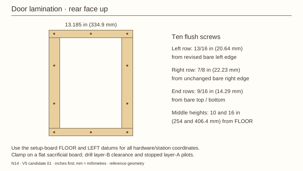
BL → DBL
3.4075 / 1.8125 / 7.5 in 86.55 / 46.04 / 190.50 mm
−Y · 1 in (25.4 mm)
J150
BL → DBL
3.4075 / 1.8125 / 11.5 in 86.55 / 46.04 / 292.10 mm
−Y · 1 in (25.4 mm)
J151
BL → DBL
3.4075 / 1.8125 / 15.5 in 86.55 / 46.04 / 393.70 mm
−Y · 1 in (25.4 mm)
J154
BL → DBL
3.4075 / 1.8125 / 19.5 in 86.55 / 46.04 / 495.30 mm
−Y · 1 in (25.4 mm)
J155
BR → DBR
14.53 / 1.8125 / 7.5 in 369.06 / 46.04 / 190.50 mm
−Y · 1 in (25.4 mm)
J156
BR → DBR
14.53 / 1.8125 / 11.5 in 369.06 / 46.04 / 292.10 mm
−Y · 1 in (25.4 mm)
J157
BR → DBR
14.53 / 1.8125 / 15.5 in 369.06 / 46.04 / 393.70 mm
−Y · 1 in (25.4 mm)
J160
BR → DBR
14.53 / 1.8125 / 19.5 in 369.06 / 46.04 / 495.30 mm
−Y · 1 in (25.4 mm)
J161
BB → DBB
6 / 1.8125 / 5.43875 in 152.40 / 46.04 / 138.14 mm
−Y · 1 in (25.4 mm)
J162
BB → DBB
12 / 1.8125 / 5.43875 in 304.80 / 46.04 / 138.14 mm
−Y · 1 in (25.4 mm)
Fastener stations · 145–162
X / Y / Z from outside LEFT / FRONT / FLOOR UNDERSIDE. Start coordinates include the veneer entry shift where applicable. Trace actual hardware only after its accepted sample fit.
ID
Through → receiver
Start X / Y / Z
Direction / nominal length
J163
BT → DBT
6 / 1.8125 / 21.06125 in 152.40 / 46.04 / 534.96 mm
−Y · 1 in (25.4 mm)
J164
BT → DBT
12 / 1.8125 / 21.06125 in 304.80 / 46.04 / 534.96 mm
−Y · 1 in (25.4 mm)
HP1
hardware → FAR
16.1 / -0.03875 / 13 in 408.94 / -0.98 / 330.20 mm
+Y · 5/8 in (15.88 mm)
HP2
hardware → FAR
16.47 / -0.03875 / 13.5 in 418.34 / -0.98 / 342.90 mm
+Y · 5/8 in (15.88 mm)
HP3
hardware → FAR
16.57 / -0.03875 / 12.5 in 420.88 / -0.98 / 317.50 mm
+Y · 5/8 in (15.88 mm)
ST1
hardware → DAR
14.22 / -0.03875 / 12.44 in 361.19 / -0.98 / 315.98 mm
+Y · 5/8 in (15.88 mm)
ST2
hardware → DAR
15.34 / -0.03875 / 12.44 in 389.64 / -0.98 / 315.98 mm
+Y · 5/8 in (15.88 mm)
ST3
hardware → DAR
14.22 / -0.03875 / 13.56 in 361.19 / -0.98 / 344.42 mm
+Y · 5/8 in (15.88 mm)
ST4
hardware → DAR
15.34 / -0.03875 / 13.56 in 389.64 / -0.98 / 344.42 mm
+Y · 5/8 in (15.88 mm)
H1F1
hardware → FAL
1.5625 / -0.04875 / 8.3425 in 39.69 / -1.24 / 211.90 mm
+Y · 1 in (25.4 mm)
H1F2
hardware → FAL
1.3425 / -0.04875 / 9.3125 in 34.10 / -1.24 / 236.54 mm
+Y · 1 in (25.4 mm)
H1F3
hardware → FAL
1.5625 / -0.04875 / 10.2825 in 39.69 / -1.24 / 261.18 mm
+Y · 1 in (25.4 mm)
H1D1
hardware → DAL
3.0025 / -0.04875 / 8.3425 in 76.26 / -1.24 / 211.90 mm
+Y · 1 in (25.4 mm)
H1D2
hardware → DAL
3.2225 / -0.04875 / 9.3125 in 81.85 / -1.24 / 236.54 mm
+Y · 1 in (25.4 mm)
H1D3
hardware → DAL
3.0025 / -0.04875 / 10.2825 in 76.26 / -1.24 / 261.18 mm
+Y · 1 in (25.4 mm)
H2F1
hardware → FAL
1.5625 / -0.04875 / 15.8425 in 39.69 / -1.24 / 402.40 mm
+Y · 1 in (25.4 mm)
H2F2
hardware → FAL
1.3425 / -0.04875 / 16.8125 in 34.10 / -1.24 / 427.04 mm
+Y · 1 in (25.4 mm)
H2F3
hardware → FAL
1.5625 / -0.04875 / 17.7825 in 39.69 / -1.24 / 451.68 mm
+Y · 1 in (25.4 mm)
Fastener stations · 163–180
X / Y / Z from outside LEFT / FRONT / FLOOR UNDERSIDE. Start coordinates include the veneer entry shift where applicable. Trace actual hardware only after its accepted sample fit.
ID
Through → receiver
Start X / Y / Z
Direction / nominal length
H2D1
hardware → DAL
3.0025 / -0.04875 / 15.8425 in 76.26 / -1.24 / 402.40 mm
+Y · 1 in (25.4 mm)
H2D2
hardware → DAL
3.2225 / -0.04875 / 16.8125 in 81.85 / -1.24 / 427.04 mm
+Y · 1 in (25.4 mm)
H2D3
hardware → DAL
3.0025 / -0.04875 / 17.7825 in 76.26 / -1.24 / 451.68 mm
+Y · 1 in (25.4 mm)
J201
LCL → P03L
1.175 / 14.325 / 3.97 in 29.85 / 363.85 / 100.84 mm
−X · 1 in (25.4 mm)
J202
LCL → P03L
1.175 / 10.45167 / 3.97 in 29.85 / 265.47 / 100.84 mm
−X · 1 in (25.4 mm)
J203
LCL → P03L
1.175 / 6.57833 / 3.97 in 29.85 / 167.09 / 100.84 mm
−X · 1 in (25.4 mm)
J204
LCL → P03L
1.175 / 2.705 / 3.97 in 29.85 / 68.71 / 100.84 mm
−X · 1 in (25.4 mm)
J205
LCR → P03R
16.825 / 14.325 / 3.97 in 427.35 / 363.85 / 100.84 mm
+X · 1 in (25.4 mm)
J206
LCR → P03R
16.825 / 10.45167 / 3.97 in 427.35 / 265.47 / 100.84 mm
+X · 1 in (25.4 mm)
J207
LCR → P03R
16.825 / 6.57833 / 3.97 in 427.35 / 167.09 / 100.84 mm
+X · 1 in (25.4 mm)
J208
LCR → P03R
16.825 / 2.705 / 3.97 in 427.35 / 68.71 / 100.84 mm
+X · 1 in (25.4 mm)
J209
LCF → FBB
2.8 / 1.705 / 3.97 in 71.12 / 43.31 / 100.84 mm
−Y · 1 in (25.4 mm)
J210
LCF → FBB
6.93333 / 1.705 / 3.97 in 176.11 / 43.31 / 100.84 mm
−Y · 1 in (25.4 mm)
J211
LCF → FBB
11.06667 / 1.705 / 3.97 in 281.09 / 43.31 / 100.84 mm
−Y · 1 in (25.4 mm)
J212
LCF → FBB
15.2 / 1.705 / 3.97 in 386.08 / 43.31 / 100.84 mm
−Y · 1 in (25.4 mm)
J213
LCB → P04
3.3 / 16.825 / 3.97 in 83.82 / 427.35 / 100.84 mm
+Y · 1 in (25.4 mm)
J214
LCB → P04
7.1 / 16.825 / 3.97 in 180.34 / 427.35 / 100.84 mm
+Y · 1 in (25.4 mm)
J215
LCB → P04
10.9 / 16.825 / 3.97 in 276.86 / 427.35 / 100.84 mm
+Y · 1 in (25.4 mm)
Fastener stations · 181–183
X / Y / Z from outside LEFT / FRONT / FLOOR UNDERSIDE. Start coordinates include the veneer entry shift where applicable. Trace actual hardware only after its accepted sample fit.
ID
Through → receiver
Start X / Y / Z
Direction / nominal length
J216
LCB → P04
14.7 / 16.825 / 3.97 in 373.38 / 427.35 / 100.84 mm
+Y · 1 in (25.4 mm)
J217
LCPL → CLV
1.47 / 15.325 / 3.97 in 37.34 / 389.26 / 100.84 mm
+Y · 1 in (25.4 mm)
J218
LCPR → CRV
16.53 / 15.325 / 3.97 in 419.86 / 389.26 / 100.84 mm
+Y · 1 in (25.4 mm)
Openings and service cuts
Cut / part
Lower corner X / Y / Z
Size X × Y × Z
CUT-left-inlet / P03L
0 in (0 mm) / 6 in (152.4 mm) / 5.72 in (145.29 mm)
0.72 in (18.29 mm) × 6 in (152.4 mm) × 2 in (50.8 mm)
CUT-right-inlet / P03R
17.28 in (438.91 mm) / 6 in (152.4 mm) / 5.72 in (145.29 mm)
0.72 in (18.29 mm) × 6 in (152.4 mm) × 2 in (50.8 mm)
CUT-roof / P02
3 in (76.2 mm) / 4 in (101.6 mm) / 23.28 in (591.31 mm)
12 in (304.8 mm) × 10 in (254 mm) × 0.72 in (18.29 mm)
CUT-restraint / P04
6 in (152.4 mm) / 17.28 in (438.91 mm) / 21.905 in (556.39 mm)
6 in (152.4 mm) × 0.72 in (18.29 mm) × 1 1/4 in (31.75 mm)
CUT-hinge-seat-7.8125 / FAL
1.0325 in (26.23 mm) / 0 in (0 mm) / 7 13/16 in (198.44 mm)
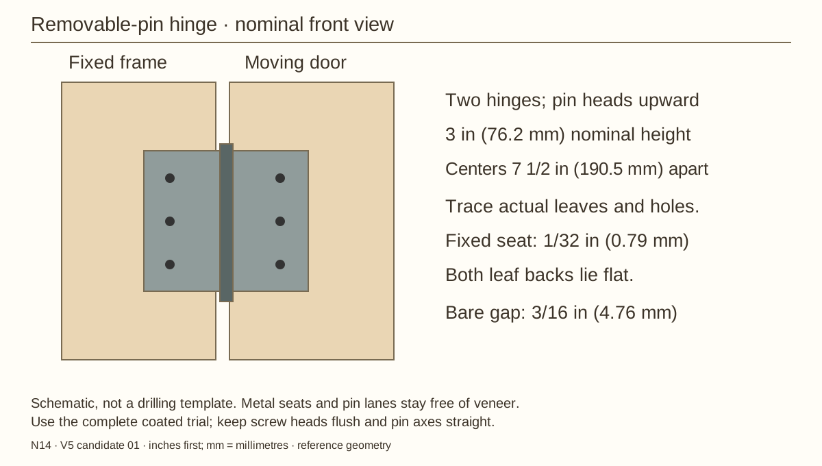
1 3/16 in (30.16 mm) × 1/32 in (0.79 mm) × 3 in (76.2 mm)
CUT-hinge-seat-15.3125 / FAL
1.0325 in (26.23 mm) / 0 in (0 mm) / 15 5/16 in (388.94 mm)
1 3/16 in (30.16 mm) × 1/32 in (0.79 mm) × 3 in (76.2 mm)
CUT-pin-lane-10.8125 / FAL
2.0325 in (51.63 mm) / 0 in (0 mm) / 10 13/16 in (274.64 mm)
3/16 in (4.76 mm) × 1/16 in (1.59 mm) × 3 3/8 in (85.72 mm)
CUT-pin-lane-18.3125 / FAL
2.0325 in (51.63 mm) / 0 in (0 mm) / 18 5/16 in (465.14 mm)
3/16 in (4.76 mm) × 1/16 in (1.59 mm) × 3 3/8 in (85.72 mm)
CUT-hasp-seat / FAR
15.79 in (401.07 mm) / 0 in (0 mm) / 12 1/4 in (311.15 mm)
1.28 in (32.51 mm) × 1/32 in (0.79 mm) × 1 1/2 in (38.1 mm)
Coordinates use the same outside assembly datums. Field-transfer hinge/hasp outlines from actual accepted hardware. The exact veneer schedule adds edge strips inside the openings; its cutouts preserve metal seats, pin lanes and upper washer bearing planes.
BUILD THE ENCLOSURE · 1 OF 47
1. Prove the veneer system before final cuts
Parts: Chosen veneer; trial board and plywood offcuts
Before you begin: This conditional veneer system is not cleared for fabrication until these inputs are resolved.
Prove the veneer system before final cuts
Choose maple, white oak or walnut with the exact factory-applied 3M pressure-sensitive adhesive (PSA) backing. A finish-picture choice alone is not a product approval. Read the supplier instructions and get confirmation for presealed plywood and pine, one-sided door/panel balance, coated edges, cleaning and intended humidity.
Use the fourth pine board for full-height hinge and door-edge trials; also reserve a panel offcut for a wide bond/flatness trial. Apply the complete proposed preseal, veneer, adhesive and topcoat system. Measure the cured stack with a caliper at several points; maximum 0.046 in (1.17 mm). The picture model uses 0.0305 in (0.77 mm).
Obtain the actual adhesive pressure/dwell instructions and acceptance criteria. Check bond, lifting edges and flatness through the proposed exposure. Do not invent a dwell time or proceed when supplier guidance or the full-size trial is unresolved.
Check before continuing: Record product, backing, total cured thickness, application/dwell instructions and accepted balance trial.
Parts: FAL and DAL trial layers; McMaster 1798A21 pair
Before you begin: Use full-height matching wood. Support the moving trial leaf.
Set up the full-height hinge trial
Use one pair of McMaster 1798A21 removable-pin surface hinges and twelve Hillman 35053 #8 × 1 in (25.4 mm) flat-head screws from the existing box. Set aside the hinge package screws. Drawing: 3 in (76.2 mm) high, 2 1/2 in (63.5 mm) open, leaf about 5/64 in (1.98 mm) thick, 3/8 in (9.52 mm) barrel and 1/4 in (6.35 mm) pin.
On full-height matching frame/door offcuts, reproduce the 3/16 in (4.76 mm) bare hinge gap and 1/32 in (0.79 mm) door setback. Trace the actual fixed leaves and rout/chisel flat 1/32 in (0.79 mm)-deep face seats. Clamp both leaf backs on the same plane, barrels outside, pin heads up, axes straight and centres 7 1/2 in (190.5 mm) apart. No edge mortises. Add the selected cured veneer system to both trial edges. Leave the traced metal seats and pin lanes uncovered by veneer.
Check before continuing: Both hinge backs bear flat; axes straight and centers 7 1/2 in (190.5 mm) apart.
Transfer actual holes. Start with 7/64 in (2.78 mm) pine pilots, checking actual roots and a trial drive. Stop at 31/32 in (24.61 mm) from the seated wood face including the point. Require flush heads without metal alteration, at least 1/4 in (6.35 mm) back cover and no splitting/stripping. Check this on the test assembly before drilling the door.
Finish the trial mating wood, fully cure and refit. Require free closed-to-95° movement, no leaf/head/wood contact and at least 1/16 in (1.59 mm) finished perimeter running clearance and 1/32 in (0.79 mm) retainer-to-stop clearance. Remove upper pin then lower with the leaf supported; reproduce the pin-head clearance lanes and the 3 1/8 in (79.38 mm) upward-then-forward removal path in the hinge operations on the trial. The nominal barrel-to-barrel gap is 4 1/2 in (114.3 mm). Correct wrong hardware, rocking seats or proud heads before final cuts.
Check before continuing: Full 0–95° swing, required clearances and upper-then-lower pin removal pass on fully cured trials.
Parts: FAR/DAR trial pieces; National N305-979; seven Everbilt 825391 screws
Prove the keyless latch on scraps
Receive one National Hardware N305-979 swivel-staple hasp and seven separate Everbilt 825391 #10 × 5/8 in (15.88 mm) flat-head screws. Set aside any longer supplied screws. On matching offcuts, reproduce a 1 1/2 in (38.1 mm) fixed upright beside a 1 3/4 in (44.45 mm) latch-side moving upright, with a 3/16 in (4.76 mm) gap and the door face set back 1/32 in (0.79 mm).
Put the narrow hinged base on the fixed upright and the square swivel plate on the wider door upright. Trace and cut a flat 1/32 in (0.79 mm) face seat under the fixed base only, bringing the two mounting backs onto the same plane. Both entire plates must bear on wood. Use the actual parts as templates.
Keep actual hole centres at least 1/4 in (6.35 mm) from wood edges and other screw shafts. Test the #10 root-matched pilot, screw head seating and stopped depth on the scrap; leave at least 1/2 in (12.7 mm) wood behind the tips. Do not alter metal holes or countersinks.
Turn the swivel to align with the slot, lift the flap clear, then open the door scrap. Close the flap and turn the swivel across the slot to secure it by hand. Repeat on fully cured scrap. No key is needed; a padlock is optional secondary security and is not included.
Check before continuing: Coated hinge/hasp trials, complete restraint-kit access and cured glazing test sample accepted before dependent work.
Select one Hillman 9976524 kit. Bench-assemble its furniture bracket, cable eye, clevis and cotter. Make a 6 in (152.4 mm) × 1 1/4 in (31.75 mm) window in an offcut of the actual plywood clamped over 1 1/2 in (38.1 mm) square pine. This reproduces the exterior recess before any final cut.
Set the bracket long axis horizontally. Its entire base must fit a 5 1/2 in (139.7 mm) × 1 in (25.4 mm) band centred on the window; screw centres must stay at least 3/8 in (9.52 mm) from the pine’s top/bottom edges. Transfer actual holes and trial the supplied two 5/8 in (15.88 mm) furniture screws with root-matched pilots, stopped at 5/8 in (15.88 mm) maximum including the point. Pine beyond each tip remains at least 7/8 in (22.22 mm).
Check before continuing: Bracket fits the bounded window and screws enter solid pine.
Parts: Complete trial bracket, cable and retainers
Rehearse restraint access and removal
Require flat full bearing, firm screws and straight driver access to both heads through the window. The preassembled bracket must enter/leave the recess. Cable, clevis and cotter must clear its edges; retain at least 1/8 in (3.17 mm) cable clearance through the intended route. Prove this before cutting P04.
For service, support the shell, release the wall end, remove both accessible furniture screws and bring the bracket outside before withdrawing its clevis. Pin withdrawal inside the recess is not required. If the exact actual kit cannot pass this scrap fit, correct orientation/identity and obtain its supported solid-frame fit before cutting; do not enlarge the window arbitrarily.
Check before continuing: Driver, cable and complete bracket fit without enlarging the specified opening.
Parts: Actual acrylic, EPDM cushions, Q spacer, B cap and door offcut
Before you begin: Finish the sample exactly as the final pane pocket.
Build a glazing test sample
Before cutting final Q spacers or gluing them to the door, make a small complete glazing test sample from the actual pane, plain EPDM, door offcut, spacer and cap. Start with a 5/16 in (7.94 mm) spacer. Use the same glue, coating surfaces and full cure as the finished door.
Measure the finished test pocket after the coating cures. Start with 5/16 in (7.94 mm) spacers, the actual acrylic sold as 0.22 in (5.59 mm) thick, and one 1/16 in (1.59 mm) cushion on each pane face. The cushions compress as the caps seat against the wood. Judge the fit by the flat, quiet pane and free edge movement in the next step; do not use screw force to bend the pane.
Check before continuing: Record the fully cured pocket and actual pane/cushion thickness.
Required wait: Complete the glue and coating waits before judging the fit.
Hand-seat the cap on its hard wood lands. The actual pane must stay flat, quiet and free to move at its edges. First correct wrong materials, overlapping strips, proud fasteners or uneven lands. If it still bows or rattles, do not commit the spacer depth: obtain the cushion/pane maker’s fitting advice and prove the corrected test sample. Never solve it by extra screw force.
Record measured pane thickness, strip thickness, cured pocket and the accepted spacer setting on a marked measuring strip. Retain the test sample for final assembly. This trial comes before the pane-retainer operations and before final spacer thicknessing.
Check before continuing: Cap rests on hard wood lands; pane remains flat, quiet and free at its edges.
Parts: Three production pine boards; fourth trial board; plywood
Before you begin: Follow the planer’s minimum feed size; do not feed short finished strips.
Prepare the wide stock
Measure the actual plywood thickness at its corners and centre. It is sold as nominal 3/4 in (19.05 mm); use the actual offcuts to fit the joining parts. Allow 1/4 in (6.35 mm) to square each board end and 1/8 in (3.17 mm) for each saw cut. Keep the blade on the waste side of the line.
Use one flat 3/4 in (19.05 mm) × 5 1/2 in (139.7 mm) × 96 in (2438.4 mm) pine board for the fixed frame and one for the door. Keep each board wide and long while planing: 5/8 in (15.88 mm) for fixed frame, 39/64 in (15.48 mm) for door. The door rear stays aligned with the stops; its front face sits 1/32 in (0.79 mm) behind the fixed-frame front. Complete the actual hinge, keyless hasp and restraint trials in the receiving trials before dependent seats, windows or final holes. Reserve a fourth matching board for the full-height hinge/veneer trial, hasp and glazing samples.
Board 3 wide blanks: 28 in (711.2 mm) at 3/4 in (19.05 mm) thick for screen strips and S01; 16 in (406.4 mm) at the test sample-proven spacer thickness (nominally 5/16 in (7.94 mm)) for Q spacers; 15 in (381 mm) at 1/4 in (6.35 mm) for B caps; 12 1/2 in (317.5 mm) at 1/2 in (12.7 mm) for S02. Follow planer minimum feed length; never feed short or narrow finished strips. Rip only after thicknessing.
Check before continuing: Stock received, marked and thicknessed before narrow strips are cut.
From board 3, reserve an 18 in (457.2 mm) long blank for the six liner clamps. Keep it 5 1/2 in (139.7 mm) wide while planing it to 3/8 in (9.52 mm) thick. Cut four 1/2 in (12.7 mm) wide strips, allowing 1/8 in (3.17 mm) for each saw cut. Strip 1: LCF about 16 7/16 in (417.51 mm). Strips 2 and 3: one LCL/LCR about 13 5/8 in (346.07 mm) and one LCPL/LCPR about 1 3/8 in (34.92 mm) from each. Strip 4: LCB about 13 7/16 in (341.31 mm). Leave the cut lines and trim to the actual lined corners. Drill the short upright clamps while attached to longer stock, then cut them free over backing.
Cut the two square-pine boards using the labelled lengths under Cut list and stock allocation. Keep matching parts together. Leave the four cross supports 14 in (355.6 mm) long until you can mark their finished length from the assembled gap. Retain offcuts for screw and finish tests.
Check before continuing: Leave cross supports as 14 in (355.6 mm) blanks until the assembled gap can be marked.
Parts: P01 floor, P02 roof, P03L/P03R walls, P04 back
Before you begin: Support both the workpiece and waste; keep the blade on the waste side.
Cut the walls and side inlets
Cut the floor and roof 18 in (457.2 mm) square. Start each side at 18 in (457.2 mm) deep × about 22 9/16 in (573.09 mm) high, and the back at about 16 9/16 in (420.69 mm) wide × 22 9/16 in (573.09 mm) high. Fit the sides between the actual floor and roof within the 24 in (609.6 mm) overall height; fit the back between the sides. Label both sides and match them using one stop or marked measuring strip.
On each side, mark 6 in (152.4 mm) and 12 in (304.8 mm) from the front edge, then 5 in (127 mm) and 7 in (177.8 mm) from its lower cut edge. Join these marks for a 6 in (152.4 mm) × 2 in (50.8 mm) inlet. Keep substrate at or below 3 in (76.2 mm) above the bare plywood floor reference edge, leaving 2 in (50.8 mm) beneath these inlets and 1/2 in (12.7 mm) of liner above the fill.
Check before continuing: Matched wall heights; two inlets referenced from the side-panel lower edges.
Before you begin: The floor stays solid. The restraint trial must pass before P04 is cut.
Cut the roof and backed rear window
On P02, mark 3 in (76.2 mm) and 15 in (381 mm) from its left edge and 4 in (101.6 mm) and 14 in (355.6 mm) from its front edge. This makes the 12 in (304.8 mm) × 10 in (254 mm) roof opening. Keep P01 solid. Clamp panels flat on sacrificial support, drill starter holes inside waste, cut to the lines and smooth the edges.
After the complete restraint-kit scrap trial passes, mark its 6 in (152.4 mm) × 1 1/4 in (31.75 mm) rear window centred across P04. Its top is 1/8 in (3.17 mm) below the back-panel top edge; its bottom is 1 3/8 in (34.92 mm) below that edge. Cut only the plywood. The later CBT wood support remains continuous behind the entire window, with 1/8 in (3.17 mm) overlap above and below.
Check before continuing: Roof opening and rear access window match their named datums.
Dry-lay both layers on a flat bench. Layer A has full-height uprights; layer B has full-width rails. Transfer fitted lengths from the matching panels and members; align the outer perimeter and opening without rounding a mating cut.
For the station drawing, place actual plywood-thickness gauges beyond the frame’s bottom and left edges. Their outer faces represent the cabinet floor and side reference edges. Mark from those faces where named.
Spread Titebond III on bare mating faces and clamp square. Apply above 47°F (8.3°C); at 70°F (21.1°C) and 50% relative humidity (RH), allow 8–10 minutes open time and 20–25 minutes total assembly time. Follow the label’s clamp instructions; do not stress the joint for at least 24 hours.
From layer B, drill 11/64 in (4.37 mm) clearance through that layer only, then a stopped 7/64 in (2.78 mm) pilot 7/16 in (11.11 mm) into A. Test on an offcut stack. Drive heads flush without burying them; nominal engagement is 3/8 in (9.52 mm) with 1/4 in (6.35 mm) tip cover.
Check before continuing: Flat square layers; staggered joints; flush heads and no exposed tips.
Required wait: Do not stress the glue-up for at least 24 hours; follow actual clamp instructions.
Before you begin: Keep the glazing aperture and hardware bearing zones intact.
Fit and glue the thinner door
Lay both door layers on a flat bench. The reference bare door is 13.185 in (334.9 mm) wide by 16.685 in (423.8 mm) high. Fit to the actual frame opening with 3/16 in (4.76 mm) raw gaps on ALL four sides. Use two 39/64 in (15.48 mm) layers, with a total 1 7/32 in (30.96 mm) core thickness and the front set back 1/32 in (0.79 mm). Reduce only the hinge-side, top and bottom edges from the original blank; keep the full 1 3/4 in (44.45 mm) latch-side upright for the swivel plate. Keep the original inner glazing aperture. Match the layers before gluing.
Apply Titebond III to bare mating faces and clamp square. Apply above 47°F (8.3°C). At 70°F (21.1°C)/50% relative humidity (RH), open time is 8–10 minutes and total assembly time 20–25 minutes. Follow label clamping instructions; do not stress the bond for at least 24 hours.
Check before continuing: Bare 3/16 in (4.76 mm) gaps all around; latch-side upright remains full width.
Required wait: Do not stress the glued assembly for at least 24 hours.
From the revised bare door left edge, mark the left screw row 13/16 in (20.64 mm) inward. Mark the right row 7/8 in (22.22 mm) inward from the unchanged latch edge. Both rows have end screws 9/16 in (14.29 mm) from the top/bottom; middle screws are 10 in (254 mm) and 16 in (406.4 mm) above the floor-underside datum. Add one centered screw to each end rail at the same end-screw heights. Ten screws total. Use the full-size setup-board datums and exact station drawing; do not measure these from the veneer edge.
From layer B, drill 11/64 in (4.37 mm) clearance through B only, then a stopped 7/64 in (2.78 mm) pilot 7/16 in (11.11 mm) into A. Use #8 × 1 in (25.4 mm) flat heads, flush. Nominal engagement is 25/64 in (9.92 mm); tip cover is 7/32 in (5.56 mm). Test the actual screw and countersink on a matched offcut stack first.
Check before continuing: Ten reference stations retain back cover and avoid later hardware.
Before you begin: Clamp panels flat before drilling. Transfer the actual supports before marking pilots.
Fit the side and rear wood supports
Clamp each side inner face up. The top and bottom wood supports begin 1 1/4 in (31.75 mm) behind its front edge and finish flush with its top and bottom. Fit the rear upright between them. Use an offcut of the actual back plywood to set it forward of the rear edge; this reserves the back-panel rebate.
Start each back cross wood support as a 14 in (355.6 mm) blank. Place 1 1/2 in (38.1 mm) square offcuts flush with the back panel’s side edges; mark and trim each blank to the gap between them. Fit the cross wood supports flush with the top and bottom.
Use the actual plywood as a thickness gauge: clamp an offcut against the lower panel edge for the floor reference edge, and against the back panel’s left edge for the side reference edge. Measure from each gauge’s outer face. Mark the rows in the station drawing. Drill 11/64 in (4.37 mm) clearance through plywood only, then a stopped 7/64 in (2.78 mm) pilot 1 1/8 in (28.57 mm) into pine. Test the actual screws on a matching offcut.
Drive screws until the flat heads are flush. Do not bury them. Keep the mating panel labels; the six back-to-upright screws are fitted later with the shell clamped square.
Check before continuing: Solid supports seated; side inlets and restraint recess remain clear.
Before you begin: Use a helper and a fully supporting bench; do not rely on loose panels to stand.
Dry-assemble the case
On a flat support, stand both prepared sides on P01. Fit the back between them, with its rear face flush to the side rear edges. Have a helper hold the panels while clamps keep the shell square.
Fit the laminated front frame between the sides, its front face flush with their front edges. Fit CFB and CFT between the side wood supports directly behind the frame. Use 14 in (355.6 mm) blanks marked to the actual gap; hold these cross wood supports clamped until the floor and roof ties are fitted.
Mark the back and side-front rows in the station drawing. All heights here are measured from the assembled floor’s underside. This keeps the original stagger between shell and layer screws.
Drill 11/64 in (4.37 mm) clearance through plywood only and a stopped 7/64 in (2.78 mm) pilot 1 1/8 in (28.57 mm) into pine. Check the actual #8 screws on an offcut; countersink and drive only to flush. Keep the shell supported and clamped for the next step.
Check before continuing: Supported square shell; front cross supports remain clamped.
Before you begin: Lay the clamped case on broad padded support to reach underside screws.
Tie the floor and removable roof
Transfer the fitted side- and rear-wood support centre lines onto each matching floor/roof panel before closing the shell. Mark from actual members; do not round a calculated panel offset.
Lay out the four rows in the station drawing on each panel. Measurements along the rows start at the cabinet’s outside left or front edge. Use the solid floor pattern on P01; all P02 holes stay outside its roof opening.
With a helper, support the clamped shell securely on a broad padded surface to access the underside. Never balance it on a narrow edge. Drill and fasten P01, then fit and fasten P02 from above.
Use 11/64 in (4.37 mm) plywood clearance and a stopped 7/64 in (2.78 mm) pine pilot 1 1/8 in (28.57 mm) deep, checked on an offcut. Drive heads flush. Recheck diagonals before final tightening. Retain matching labels and holes for later disassembly and coating.
Check before continuing: Floor and roof seat; both diagonals agree within 1/16 in (1.59 mm); roof remains removable.
Before you begin: Size the pane from the bare aperture; no screw may enter it.
Fit the pane pocket and caps
Start the acrylic pane at about 10 1/2 in (266.7 mm) × 15 1/16 in (382.59 mm), sold as 0.22 in (5.59 mm) thick. Fit it to the bare door opening before veneer: add 3/4 in (19.05 mm) to the opening width and height, giving 3/8 in (9.52 mm) bearing at each edge. Keep 1/8 in (3.17 mm) space around the pane inside its pocket and 1/4 in (6.35 mm) cap overlap. Use the spacer thickness proved by the coated test sample in the receiving trials. Repeat that fit before gluing the spacers to bare door wood with Titebond III. Keep glue out of the pocket and leave 1/16 in (1.59 mm) between the retaining-strip ends and door stops. The veneer window strips reduce the visible opening only; do not size the pane from that smaller finished view.
Clamp the caps against the hard Q lands without the pane. Mark side screws on the fitted Q centre lines: floor-reference edge heights 7 1/2 in (190.5 mm), 11 1/2 in (292.1 mm), 15 1/2 in (393.7 mm), 19 1/2 in (495.3 mm). Mark two screws on each end-spacer centre line at 6 in (152.4 mm) and 12 in (304.8 mm) from the cabinet-left reference edge; use the transferred cabinet-left line on the setup board. Twelve screws total.
Check before continuing: Pocket and overlap match the accepted coupon and actual pane.
Required wait: Allow glued spacers at least 24 hours without stress before machining.
Drill 1/8 in (3.17 mm) clearance through each cap and spacer only; use a receiving pilot matched to the actual #4 screw root on a door offcut. Stop at 1/2 in (12.7 mm) maximum into door wood including the point. Use #4 × 1 in (25.4 mm) flat heads flush, not buried: nominal door engagement is 7/16 in (11.11 mm). No screw enters the pane. Label and remove caps for coating.
Cut plain ethylene propylene diene monomer (EPDM) cushions for both pane faces. Each ring needs two end strips about 10 1/2 in (266.7 mm) long. The front ring has two side strips about 14 5/16 in (363.54 mm) long and is 3/8 in (9.52 mm) wide. The rear ring has two side strips about 14 9/16 in (369.89 mm) long and is 1/4 in (6.35 mm) wide. Trim to the actual pane, butt the corners without overlap, and label all eight pieces. One 120 in (3048 mm) strip covers the approximately 100 in (2540 mm) total. No adhesive touches the acrylic. Install after full finish cure.
Check before continuing: Depth stops set; cap screws remain in wood; eight strips labeled.
Centre the 10 in (254 mm) lower stop across the fixed frame. Set its top 1/2 in (12.7 mm) above the lower front rail’s top edge; half of its 1 in (25.4 mm) height overlaps the rail. Clamp its front face against the back of FBB.
Centre the upper stop across the frame with its top face against CFT’s underside. Its front face aligns with the back of the fixed frame. It fastens upward into CFT, not into the front upper rail.
Mark each stop 1 in (25.4 mm), 5 in (127 mm) and 9 in (228.6 mm) from its left end. For S01, drill toward the front through its back face, 1/4 in (6.35 mm) above its lower edge. For S02, drill upward through its underside at the centre of its 3/4 in (19.05 mm) depth.
Drill 11/64 in (4.37 mm) clearance through the stop only. Test pilot and head seating on matching offcuts: nominal screw engagement is 1/2 in (12.7 mm) in FBB and 3/4 in (19.05 mm) in CFT. Keep pilots within the receivers; drive heads flush. Repeat final closing checks after the hardware and glazing fitting steps.
Check before continuing: Stops seat firmly and clear the removable glazing caps.
Before you begin: Support the enclosure on its back; support the door separately.
Block the door and cut pin lanes
Lay the shell on its back on continuous padded support. Block the door against its stops. Use 3/16 in (4.76 mm) bare spacers on all four sides. Mark hinge centres 9 5/16 in (236.54 mm) and 16 13/16 in (427.04 mm) above the floor underside. Position the actual hinges using the successful test assembly, with both pin axes straight and the barrels outside the wood.
Provide a pin-head clearance lane above each fixed hinge seat, on the opening edge of FAL: 3/16 in (4.76 mm) wide, 1/16 in (1.59 mm) deep and 3 3/8 in (85.72 mm) long, starting at the seat’s upper edge. The nominal lane starts are 10 13/16 in (274.64 mm) and 18 5/16 in (465.14 mm) above the floor underside. These shallow lanes clear the head during extraction; keep the remaining upright and hinge screw bearing intact. Cut on supported stock and ease the edges; coat and fully cure with the other wood in the coating operations. Repeat the actual pin trial; require at least 1/32 in (0.79 mm) finished clearance to wood. Mask these complete lanes during veneering. Veneer must not narrow the release path.
Check before continuing: Axes marked; full 3 3/8 in (85.72 mm) lanes preserved above each hinge.
Parts: McMaster pair; twelve specified hinge screws
Seat and fasten the actual hinges
Trace each actual fixed hinge leaf, centred on its marked hinge height. Cut its flat 1/32 in (0.79 mm) face seat using shallow supported passes. Keep the wood outside the traced outline except for the specified pin-clearance lanes. Lay both hinges flat and align their pins with a straightedge.
Transfer the holes from the actual hinges. Mark the rear frame-screw locations on the front so every new screw stays at least 1/4 in (6.35 mm) from another screw shaft. If holes conflict, lower both hinges together by no more than 1/8 in (3.17 mm), keeping their 7 1/2 in (190.5 mm) spacing and full wood support. Repeat the complete coated swing and pin-removal test. Do not raise the upper hinge toward the top frame.
Drill the proven stopped pilots and fit all twelve #8 × 1 in (25.4 mm) screws flush. Remove shims and test the supported swing. Correct squareness, seat flatness and pin alignment first. If only a wood edge contacts, remove the leaf and plane minimally; retain 1 1/2 in (38.1 mm) side uprights, glazing bearing, stop overlap and 1/4 in (6.35 mm) screw-edge distance. Refinish, fully cure and repeat the trial. Never bend hinges or enlarge metal holes. Preserve the complete latch-side edge and metal backing; this is not an edge to trim for clearance.
Check before continuing: Coated trial reproduced; no split wood, proud heads or hardware conflict.
Parts: Complete supported door and both hinge pins
Before you begin: Support the complete door. Never carry it by the pane.
Rehearse door removal with the roof on
Reserve 15 in (381 mm) in front plus the full swing sector. Keep the shell supported/restrained. To remove: turn the swivel and release the hasp, support the complete door, withdraw the upper pin 3 1/8 in (79.38 mm), just until its tip clears the upper knuckle, then move it forward into free space; repeat for the lower pin. Do not continue pulling either pin upward into the header. Confirm this path with the actual pin before final machining, then move it off the mating knuckles. Refit lower then upper pin with support. Never lift by acrylic. Repeat the full swing, latch and removal after full cure.
Check before continuing: Upper pin out first, then lower; lower pin in first when refitting.
Before you begin: Wear protection for cut wire. Machine recesses in long supported stock.
Capture both side screens
Centre each mesh blank over its 6 in (152.4 mm) × 2 in (50.8 mm) opening: overlap is 3/4 in (19.05 mm) on every side. File all clipped ends. The outer screen strip perimeter extends 1/4 in (6.35 mm) beyond each cut wire edge.
Route the panel-facing screen strip recess 1/8 in (3.17 mm) deep, following the mesh footprint plus 1/8 in (3.17 mm) around its perimeter. Leave a continuous 1/8 in (3.17 mm) outer land, including across corner joints. Route supported wide blanks before short final cut to lengths. The actual wire crossing plus finish must fit below the recess.
Clamp screen strips tight to the panel. Drill 11/64 in (4.37 mm) clearance through screen strips only. After an offcut test, stop the receiving plywood pilot at no more than 9/16 in (14.29 mm) including its point. Centre each screw in a mesh opening or clear wire locally inside the captured pocket; remove all clippings.
Drive heads flush, not buried. The nominal plywood engagement is 1/2 in (12.7 mm). Inspect every corner and outer land for trapped wire and exposed points. Mesh aperture still requires a separate animal/feeder suitability check.
Check before continuing: Wire edges fully enclosed; all lands bear; openings clear.
Work with the roof inside face up, keeping its left/front labels visible. Centre the 13 in (330.2 mm) × 11 1/2 in (292.1 mm) mesh on the 12 in (304.8 mm) × 10 in (254 mm) opening: 1/2 in (12.7 mm) overlap left/right, 3/4 in (19.05 mm) front/rear. File cut ends. Place the long screen strips at the front/rear of the opening and the 3/4 in (19.05 mm)-wide side screen strips between them.
Recess each panel-facing screen strip surface 1/8 in (3.17 mm) deep across the mesh footprint plus 1/8 in (3.17 mm) around its cut perimeter. Retain a continuous 1/8 in (3.17 mm) outer wood land. Work on supported wide stock before cutting small pieces. Received wire crossings plus coating must fit without holding those lands off the panel.
Before you begin: Clamp steel for drilling; deburr all faces. No load rating follows from this fit.
Fit the two steel support strips
Cut two 11 1/2 in (292.1 mm) lengths from the single 36 in (914.4 mm) steel bar. File and deburr them. Mark two 1/4 in (6.35 mm) bores along each width centreline, 1/4 in (6.35 mm) from each end; drill over backing and deburr both faces. These centres are 11 in (279.4 mm) apart.
Set the strip width centrelines 4 in (101.6 mm) and 8 1/2 in (215.9 mm) from the roof left edge; the ends are 3 1/4 in (82.55 mm) and 14 3/4 in (374.65 mm) from its front. Transfer their actual footprints to RF/RB. Recess those end footprints beneath the wire by the measured steel thickness so both strips touch the mesh underside. Measure the actual steel and crossed wires together to set the recess. Use actual material to set the recess, preserving full end support and more than 1/2 in (12.7 mm) wood beneath it.
Check before continuing: Actual strips contact mesh and retain more than 1/2 in (12.7 mm) wood below the end recesses.
Parts: Four bolts, eight washers, four nuts; fourteen wood screws
Before you begin: Check both corrected side rows before drilling. Keep all service heads exposed.
Bolt and screw the roof assembly
Clamp the fitted roof/screen strip/steel stack and transfer the four bolt centres: 4 in (101.6 mm) and 8 1/2 in (215.9 mm) from the left, each at 3 1/2 in (88.9 mm) and 14 1/2 in (368.3 mm) from the front. Remove the steel and mesh before drilling wood; drill 1/4 in (6.35 mm) clearance through roof and screen strips with backing. Align real mesh cells with the holes without trapped wire or loose clipped ends.
Fit each bolt from the roof top through a washer, plywood, mesh, steel and screen strip, then the second washer and Keps nut underneath. Seat the stack flat before tightening. All nut threads must engage, with no sharp or snagging tail. Do not crush the wood. This construction is a proposed support, not a tested load rating.
Install the fourteen roof-retainer wood screws from the exact station drawing. RL and RR side-retainer rows are 2 5/8 in (66.67 mm) and 15 3/8 in (390.52 mm) from the roof left edge; each has stations 5 1/2 in (139.7 mm), 8 1/2 in (215.9 mm), 11 1/2 in (292.1 mm) from the front. Each hole must lie over solid roof plywood, outside the opening. Use 11/64 in (4.37 mm) clearance through the retainer only and a root-tested plywood pilot stopped at 9/16 in (14.29 mm) maximum including the point. Seat the heads flush and keep wire clear of the bearing lands. Refit the roof with its existing shell holes; side retainers must clear the upper case supports.
Check before continuing: All side-retainer screws pass into solid roof plywood, outside its opening.
Block the door closed with the proven gaps. Mark a horizontal line 13 in (330.2 mm) above the floor underside. Centre the swivel plate on the door upright at that height, using the actual hardware from the test assembly. Keep the whole plate on wood and each hole at least 1/4 in (6.35 mm) from an edge or another screw.
Place the narrow hinged base on FAR and the square swivel plate on DAR. Close the flap over the swivel without pulling the door sideways. Trace the actual fixed base and cut its flat 1/32 in (0.79 mm) face seat. Do not cut outside its traced outline; use the tested hardware placement rather than measuring from the illustration.
Check all seven transferred holes against frame, door and glazing screws. Use the stopped pilot and screw-head fit proved in the receiving trials. Fit the three base screws into FAR and four swivel-plate screws into DAR, retaining at least 1/2 in (12.7 mm) rear cover. Hand-seat without crushing wood.
Turn the swivel, swing the flap fully away from the moving leaf and open through 90°. Close without pulling the leaf sideways. Turn the swivel across the closed slot to retain the flap. Repeat after finish cure. Use a separate handle grip on the wood rather than pulling on the pane or flap.
Check before continuing: Turn, release, open, close and secure by hand without pulling the door sideways.
Before you begin: The liner protects the damp basin; this finish is not an immersion coating.
Strip the dry fit and prepare for coating
Use Varathane Triple Thick satin brush-on, manufacturer 284473: Lowe’s item 9181732, seller model 284473-7482, sold as two quart cans per pack. Match the actual satin cans and label. This water-based polyurethane has a slight amber tone. It is selected for ordinary indoor, moderate-humidity service above the lined basin; the EPDM liner, not the finish, takes the damp substrate. Avoid standing water and fixture hotspots.
After successful dry fit, remove hardware, mesh, glazing and caps. Complete frame/door and Q-spacer glue-ups first; leave their bond faces bare. Sand clean dry wood from 120 through 220 grit, vacuum and wipe with a lint-free cloth. Coat disassembled screwed parts on all faces, edges and opening reveals; exclude bonded contacts.
Check before continuing: All glue-ups complete, sanding dust removed, matching parts retained.
Before you begin: Do not proceed without the accepted bond and panel-balance trial.
Preseal the veneer substrates
Keep screw holes, joints, metal bearing seats and pin lanes identified before coating. Preseal the porous veneer-bond surfaces with the supplier-approved system; keep glue bonds complete first.
The veneer supplier describes a minimum 24-hour sealer wait. This selected coating requires seven days for full cure at 70°F (21.1°C) and 50% relative humidity (RH); use the longer applicable requirement and any additional supplier dwell. Record conditions and extend for adverse conditions.
After acceptance, lightly scuff the cured bond faces with 120 grit as directed by the veneer supplier; clean without leaving contamination. Use only a cleaning method compatible with the selected coating and adhesive.
Check before continuing: Clean, flat approved bond faces; both product instructions satisfied.
Required wait: Full coating cure plus the supplier’s required adhesive preparation/dwell, whichever governs.
Use the grain-fixed veneer layout. Buy one 48 in (1219.2 mm) × 96 in (2438.4 mm) sheet of one selected species with the specified PSA backing. The allocation includes 53 pieces and three trial blanks, 1/4 in (6.35 mm) edge trim, 1/16 in (1.59 mm) cut separation and oversize trimming margins.
Lay out visible matching grain before cutting. Roof, floor-edge and horizontal rails run left-to-right; vertical walls/uprights run top-to-bottom. Mark each V-part and its parent on the backing. Keep the opening waste for repair coupons.
Cut separate flat face and edge strips. Do not bend veneer around the sharp plywood edge. Work on a cutting board with a held straightedge and repeated shallow knife passes, hands outside the cutting path.
Check before continuing: Every face, roof, underside and exposed reveal has a labeled piece; grain follows the layout.
Parts: All V-part edge strips; actual metal templates
Before you begin: The bare metal seats will be covered by hardware. Do not cut into structural wood while trimming.
Veneer the edges and opening reveals
Apply the square edge and reveal strips before the broad faces. Bond each to its own panel only. Butt adjoining pieces cleanly; do not overlap stacks or bridge the removable roof joint.
Leave the complete fixed/moving hinge seats, hasp seats and pin-release lanes free of veneer. Keep the original wood-bearing planes under the four upper roof washers: trace each actual washer and trim the skin within that fully covered footprint.
Use the supplier’s firm scraper pressure from the center outward along the grain, with the part fully supported. Score and trim flush in shallow passes; ease sharp edges lightly without exposing a plywood stripe. Check every edge for lifting.
Check before continuing: No covered service joint or screw head; no veneer under metal bearing planes.
Parts: All outside V-parts; 72 shell screw stations
Before you begin: Hardware stays on the proved core bearing seats. Do not move it outward onto veneer.
Veneer the broad outside faces
Dry-position each labeled face before peeling the backing. Align the grain and leave the planned trimming margin. Press progressively from the center outward, covering the whole face with the specified firm scraper pressure.
Trim faces to the edge bands and openings without double layers. Keep each side, back, floor, roof and frame member independent; never veneer over a case seam or screw head.
Reopen every shell-screw station and test its actual head seat on an offcut. The same 1 3/4 in (44.45 mm) shell screws now seat on the veneer surface; the reference stack reduces wood engagement by 0.0305 in (0.77 mm). Keep heads accessible and flush. Do not bury hardware to hide it.
Check before continuing: Whole wooden exterior covered, including the roof and exposed edges; holes and removable joints stay open.
Required wait: Meet the adhesive maker’s actual dwell before topcoating or loading the bond; unresolved numeric dwell is a stop.
Parts: Varathane 284473 satin; final veneered parts
Before you begin: Ventilate and meet the current label’s temperature and humidity limits.
Apply the final coat and wait for full cure
Stir; do not shake. With ventilation, apply one uniform coat along the grain using a quality synthetic-bristle brush at 60–90°F (15.6–32.2°C) and below 85% relative humidity. This is a one-coat formulation; follow the actual product label. Follow the manufacturer’s stated application coverage; do not build up a thick coat. If another coat is needed, sand with 220 grit, allow the specified two-hour recoat interval at reference conditions, and add its area to the allowance.
The conservative rectangular wood area is 47.37 square feet (4.40 square metres). Adding a separate preseal/topcoat allowance for the veneer faces and another 15% contingency gives 74.49 square feet (6.92 square metres). At 50 square feet (4.65 square metres) per quart, the two-quart (1.89 litre) pack covers this one-coat schedule. Extra coats, balance layers or trials require a fresh allowance; it is not an immersion system.
Keep unoccupied until the final applied or repaired coat fully cures: seven days at 70°F (21.1°C) and 50% relative humidity with ventilation. The 48-hour light-use interval is not full cure. Record final-coat time and conditions; colder or adverse conditions require longer under manufacturer instructions. Do not replace full cure with touch-dry or odor checks. Inspect the coating for defects before reassembly.
Check before continuing: Application, repairs, coat count and full-cure deadline recorded.
Required wait: Seven days at 70°F (21.1°C) and 50% relative humidity (RH) after the last coat or repair; longer when conditions require.
Reassemble only after full cure. Check the actual finished gaps: at least 1/16 in (1.59 mm) around the moving door and at least 1/32 in (0.79 mm) between retaining strips and stops. Check all four gaps with the selected veneer in place. The measured complete veneer/adhesive/film stack must not exceed 0.046 in (1.17 mm) on any covered face. Avoid coating damage. Use the left steel-supported screen area only under the fixture conditions in the commissioning operations; keep heat off wood and glazing.
Check before continuing: At least 1/16 in (1.59 mm) at all moving perimeter edges and 1/32 in (0.79 mm) between caps and stops; stack at most 0.046 in (1.17 mm).
Parts: Labeled shell, mesh, Q/B parts, pane and cushions
Before you begin: Hand-tighten evenly. Extra screw force is not a fit adjustment.
Reassemble the shell and pane
After full cure, reassemble the labelled shell, mesh frames, supports and roof in the dry-fit order. Hand-seat screws in their original holes. Check square bearing and complete screen capture; keep the tall enclosure supported throughout.
Lay the cured door flat with its rear face upward. Fit the labelled front EPDM, centred pane and cap-side EPDM. Butt strip corners without overlap. Install the labelled caps and tighten the twelve screws evenly by hand until their hard wood lands seat.
Compare with the accepted test sample. Check both pane faces for bow, all edges for free expansion space, and carefully support/turn the door to check rattle. Correct misplaced strips or raised lands; never tighten against glass or acrylic, guess a shim, or machine a new pocket after assembly to force a fit.
Check before continuing: Pane flat and quiet; hard lands fully seated.
Before you begin: Any coating repair restarts the applicable cure wait.
Refit the door and inspect every edge
Support the complete leaf while refitting the hinge pins, lower then upper. Refit the keyless closure and test the full swing, hand release and roof-on pin service. Require at least 1/16 in (1.59 mm) actual cured perimeter running clearance and 1/32 in (0.79 mm) clearance from retainers to stops.
Inspect for exposed wire, sharp bolt tails, proud screws, cracked wood and finish damage. Refinish any repaired wood and repeat full cure before use. Keep all receiving and fit measurements with the completed guide.
Check before continuing: Repeat free swing, latch, roof-on pin removal and cured gap checks.
Parts: 36 in (914.4 mm) underlay square and 36 in (914.4 mm) EPDM square
Before you begin: Remove the roof; keep sharp edges and loose fasteners away from the liner.
Fold the uncut liner into the basin
After the finish fully cures, reassemble the shell and lift off the roof. Vacuum the inside and smooth sharp support edges. Mark the top of the bare plywood floor on all sides; use this same starting height for the fill, liner and clamp marks. Cut one 36 in (914.4 mm) square underlay and one matching 45 mil (0.045 in / 1.14 mm) EPDM liner. These blanks include room for the raised sides and corner folds. Keep all corners uncut.
Lay the underlay, then the EPDM, into the floor. Let both settle with slack over the bottom wood supports and against the walls. Fold each corner flat like a hospital corner and wrap the liner around the room faces of the two rear uprights. Never slit a corner or stretch the membrane over an edge.
Check before continuing: Slack folds cover the stepped supports and rear uprights; no cut corners.
Use the bare plywood floor reference edge for every height in this basin: maximum fill line 3 in (76.2 mm), liner upper edge 3 1/2 in (88.9 mm), and clamp screw centres 3 1/4 in (82.55 mm) above it. Trim only the upper margin after dry folding. The 1/2 in (12.7 mm)-high clamps span the 3 in (76.2 mm)–3 1/2 in (88.9 mm) band, above the fill; their tops are flush with the liner edge. The actual substrate depth is slightly less than 3 in (76.2 mm) because the liner and underlay occupy some height. Keep all substrate below the marked fill line, which leaves 2 in (50.8 mm) to the side-inlet bottoms. Do not measure these heights upward from the tops of the wood supports.
Check before continuing: Fill, clamp screw and liner-edge marks all start at the bare floor, not support tops.
Parts: LCL/LCR/LCF/LCB/LCPL/LCPR; eighteen #8 × 1 in (25.4 mm) screws
Before you begin: Fit to actual folds without stretching or pinching; keep every drill depth stopped.
Fasten the six removable liner clamps
Fit the six 3/8 in (9.52 mm) × 1/2 in (12.7 mm) clamps over the liner: LCL/LCR on the side walls, LCF against the front rail, LCB between the rear uprights, and LCPL/LCPR on their room faces. Preserve the uncut folds and fit clamp lengths to the actual lining stack without stretching or pinching it. Use the screw station schedule for all 18 #8 × 1 in (25.4 mm) screws; keep every centre at the 3 1/4 in (82.55 mm) reference edge. Drill 11/64 in (4.37 mm) clearance through clamps only, ease the countersinks, and use the offcut-tested 7/64 in (2.78 mm) pine pilot with a positive stop. On plywood, limit receiving pilot depth to 9/16 in (14.29 mm), including the drill point. Test the actual screw in the matching clamp/lining/wood test sample; its tip must remain covered by at least 1/8 in (3.17 mm) of wood. Seat the head flush without crushing the clamp. No penetration may fall at or below the fill line.
Check before continuing: All penetrations above fill; nominal tips retain at least 1/8 in (3.17 mm) wood cover.
Before you begin: This shallow test does not approve aquarium use.
Perform the shallow liner test
Wet-test with 1 in (25.4 mm) of water for 24 hours on the fully supported base. Check the outside and the floor underside, then siphon the water out and let the basin dry. This is a shallow liner check, not permission to use the box as an aquarium.
Check before continuing: Outside and floor underside remain dry; drain and dry before fitting contents.
Required wait: 1 in (25.4 mm) water for 24 hours; inspect throughout and stop/drain on any leak.
Before you begin: Use support rated for the measured completed load; do not stack.
Place the enclosure on full support
After the coating fully cures, refit the preassembled bracket to its proved holes directly in CBT, using the two supplied 5/8 in (15.88 mm) furniture screws. Check firm seating without crushed wood or stripped holes. Repeat cable, driver and bracket-removal checks.
Place the full finished base, about 18.061 in (458.75 mm) square at the reference veneer stack on continuous, rigid, level support rated for the measured completed shell and contents. Do not stack or allow overhang. Keep space for the full door swing, 15 in (381 mm) forward clearance, and the specified upward-then-forward pin removal paths.
Check before continuing: Finished base entirely supported, level and without overhang.
Parts: Complete kit, suitable wall and actual fasteners
Connect and recheck the restraint
Use the selected kit’s documented wood-stud wall connection. Identify sound studs and concealed services; check actual wall covering, screw engagement and cable reach. Set the wall bracket so the cable clears the recess edges throughout its route. Seat both clevis/cotter retainers fully and preserve inspection access. Other wall types require their own documented attachment; drywall alone is not a receiver.
The kit rating is not a rating for this assembled shell. With the shell supported, confirm firm bracket screws and service access without removing the roof. For service, release the wall end, remove the two accessible furniture screws and bring the bracket outside before removing its clevis. Do not pull against an unsupported enclosure.
Check before continuing: Wall/furniture connections and service access accepted for the actual installation.
Parts: Actual fixture and bulb; left steel support pair
Before you begin: Two pounds (0.91 kg) is only a proposed design limit, not a tested roof capacity.
Check any screen-top fixture
For optional screen-top heat, place the fixture over the LEFT support pair, centre 6 1/4 in (158.75 mm) from the roof left edge and 9 in (228.6 mm) from its front. The actual flat, rigid rim must be 5 1/2 in (139.7 mm)–6 in (152.4 mm) across, maximum 6 in (152.4 mm) overall, with four contacts over both steel strips through the screen. Verify all four contacts on the actual build.
Weigh fixture and bulb together. Two pounds (0.91 kg) is a proposed design limit, not a tested roof rating. Use only a fixture whose maker permits screen-top placement; the Fluker Mini Sun Dome is an example to check, not a guaranteed dimensional fit or a bulb prescription. Its website dimensions do not replace measuring the actual fixture. No hanging load or lamp on unsupported mesh.
Check before continuing: Measure the rim, weigh the full fixture and prove all four contacts.
Parts: Exact equipment, thermostat, guards and wiring
Before you begin: The 1/4 in (6.35 mm) geometric edge margin is not a thermal clearance.
Set heat, wiring and controls
Keep the roof area beyond 9 1/2 in (241.3 mm) from the left edge free of heat fixtures, provide shade and measure the actual warm-to-cool gradient. The nominal 1/4 in (6.35 mm) geometric margin to the left wood edge is not a thermal clearance. Follow the exact lamp/bulb combustible clearances; keep radiant heat off wood, coating, glazing and cable.
An internal fixture is an alternative only when its maker permits that mounting, with the specified guard, secure fixing, wiring and clearances. An exterior support stand is not required. Select thermostat, probe location, ultraviolet-B (UVB) and furnishings for the intended species and commission the enclosure empty before occupancy.
Check before continuing: Actual equipment instructions and species-specific commissioning plan satisfied.
Before you begin: No species suitability or physical safety approval follows from this guide.
Commission empty and record acceptance
Keep substrate at or below 3 in (76.2 mm) above the bare plywood floor reference edge and a clear airflow path through both inlets and roof. This guide supplies an indoor, moderate-humidity shell with a lined 3 in (76.2 mm) substrate basin, not an aquarium or rain chamber; it does not establish animal or feeder containment, species suitability or measured ventilation performance.
After moving, cleaning or equipment changes, check screws, mesh capture, bolt engagement, glazing, restraint, freely moving hinge pins and keyless closure. Replace damaged parts and recheck the measured conditions before use.
Check before continuing: Measured containment, ventilation, temperature and humidity accepted before occupancy.
Leave blank until measured or performed. Digital validation does not fill these fields.
Required checkpoint
Actual result / date / reviewer
RH01 · Before dependent final cuts Measure delivered wood, mesh, hardware and glazing; exact field-fit procedures must be completed.
_________________________
_________________________
RH02 · Before veneer fabrication Supplier approval of PSA on presealed plywood and pine, coated veneer edges, one-sided panel/door balance and proposed environment; obtain actual application/dwell instructions and full-size trial.
_________________________
_________________________
RH03 · Before final hardware acceptance Measured cured stack at most 0.046 in (1.17 mm), actual perimeter gaps at least 1/16 in (1.59 mm), all metal backing fully supported, original pin release lanes unobstructed; physical full-height trial.
_________________________
_________________________
RH04 · Before installation/occupancy Actual loaded support/floor, restraint kit, species containment, ventilation, cleaning, liner compatibility and equipment heat/load requirements. No prototype or qualified review completed.
_________________________
_________________________
Glue date/time: __________ Final coat/repair date/time: __________ Temperature / RH: __________ Full cure due: __________ Adhesive dwell and source: __________ Liner 24-hour test result: __________ Load, door, restraint, heat and containment checks: __________
Evidence, limits and maintenance
The direct product listings in Materials identify the selected items and packs. Current identity is separate from local stock, receiving measurements and assembly approval.
Separate statuses: product research, dimensions, calculations and digital checks are documented in the private review. No prototype has been built; no physical tests or qualified review have been completed; publication is separate from construction acceptance. Exact veneer/backing, application dwell, panel balance, actual hardware and installation inputs remain holds.
Remove equipment before roof work. Support the complete door for pin or pane service. Empty, drain and dry the enclosure before releasing liner clamps; replace the liner through the removable roof without destroying the shell. Inspect after cleaning, moving or equipment changes for loose hardware, trapped wire, damaged coating, lifting veneer, leaks and heat damage. Repair, fully cure and recommission before reuse.
Natural grain/color vary. Licensed texture images illustrate appearance and do not represent a delivered supplier sheet.