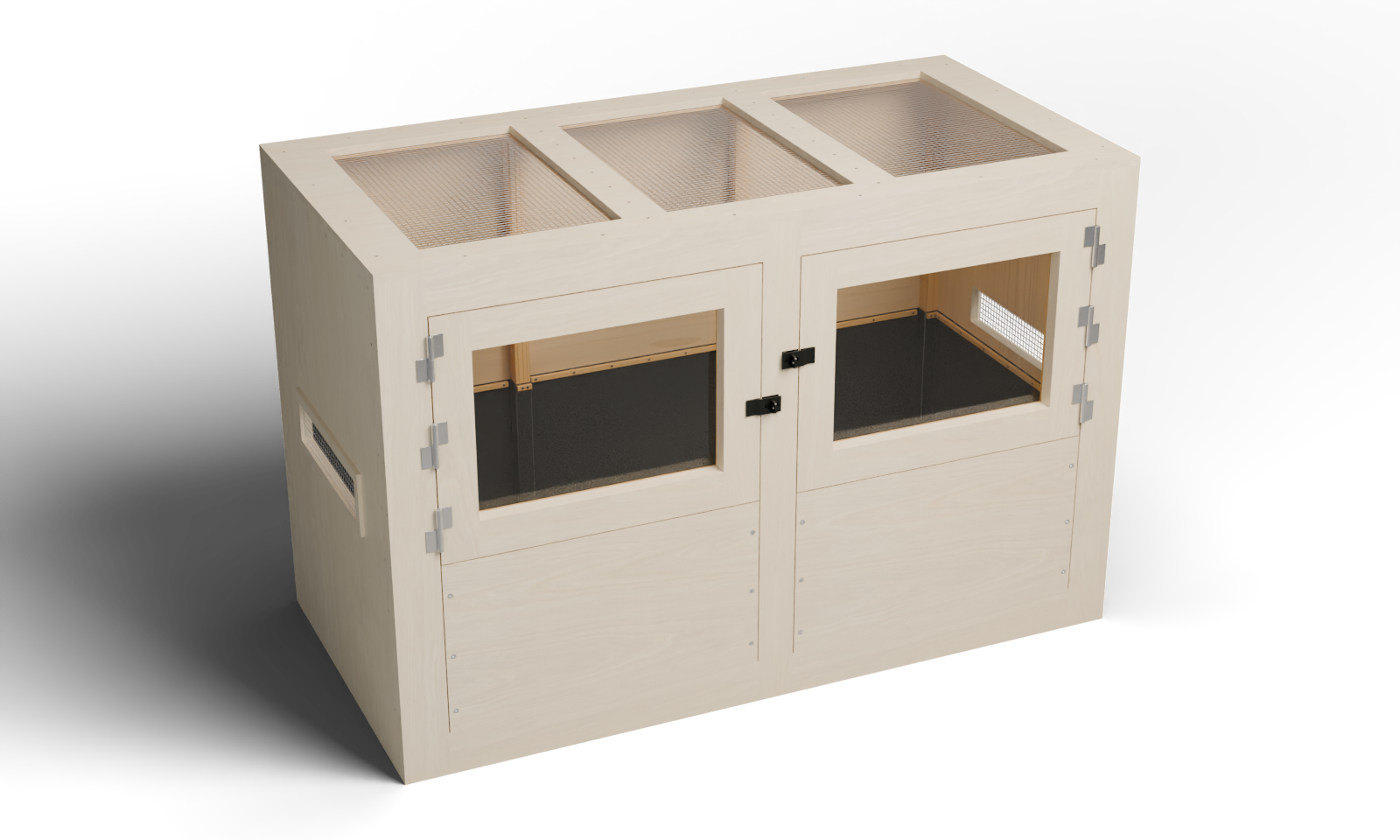
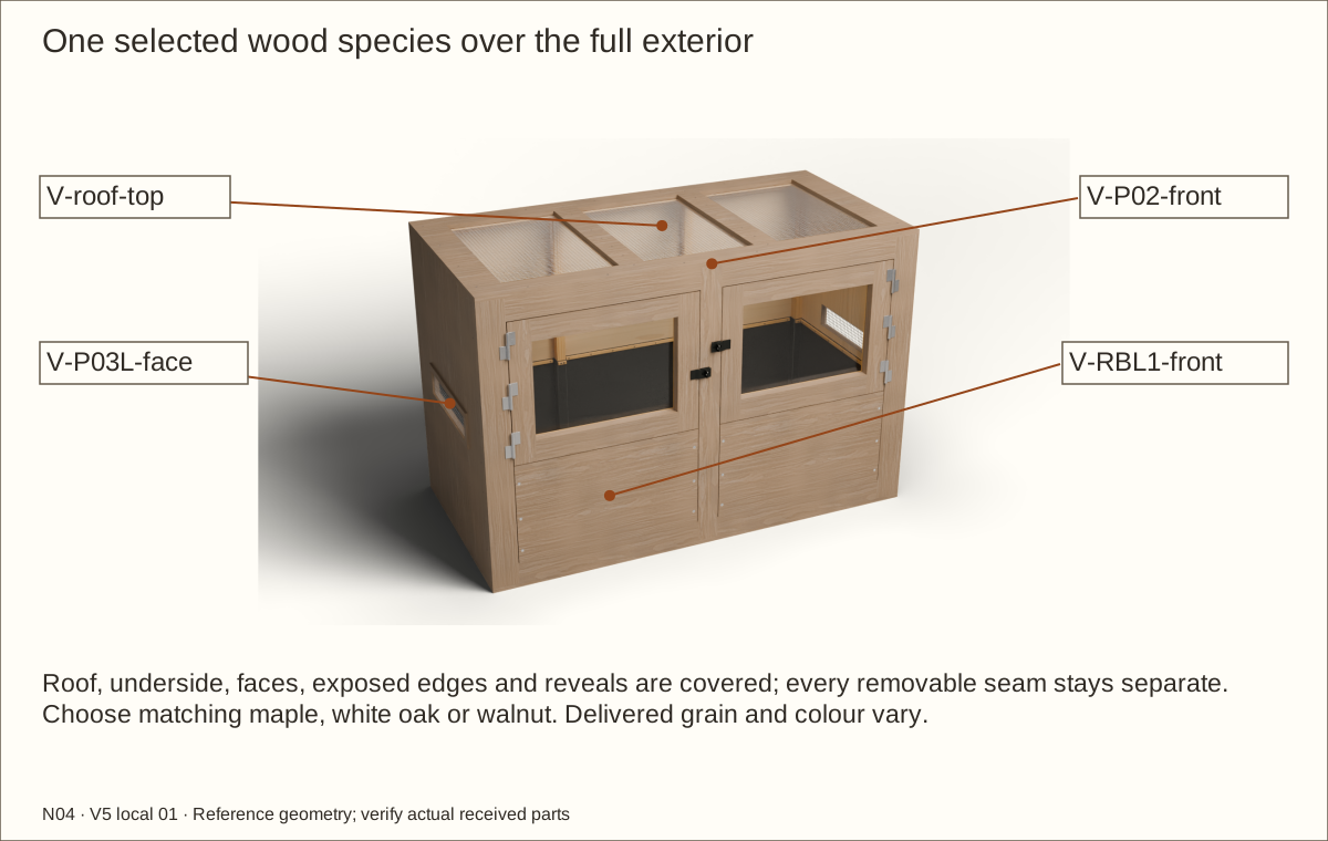
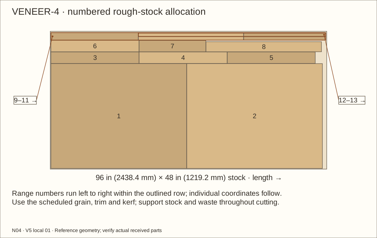
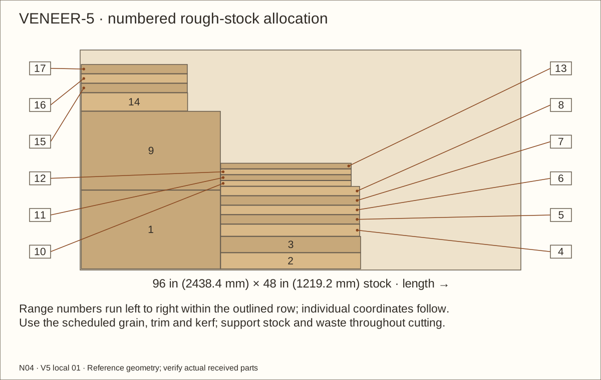
Full exterior veneer: the roof, faces, edges and reveals are included in this guide’s coordinated veneer schedule and geometry. Supplier balance, bond and actual-stack acceptance remain required. Natural grain and color vary.
About these previews
Rendered from this enclosure’s actual reference geometry. Veneer layers preserve service seams and bare hasp seats. Hinges bear on the accepted cured face veneer. The 3D viewer shows maple; these choices change the main picture. Texture scans by Jenelle van Heerden via Poly Haven, CC0 illustrate appearance and are not delivered veneer samples.
Two lift-off acrylic doors, a continuous lined bed behind two removable three-layer retainers, and three screened roof openings. Follow 67 pictured operations with named parts, required waits and checks before continuing.
Construction holds: exact hinge/hasp seating, veneer bearing/balance/bond, recessed retainer connections, floating glazing, uncut liner folds, prototype construction, physical testing, qualified review, and site-specific support and stability acceptance remain open.
This is the individual N04 hinged lined design. Receive, measure and trial exact materials before dependent final cuts. A changed plywood gauge, lining, hardware or veneer system requires coordinated recalculation.
Measurement
Reference
Bare case
72 × 36 × 48 in (1828.8 × 914.4 × 1219.2 mm)
Reference covered case
72.061 in (1830.35 mm) × 36.061 in (915.95 mm) × 48.061 in (1220.75 mm)
Maximum covered case
72.092 in (1831.14 mm) × 36.092 in (916.74 mm) × 48.092 in (1221.54 mm)
External capture width
72.811 in (1849.4 mm); allow additional hardware/service room
Finished floor / bed
Floor 53/64 in (21.03 mm) above underside; maximum total bed 18 in (457.2 mm)
Bare leaf size
29 45/64 in (754.46 mm) × 22 19/32 in (573.88 mm) × 1 1/2 in (38.1 mm)
Bare opening above retainer
30 3/64 in (763.19 mm) × 22 31/32 in (583.41 mm)
Removed-door opening
29.9859 in (761.64 mm) × 22.9078 in (581.86 mm) at reference veneer
Complete veneer layer
Reference 0.0305 in (0.77 mm); maximum 0.046 in (1.17 mm)
Datums: assembly X starts at outside LEFT, Y at outside FRONT and Z at FLOOR UNDERSIDE, unless a local part edge is explicitly named. in means inches; mm means millimetres. Exact mating decimals are retained; actual received measurements govern.
Tools, terms and safe workholding
Prepare a padded flat bench, helper, clamps, straight cauls, tape, square, marking knife, straightedge, caliper and drill depth stops. Use supported saw/router/jigsaw setups and sacrificial backing. Follow each tool maker’s guards and minimum feed lengths; never feed narrow short strips without a suitable carrier.
For retainer trials: 1-inch (25.4 mm) flat-bottom boring bit with a 5/8-inch (15.88 mm) stop, 9/32-inch (7.14 mm) through bit, 82-degree countersink, 5/32-inch (3.97 mm) hex hand driver and 7/16-inch (11.11 mm) socket no wider than 7/8 inch (22.23 mm). Prove actual bit-point depth and driver/socket clearance on matching scrap. Use root-matched wood pilots and correct hand drivers. Mesh needs snips and edge protection; veneer needs a sharp knife and supplier-specified pressure tool. Use the acrylic maker’s accepted supported cutting and edge-finishing method.
Wear eye/hearing protection, control dust and ventilate adhesives/coatings. Protect hands while handling wire and metal; keep gloves and loose clothing away from rotating tools. Support both work and waste.
Term
Plain meaning
Cleat / lamination
Wood strip receiving screws / layers joined face to face
Jamb / header / retainer
Side of the opening / top frame member / removable front bed wall
Rear edge cut narrower for swing clearance / supported upward removal from hinge pins
PSA / RH
Pressure-sensitive adhesive / relative humidity
EPDM / mil
Ethylene propylene diene monomer rubber / one thousandth of an inch
Record the actual stock and shared heights
Plywood thickness: t = ______ in / ______ mm Compressed underlay + liner: a = ______ in / ______ mm Finished-floor elevation: F = t + a = ______
Part / elevation
Equation in inches
Reference
Floor / roof
72 × 36
72 × 36 in (1828.8 × 914.4 mm)
Side height
48 − 2t
46 19/32 in (1183.48 mm)
Back width
72 − 2t
70 19/32 in (1793.08 mm)
Fixed frame / bare bay width
(72 − 2t − 3 × 3.5) / 2
30 3/64 in (763.19 mm)
Retainer width
Bare bay width − 2 × 5/32
29 47/64 in (755.25 mm)
Retainer top
F + 20
20 53/64 in (529.03 mm)
Retainer height
F + 20 − (t + 3.5)
16 5/8 in (422.28 mm)
Maximum bed top
F + 18
18 53/64 in (478.23 mm)
Clamp screw centre
F + 19 3/8
20 13/64 in (513.16 mm)
Liner top
F + 19 3/4
20 37/64 in (522.68 mm)
These equations retain the original core and nominal frame sections. They do not automatically update all joints, hole stations, hinge axes or glazing sizes. Recalculate the entire coordinated candidate whenever a measured input changes. Transfer shared heights with a marked measuring strip.
Why the hinge face stack matters
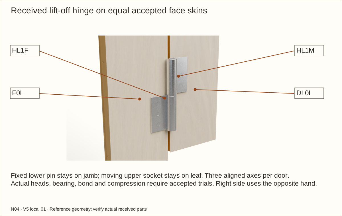
Both lift-off halves mount on equal accepted cured veneer faces
The reference barrel is tangent to its mounting plane. Recessing only the flat leaf into veneer makes that barrel rub the remaining skin. Here the complete unaltered hinge and shared axis move forward by the actual cured face stack: 0.0305 in (0.77 mm) at reference. Keep both bearing faces equally thick, flat, fully bonded and accepted for compression under the leaves. The actual screw heads, supplied holes, bond and bearing require a qualified material trial before drilling the real frame.
Parts: Complete enclosure, support and received inventory, as described below
Tools / setup: Measuring tape, square, pencil and the tools named below
Qualify the support and service position — 1
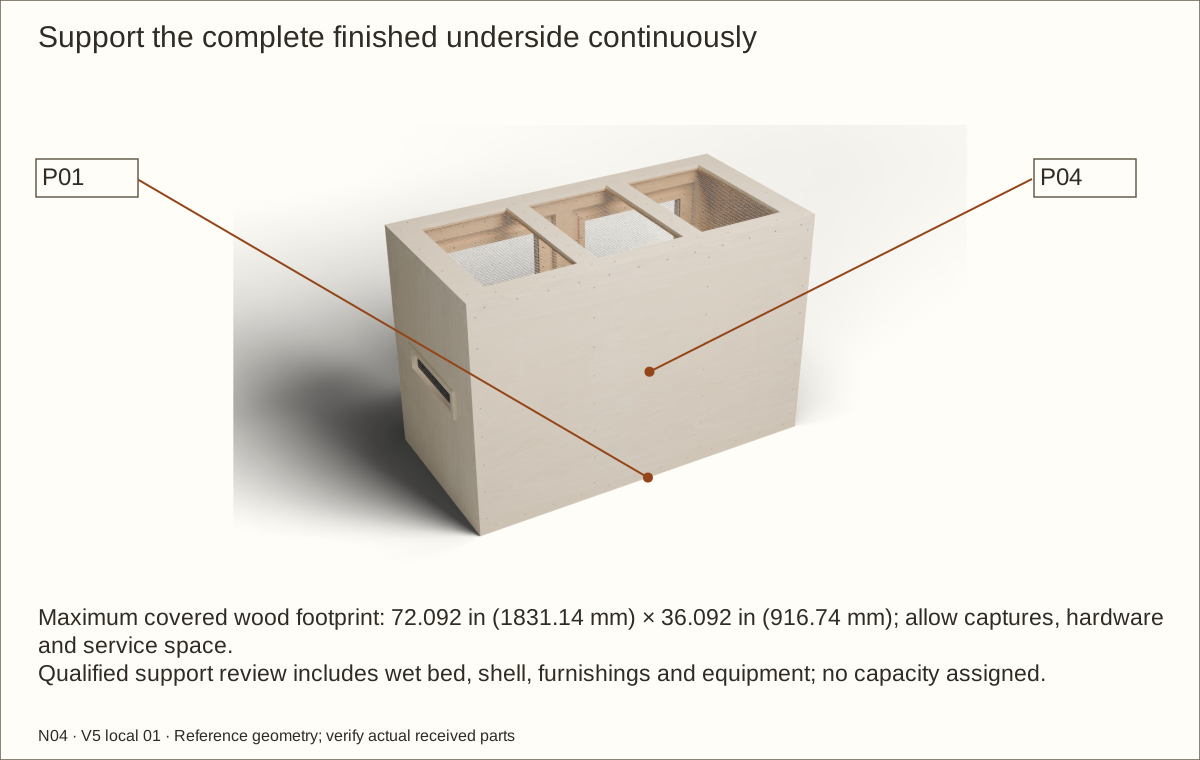
Use a qualified level rigid support under the complete finished underside, at least 72.092 in (1831.14 mm) wide × 36.092 in (916.74 mm) deep at the maximum skin. Every edge bears continuously; the guide does not design a stand or qualify the building floor.
The conservative bed envelope is 24.13 cubic feet (683 L), before framing displacement. At an assumed wet bulk density of 100 lb/ft³ (1602 kg/m³), the bed alone would weigh 2413 lb (1095 kg). Add the shell, water, rocks, furnishings and equipment when qualifying both furniture and building floor.
Check before continuing: Qualified full-footprint support and the complete load assumptions are recorded before construction.
Parts: Complete enclosure, support and received inventory, as described below
Tools / setup: Measuring tape, square, pencil and the tools named below
Qualify the support and service position — 2
Keep at least 32 in (812.8 mm) working space in front, 6 in (152.4 mm) beside each door swing, complete roof access and at least 2 in (50.8 mm) above each opened leaf for lift-off. The side captures make reference width 72.811 in (1849.4 mm). Allow separately for the real hinges, hasps, tools and handling.
Place and stabilize the empty enclosure at its final location. Provide furniture restraint appropriate to that support and wall where tipping is possible. Never stack, suspend, climb on, lift or tip the loaded shell.
Check before continuing: The entire floor is supported and the load and cleaning routes have been checked before construction.
Parts: Complete enclosure, support and received inventory, as described below
Tools / setup: Measuring tape, square, pencil and the tools named below
Receive and measure all materials — 1
Measure the actual plywood thickness at several points. Check pine is 3/4 in (19.05 mm) thick and solid wood supports are 1 1/2 in (38.1 mm) square. Reject warped, split or damaged wood and knots at joints.
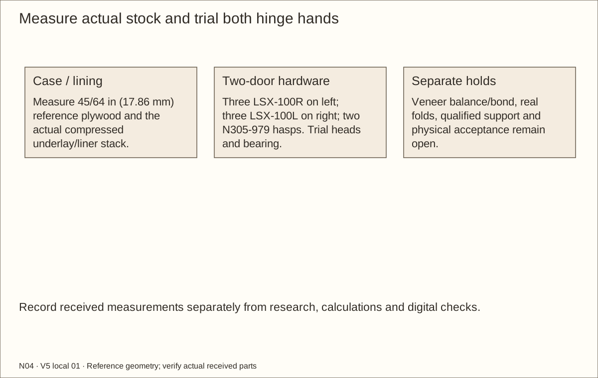
Receive all six LSX-100 lift-off hinges, both N305-979 hasps and their exact screws. Compare their hands with the hinge drawing: fixed pins point upward, moving sockets are above. Confirm all three hinges on each jamb have the same hand. Three LSX-100R serve the left door; three LSX-100L serve the right. Confirm actual head seating and full bearing before drilling. H01 remains open until received hardware and the trial are accepted.
Check before continuing: Actual wood gauge, all six matching handed hinges and received materials are recorded.
Parts: Complete enclosure, support and received inventory, as described below
Tools / setup: Measuring tape, square, pencil and the tools named below
Receive and measure all materials — 2
Measure the actual 0.22 in (5.59 mm) acrylic, two separate uncompressed 1/16 in (1.59 mm) neoprene face pads, cured contact films and compressed underlay/liner sample. The bare spacer reference 0.351 in (8.92 mm) leaves a 0.345 in (8.76 mm) finished cavity after two 0.003 in (0.08 mm) films. The 0.08 in (2.03 mm) compressed underlay plus 0.045 in (1.14 mm) EPDM reference totals 1/8 in (3.18 mm); these are not delivered measurements.
On a spare strip, mark the floor underside. Above it, mark the actual plywood thickness plus compressed lining to locate the finished floor. From that mark, measure up 18 in (457.2 mm) for the maximum bed, 20 in (508 mm) for the retaining-panel top and 21 in (533.4 mm) for the vent bottom. Transfer these marks to the build.
Check before continuing: All materials and handed hardware are identified; actual plywood and compressed lining thicknesses are recorded.
Tools / setup: Measuring tape, square, pencil and the tools named below
Before you begin: Support both sides of every cut and use eye/hearing/dust protection. Never reach across a running blade.
Cut and identify the plywood — 1
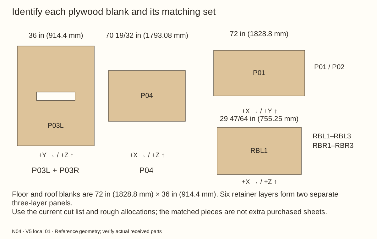
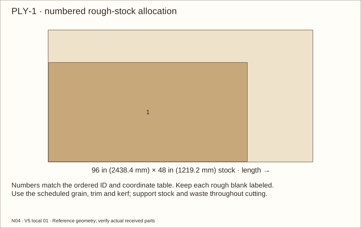
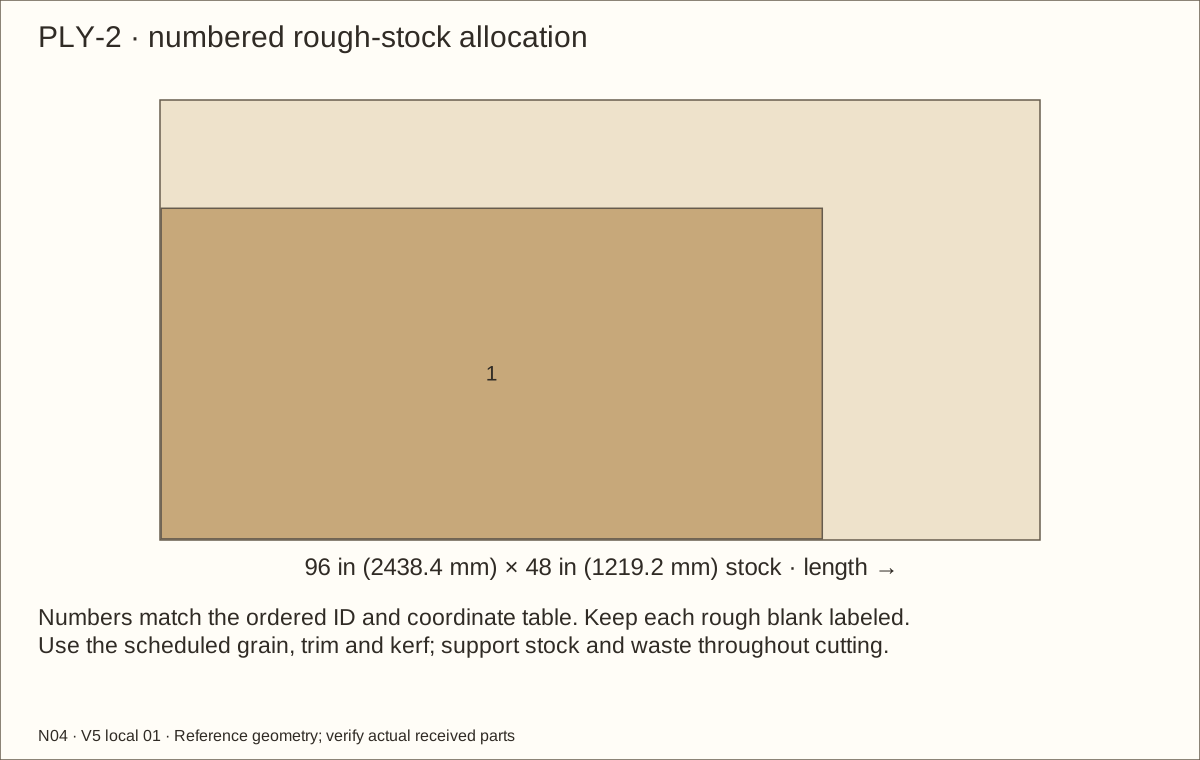
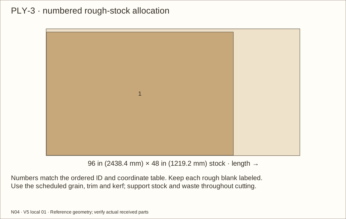
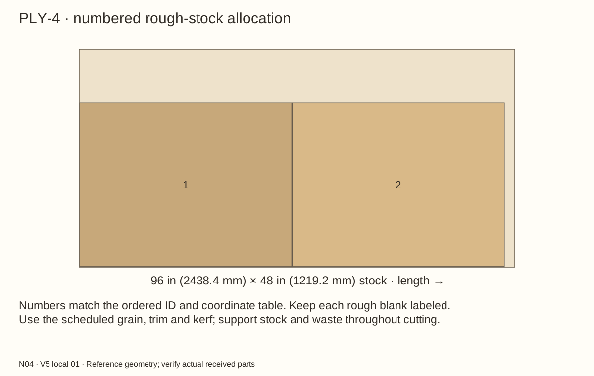
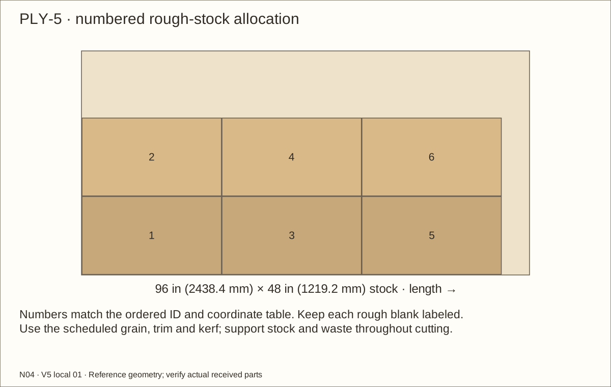
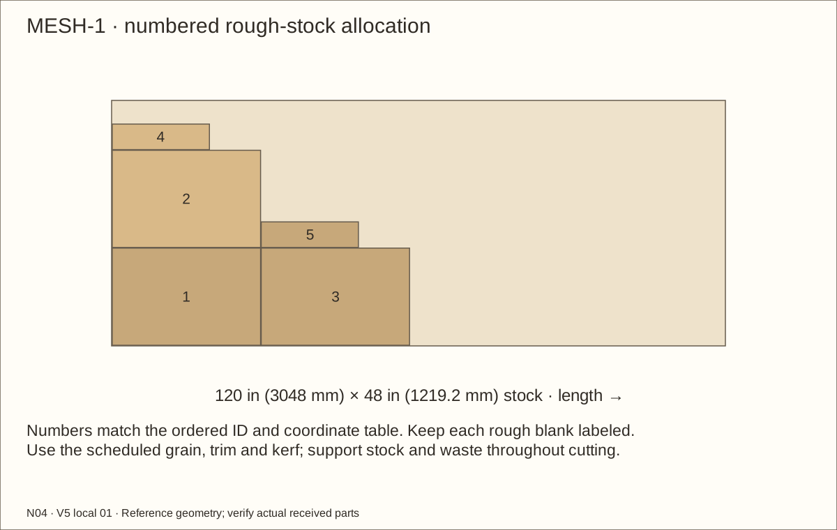
Follow this build’s 5 current plywood-sheet layouts. Square and label each sheet; floor P01 and roof P02 finish at 72 in (1828.8 mm) × 36 in (914.4 mm). Keep 1/8 in (3.18 mm) saw-cut waste between rough blanks and support both sides of every cut.
At the 45/64 in (17.86 mm) plywood reference, each side finishes at 36 in (914.4 mm) × 46 19/32 in (1183.48 mm) and the back at 70 19/32 in (1793.08 mm) × 46 19/32 in (1183.48 mm). Fit sides between floor and roof and back between sides to preserve the 48 in (1219.2 mm) bare height. Use the actual cut layouts, rough allowances and grain directions.
Check before continuing: Floor, roof, paired walls and back are labeled, square and fitted to the actual plywood gauge.
Tools / setup: Measuring tape, square, pencil and the tools named below
Before you begin: Support both sides of every cut and use eye/hearing/dust protection. Never reach across a running blade.
Cut and identify the plywood — 2
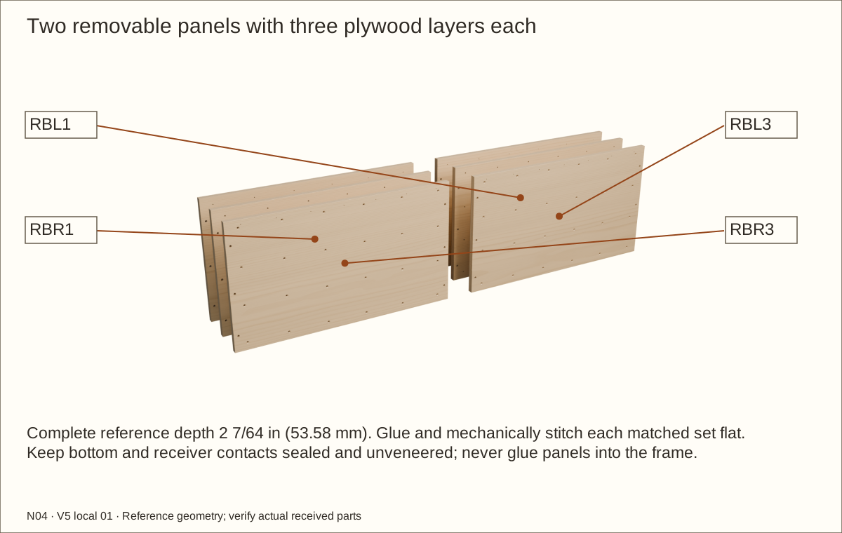
Cut two matched sets of three retainer layers, RBL1–RBL3 and RBR1–RBR3. Each finished layer is 29 47/64 in (755.25 mm) wide × 16 5/8 in (422.28 mm) high. Keep widthwise grain, 5/32 in (3.97 mm) bare side gaps, and unveneered sealed bottom/receiver bearing faces.
Label every part, its inside face and its measuring edge before cutting. Use inch markings throughout each cut; metric values are rounded equivalents. Sizes marked “about” are starting marks. Leave the line, then fit each piece to its actual adjoining parts before the final cut.
Check before continuing: Paired side panels and all six retainer layers are square, labeled and matched.
Tools / setup: Measuring tape, square, pencil and the tools named below
Cut the roof openings and side vents — 1
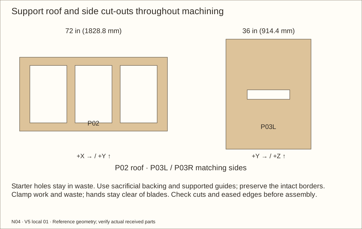
Mark three 18 in (457.2 mm) × 28 in (711.2 mm) roof openings, with left edges 5 in (127 mm), 27 in (685.8 mm) and 49 in (1244.6 mm) from the left and front edges 4 in (101.6 mm) from the front. Keep both 4 in (101.6 mm) webs intact.
On each side, mark an 18 in (457.2 mm) × 4 in (101.6 mm) vent starting 9 in (228.6 mm) behind the front. Its bottom is 21 in (533.4 mm) above the finished-floor mark, not above the panel’s lower edge.
Check before continuing: All three roof and both side-vent outlines match this build and its finished-floor datum before cutting.
Tools / setup: Measuring tape, square, pencil and the tools named below
Cut the roof openings and side vents — 2
Drill starter holes inside the waste and use a guided router or supported jigsaw. Stay inside the corner lines, ease the reveals and remove all splinters.
Dry-place the capture strips and check their screws land in solid wood outside each opening. The inner reveal stays smooth; the outer strips capture the cut wire edges.
Check before continuing: Vents begin 3 in (76.2 mm) above the maximum fill; all roof borders and both rib webs remain.
Tools / setup: Measuring tape, square, pencil and the tools named below
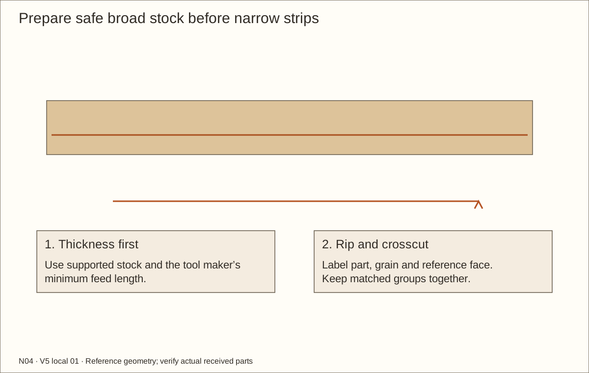
Before you begin: Plane broad supported stock first; never feed short thin strips alone.
Prepare the frame stock and thin strips — 1
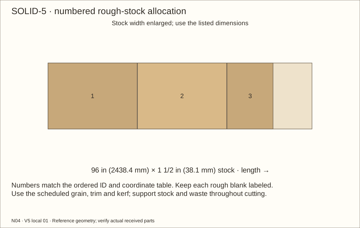
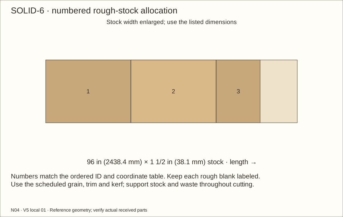
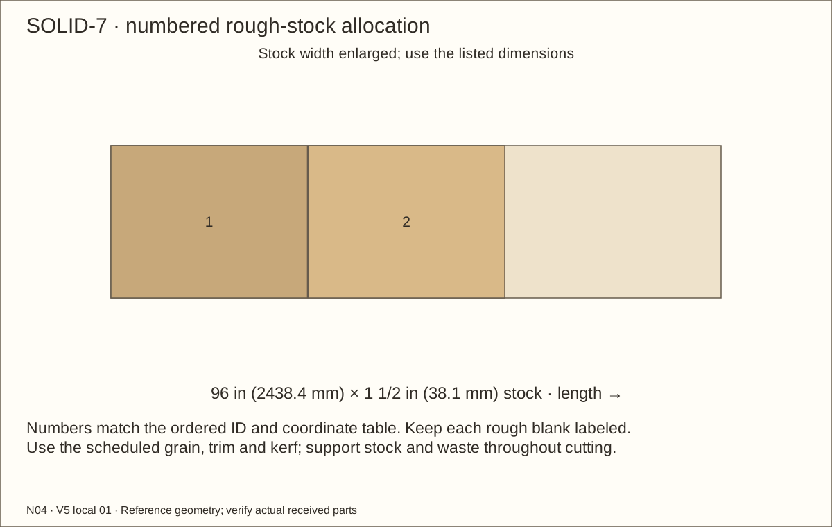
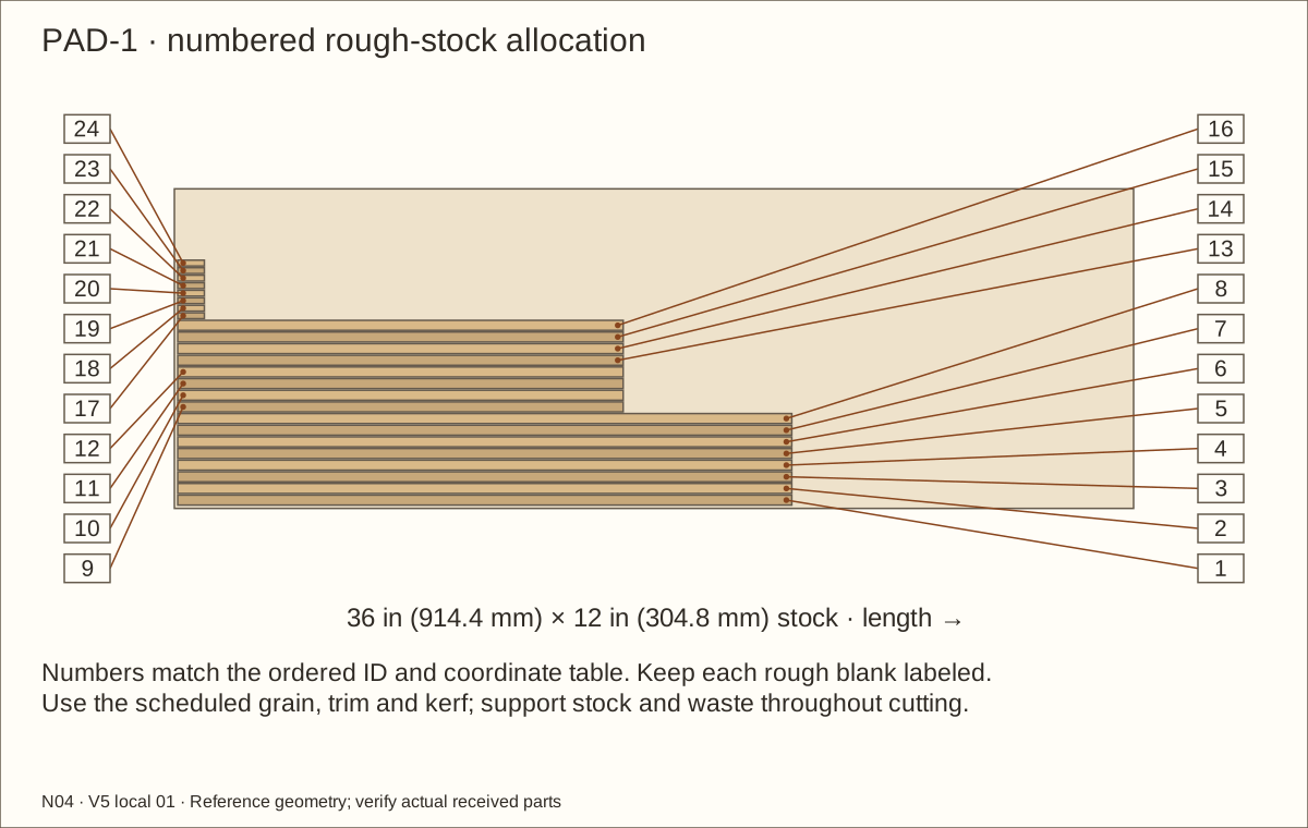
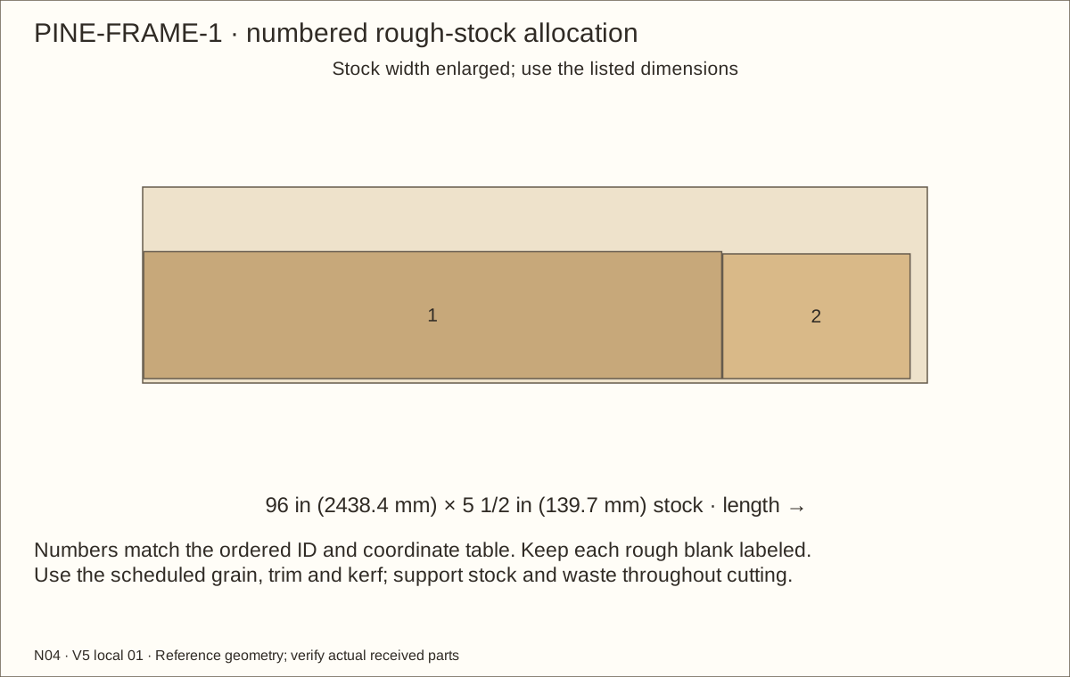
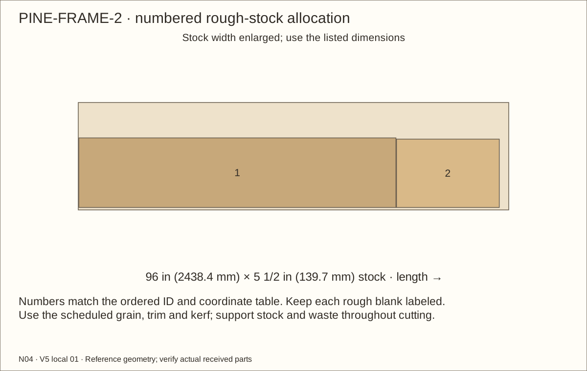
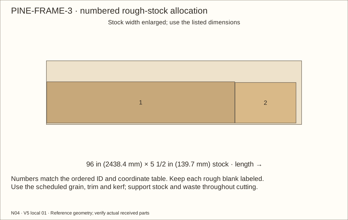
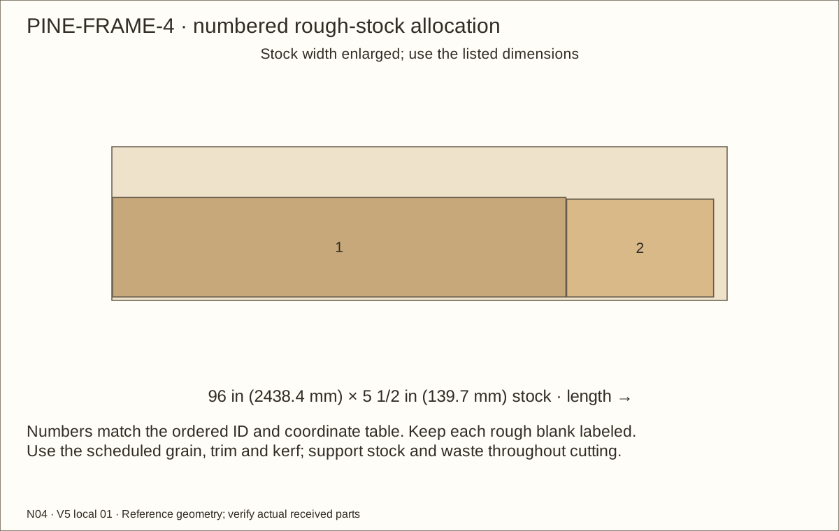
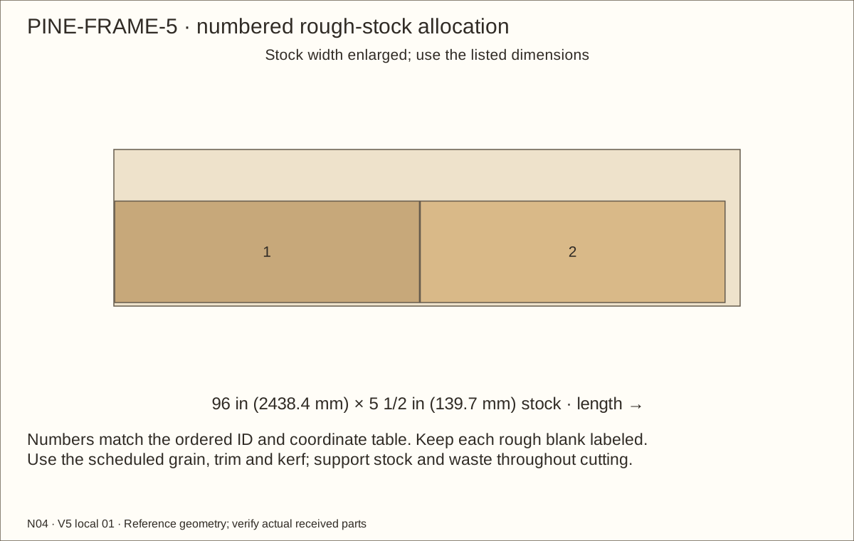
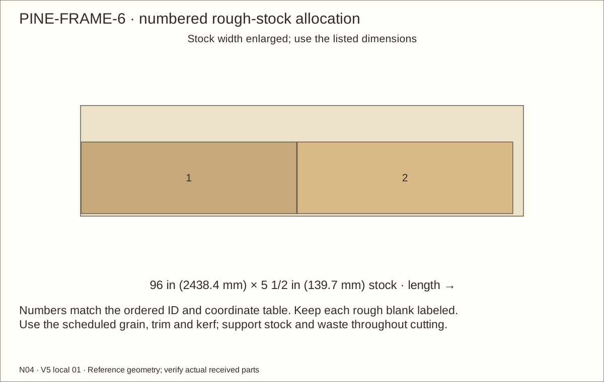
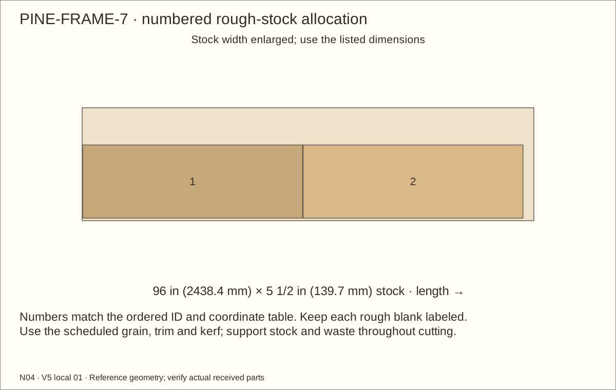
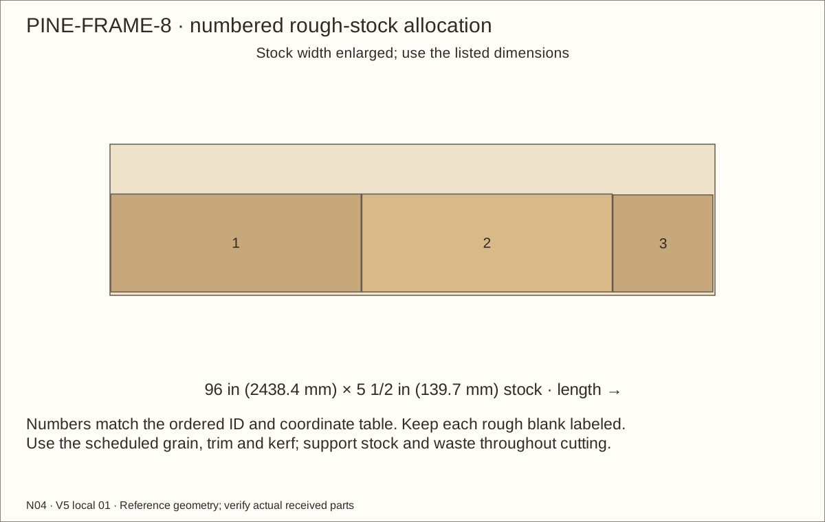
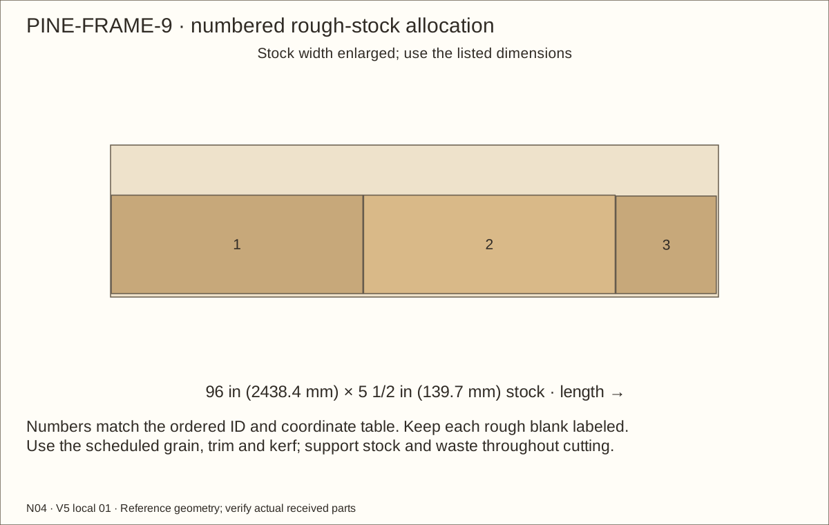
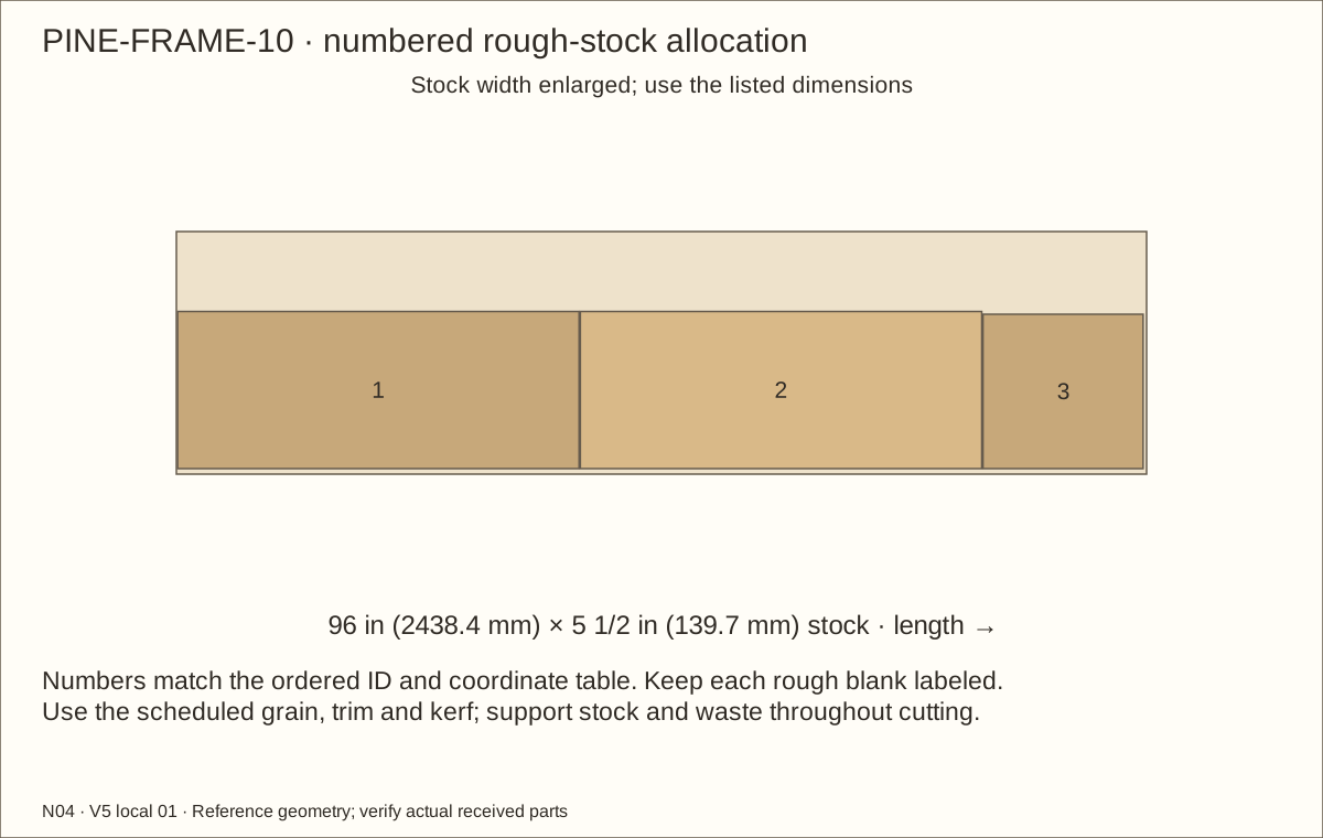
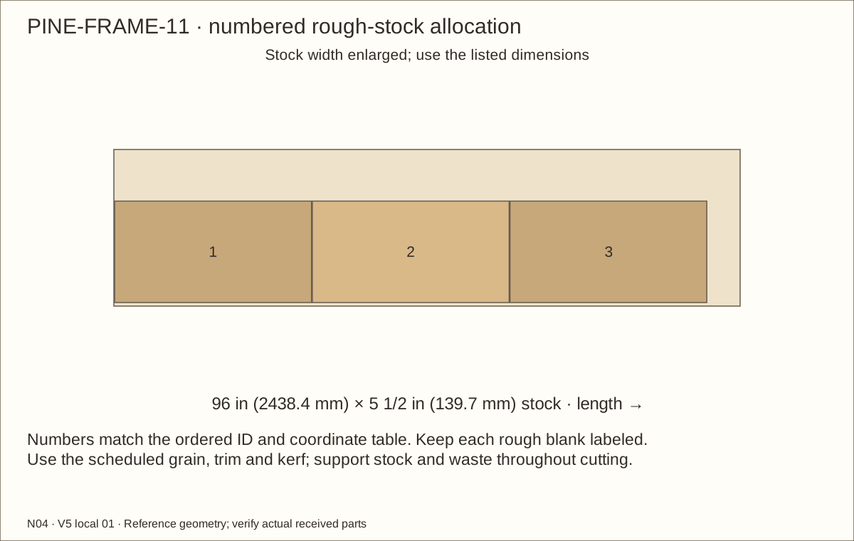
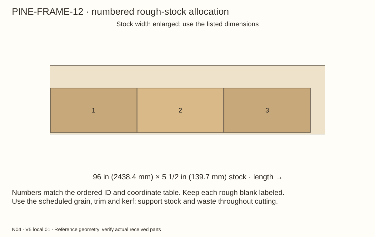
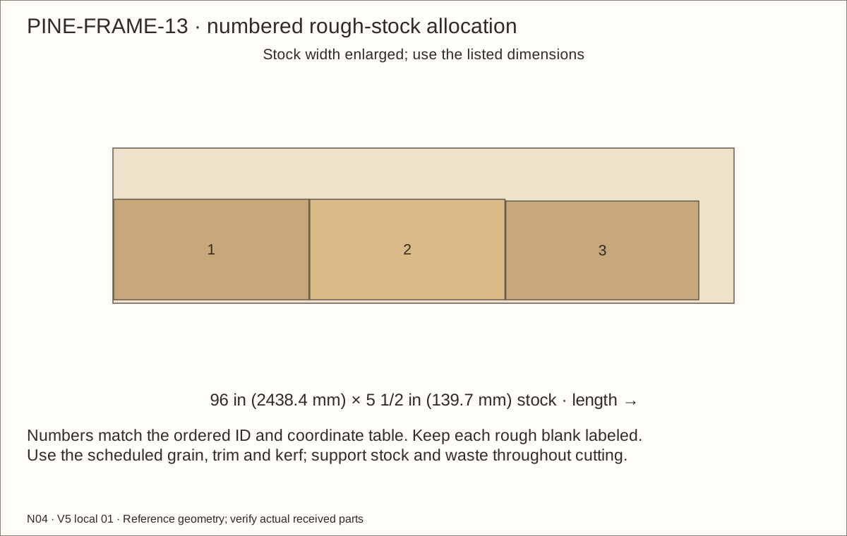
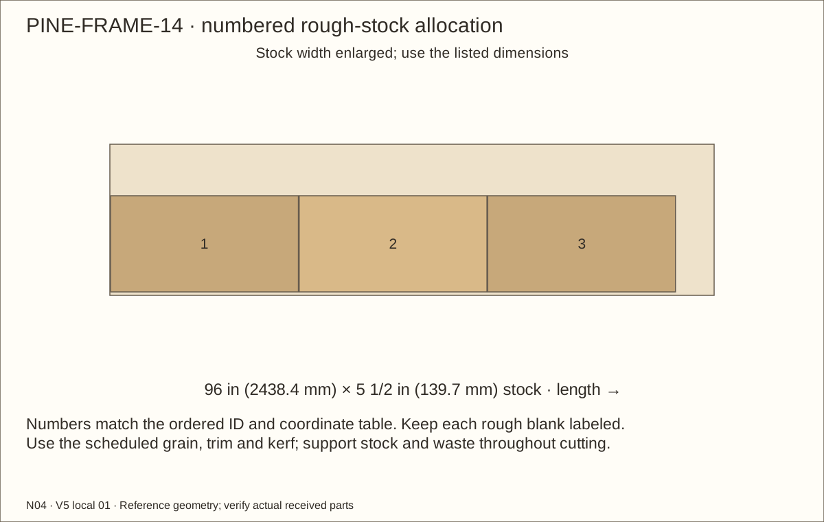
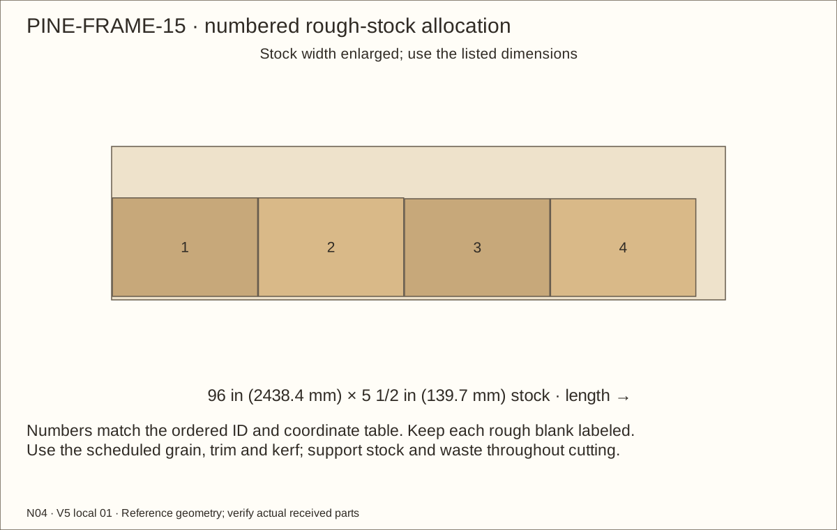
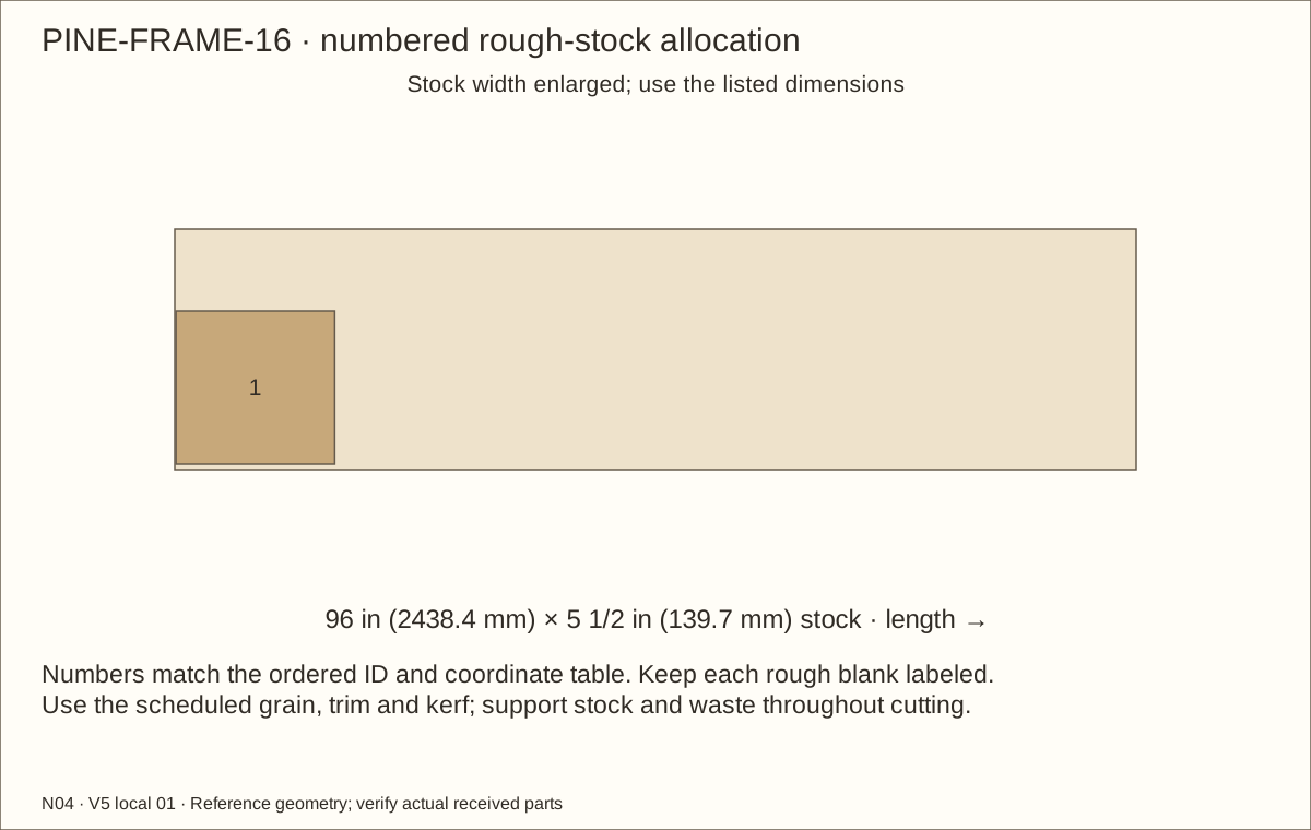
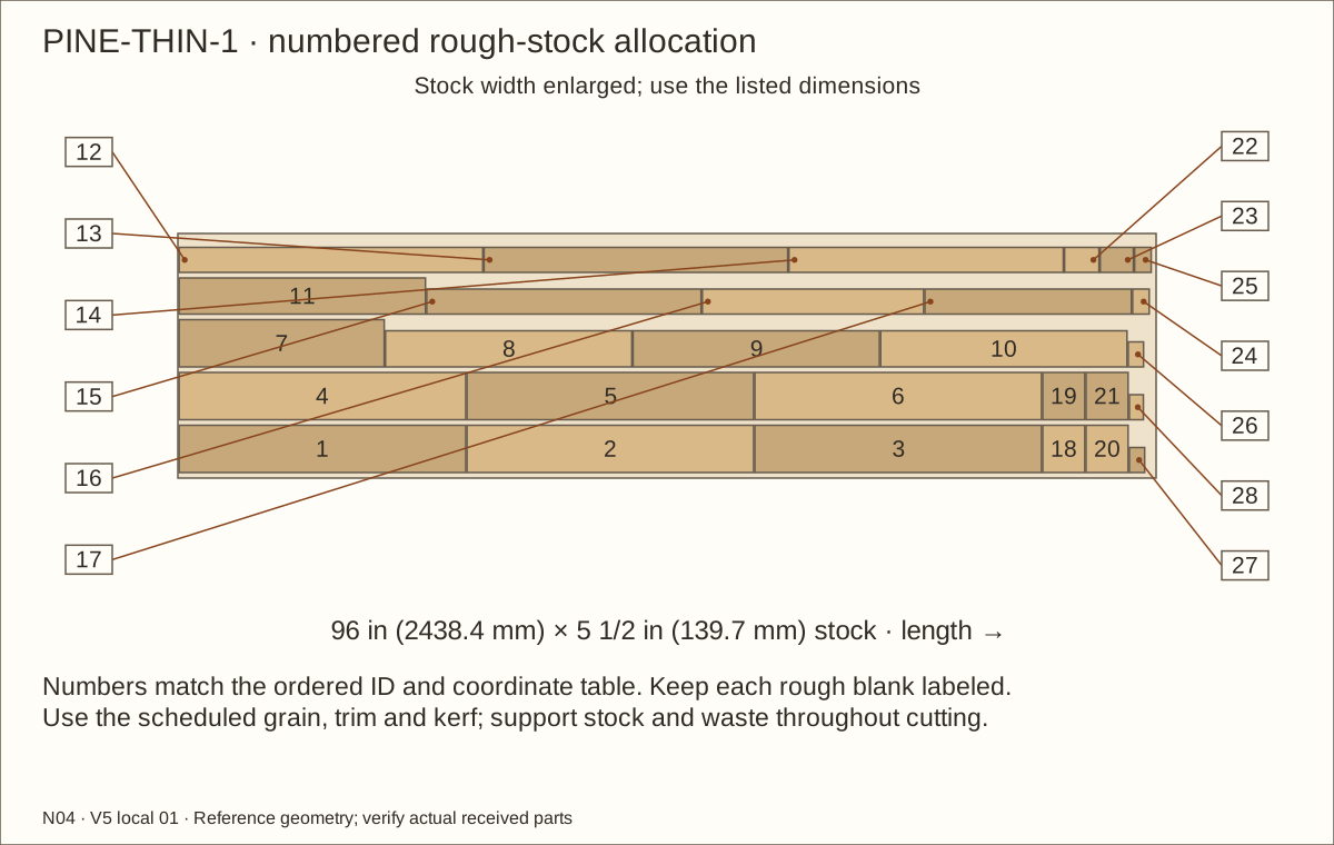
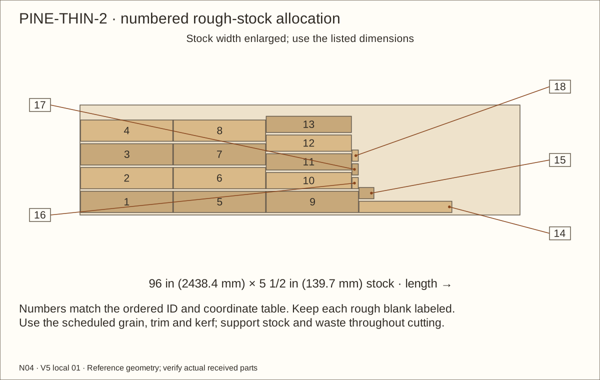
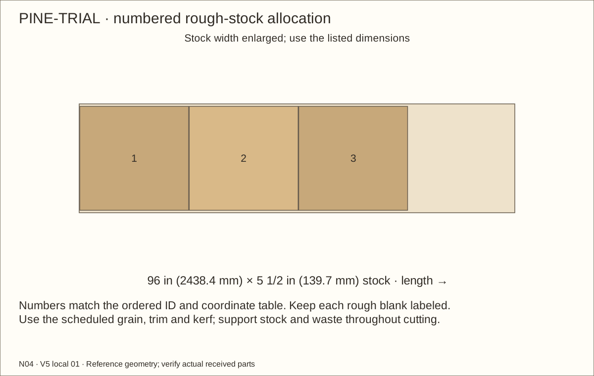
Follow current PINE-FRAME allocations for all 24 fixed-frame pieces and sixteen door pieces from straight 3/4 in (19.05 mm) × 5 1/2 in (139.7 mm) × 96 in (2438.4 mm) stock. Rip scheduled 3 1/2 in (88.9 mm) broad strips with guards, push sticks and supported stops, then crosscut each labeled piece; preserve 1/8 in (3.18 mm) saw waste.
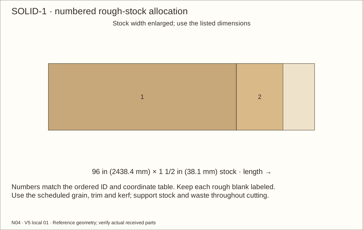
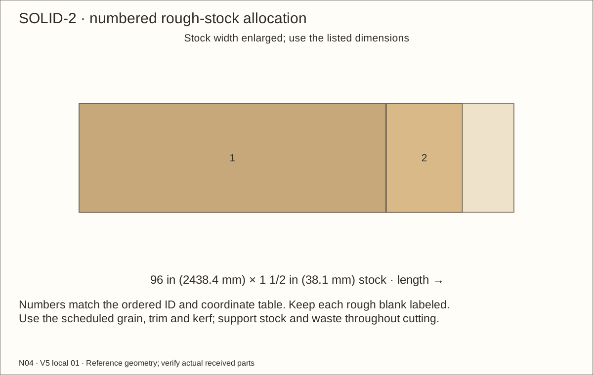
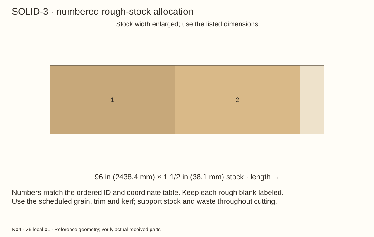
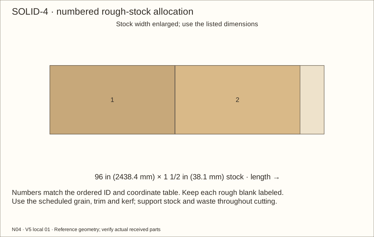
Use current SOLID layouts for every named 1 1/2 in (38.1 mm) square support, four full-height rear uprights, two roof ribs and four short panel receivers. Keep full solid section and square bearing faces; no laminated substitutes are assumed.
Check before continuing: Named supports and frame blanks match their stock allocations and grain direction.
Tools / setup: Measuring tape, square, pencil and the tools named below
Before you begin: Plane broad supported stock first; never feed short thin strips alone.
Prepare the frame stock and thin strips — 2
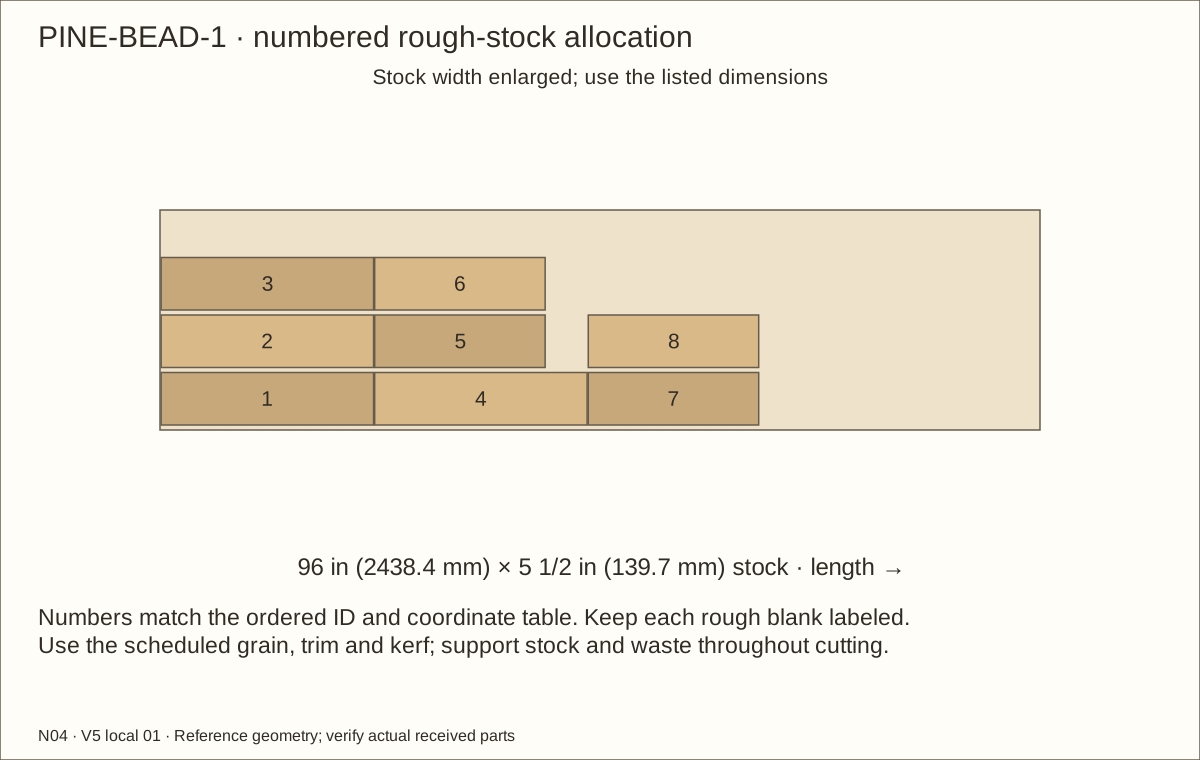
Plane broad supported stock to 3/8 in (9.53 mm) before ripping the 1 in (25.4 mm) mesh captures and 1/2 in (12.7 mm) lining clamps. Route the separate wire rebates with solid outer screw lands. Never feed short finished strips alone into a planer.
Prepare glazing spacers from 3/8 in (9.53 mm) rough thickness and rear beads from 1/4 in (6.35 mm) stock. Retain specified widths; plane the spacer to the received pane, two uncompressed pads and cured films, 0.351 in (8.92 mm) bare reference. Use qualified milling if guarded equipment cannot support the work.
Check before continuing: Each current stock allocation preserves grain, rough allowances and saw-cut waste.
Tools / setup: Measuring tape, square, pencil and the tools named below
Before you begin: Glue is supplementary; every mechanical stitch is required. Keep fresh layers flat and unstressed.
Laminate the continuous front frame — 1
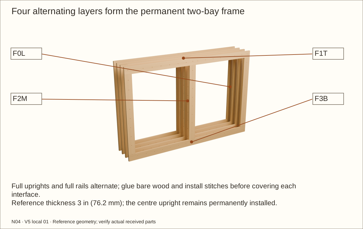
Dry-lay layer 1 with all three uprights running full height; fit its split top and bottom rails between them. In layer 2, both rails run full width and the uprights fit between them. Repeat these arrangements for layers 3 and 4.
Dry-fit the four-layer frame to 70 19/32 in (1793.08 mm) wide × 46 19/32 in (1183.48 mm) high and 3 in (76.2 mm) deep. The centre upright is 3 1/2 in (88.9 mm) wide, centred at X = 36 in (914.4 mm). Each bay is 30 3/64 in (763.19 mm) wide at reference; compare both diagonals and use matched gauges at the top and bottom.
Check before continuing: All four fixed-frame layers dry-fit square with the center upright and permanent kick rail correctly aligned.
Tools / setup: Measuring tape, square, pencil and the tools named below
Before you begin: Glue is supplementary; every mechanical stitch is required. Keep fresh layers flat and unstressed.
Laminate the continuous front frame — 2
Fit one layer at a time. Transfer its scheduled rear-entry stitch holes, clearance-drill the new layer and pilot into the preceding one. Spread Titebond III on the mating bare faces, clamp flat with straight clamping pads and fit every #8 × 1 1/4 in (31.75 mm) stitch screw before the next layer covers it. Adjacent layers use offset stations; every seam is bridged. Glue is supplementary, not a claimed structural adhesive. Glue only the layer being fitted: the published open time is 8–10 minutes at 70°F (21°C) and 50% relative humidity. Prepare all clamps and holes first; complete one interface before starting another.
Wipe squeeze-out and keep the frame flat and unstressed for at least 24 hours, longer if the received glue label or conditions require. Do not glue the removable retainers, roof or shell panels to this assembly.
Check before continuing: The full frame is 3 in (76.2 mm) deep, square and flat, with a fixed centre vertical divider and bottom kick rail.
Required wait: Glue: at least 24 hours unstressed; follow the received label
Tools / setup: Measuring tape, square, pencil and the tools named below
Laminate both unglazed door frames — 1
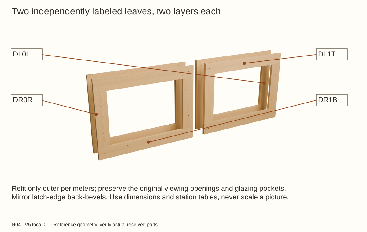
Prepare matching oversized layers for each door dry fit. After lamination and full cure, refit only the outer perimeter to 29 45/64 in (754.46 mm) wide × 22 19/32 in (573.88 mm) high. Preserve its original sight opening and rear glazing datums. Bare gaps: 3/16 in (4.76 mm) at hinge, top and bottom; 5/32 in (3.97 mm) at latch. The two mirrored leaves remain separately labeled.
In the front layer, uprights run full height and rails fit between them. In the rear layer, rails run full width and short uprights fit between them. Dry-fit and compare diagonals before applying glue.
Check before continuing: Both door-layer sets dry-fit flat and square with staggered joints and unchanged glazing datums.
Tools / setup: Measuring tape, square, pencil and the tools named below
Laminate both unglazed door frames — 2
Clearance-drill the rear layer at its eight scheduled stitch positions and pilot into the front layer. Apply Titebond III, clamp flat and fit all eight #8 × 1 1/4 in (31.75 mm) rear-entry screws per leaf. Keep the sight opening and outer edges square. Do not attach glazing yet.
Leave each leaf flat and unstressed for at least 24 hours. Mark left and right without relying on the purchased hinge’s hand name.
Check before continuing: Each door is a flat, square, 1 1/2 in (38.1 mm) thick laminated frame, ready for the unglazed fitting trial.
15. Laminate the two removable retaining panels — 1
Parts: RBL1, RBL2, RBL3, RBR1, RBR2, RBR3
Tools / setup: Measuring tape, square, pencil and the tools named below
Before you begin: Keep retainer laminations distinct from the fixed frame. Do not glue the service joint.
Laminate the two removable retaining panels — 1
Match RBL1–RBL3 for the left panel and RBR1–RBR3 for the right. Dry-stack each set face to face, flush at every edge, and check it against the corresponding bay. Refit each panel with 5/32 in (3.97 mm) bare side gaps. Its underside bears directly on the sealed fixed kick rail; no veneer beneath it or against receiver contact faces.
Transfer the rear-entry stitch grid while each stack is clamped. Drill #8 clearance through its rear and middle layers, then stopped pilots into the front layer. Apply Titebond III, clamp with straight clamping pads and install the scheduled #8 × 2 in (50.8 mm) screws from the rear. Their tips retain about 7/64 in (2.78 mm) front cover in the reference stack; recalculate for received thickness.
Check before continuing: Both three-layer retainer sets fit, and stitch pilots retain the required front cover.
16. Laminate the two removable retaining panels — 2
Parts: RBL1, RBL2, RBL3, RBR1, RBR2, RBR3
Tools / setup: Measuring tape, square, pencil and the tools named below
Before you begin: Keep retainer laminations distinct from the fixed frame. Do not glue the service joint.
Laminate the two removable retaining panels — 2
Keep the two panels separate from each other and the fixed frame. No glue joins them to the receiver wood supports or bottom rail; their three internal layers are the only glued interfaces.
Clean squeeze-out, label each inside face and allow at least 24 hours unstressed cure before drilling. Reject an incomplete bond rather than hiding it under finish or the liner.
Check before continuing: Each three-layer panel remains flat and removable; its total thickness matches three layers of the actual plywood.
Tools / setup: Measuring tape, square, pencil and the tools named below
Before you begin: Unresolved hardware/material holds stop the dependent operation.
Trial the hardware and glazing — 1
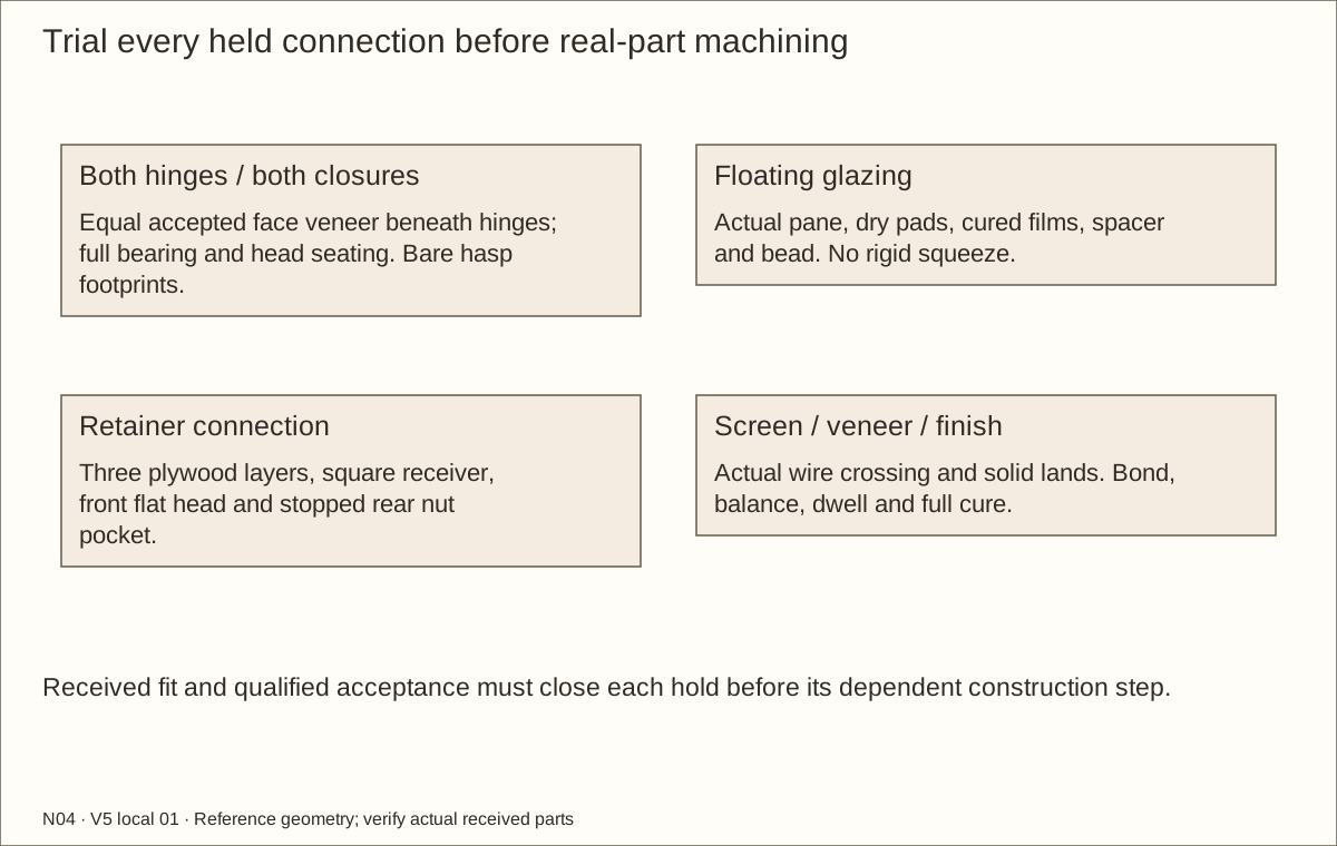
Trial both hinge hands with matching wood and the scheduled gaps. Put equal, fully cured accepted veneer coupons beneath the two leaves of each hinge, moving the complete axis forward by the measured stack (0.0305 in (0.77 mm) reference). Prove full flat bearing, bond/compression stability, head seating and buried #6 × 1 1/4 in (31.75 mm) tips. Do not machine proprietary holes without maker approval.
Check the fixed pin half remains below the removable socket and points upward. Prove an outward 100° swing and a 2 in (50.8 mm) lift after opening at least 90°. Measure actual pin engagement and removal travel; the drawing’s about 1 3/4 in (44.45 mm) projection is a reference.
Check before continuing: Both handed hinge trials prove bearing, head seating, supported swing and lift-off access.
Tools / setup: Measuring tape, square, pencil and the tools named below
Before you begin: Unresolved hardware/material holds stop the dependent operation.
Trial the hardware and glazing — 2
Trial the glazing with actual acrylic, two separate dry 1/16 in (1.59 mm) face pads and cured wood films. Fit spacer from 3/8 in (9.53 mm) rough stock to 0.351 in (8.92 mm) bare reference or the measured stack. The bead must bear on spacer wood with light pad contact, leaving the pane free to move.
Trial a complete flush connection through three actual plywood offcuts and a 1 1/2 in (38.1 mm) square receiver. Use Bolt Depot 24910 316 stainless 1/4-20 × 3 1/2 in (88.9 mm) socket flat head, 16019 washer and 16008 nylon locknut. Length includes the head. Verify 82° seat, 5/32 in (3.97 mm) hex drive, washer at most 1/16 in (1.59 mm) and actual nut height before drilling real parts.
Check before continuing: All three mockups fit the supplied hardware; no irreversible full-size hole depends on an assumed product profile.
Tools / setup: Measuring tape, square, pencil and the tools named below
Attach the bottom wood supports — 1
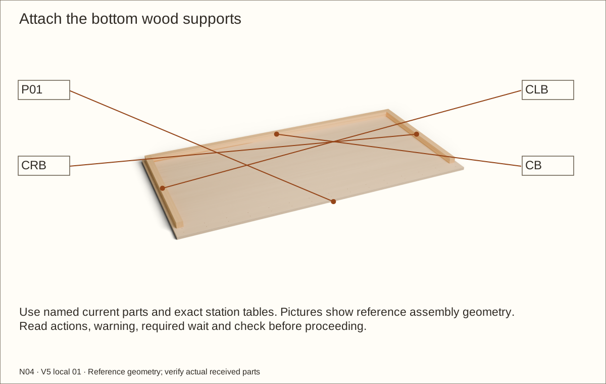
Place P01 flat on a sacrificial board. Locate CLB and CRB one plywood thickness from the side edges, starting 3 in (76.2 mm) behind the front for the laminated frame. Fit CB between them at the rear-panel position.
Transfer the hole stations listed for the bottom wood supports. Drill 11/64 in (4.37 mm) clearance through P01 only and stopped 7/64 in (2.78 mm) pilot holes into the solid pine, adjusting the pilot after an offcut trial.
Check before continuing: Floor-support positions and scheduled clearance/pilot stations match the named parts.
Tools / setup: Measuring tape, square, pencil and the tools named below
Attach the bottom wood supports — 2
Apply Titebond III to these three floor-wood support interfaces, clamp and drive #8 × 1 1/4 in (31.75 mm) screws from below. Seat heads flush with the underside so no head interrupts continuous support.
Check the front-frame and back-panel recesses, wipe squeeze-out and leave the assembly flat and unstressed through the glue cure.
Check before continuing: The floor sits entirely flat, with square wood supports and an unobstructed 3 in (76.2 mm) front-frame recess.
Required wait: At least 24 hours unstressed for glued wood supports
Tools / setup: Measuring tape, square, pencil and the tools named below
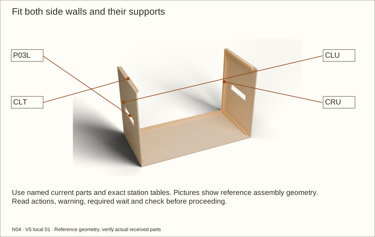
Fit both side walls and their supports — 1
Clamp each rear upright between its lower and upper wood supports. Upper wood supports start 3 in (76.2 mm) behind the front and stop at the inner face of the back panel.
With a helper, stand each wall on the floor, flush at the outer side and front edges. Clamp the wall to its bottom wood support; do not leave it standing unsupported.
Check before continuing: Both tall walls are square, supported and temporarily braced before further fastening.
Tools / setup: Measuring tape, square, pencil and the tools named below
Fit both side walls and their supports — 2
At the listed stations, clearance-drill through the plywood and pilot into the named pine receiver. Offset the future back screws from the side screws using the schedule; do not intersect their shafts.
Install #8 × 1 1/4 in (31.75 mm) screws and finish tightening by hand. Keep the wall joints dry during the trial so they can be disassembled for finish.
Check before continuing: Both walls are parallel and stable; all tips retain at least 1/16 in (1.59 mm) wood cover.
Tools / setup: Measuring tape, square, pencil and the tools named below
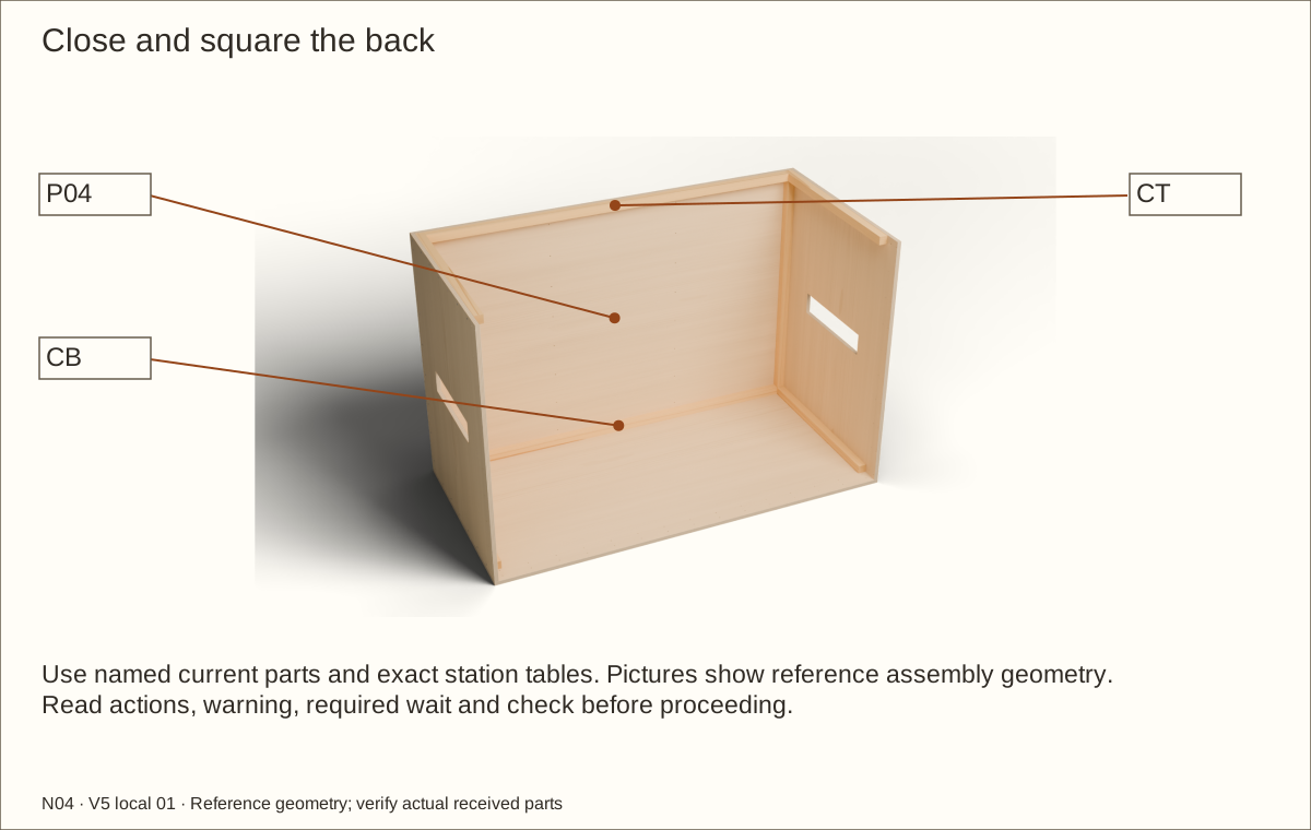
Close and square the back — 1
Fit P04 between the sides, resting on the floor and flush with their rear edges. Clamp it against CB, CT and both rear uprights.
Compare front and rear diagonals; make each pair equal within 1/16 in (1.59 mm). Correct an uneven support rather than forcing a twisted shell into position with screws.
Check before continuing: Front and rear diagonal pairs agree before final tightening of the back.
Tools / setup: Measuring tape, square, pencil and the tools named below
Close and square the back — 2
Transfer the listed stations through the back and into the receivers. Clearance-drill the plywood and use stopped pine pilots; the offset side/back stations keep screw shafts apart.
Fit #8 × 1 1/4 in (31.75 mm) screws, then remove clamp pressure and recheck the diagonals and continuous floor bearing.
Check before continuing: The square shell stands without relying on clamps; no back screw meets a side screw.
Tools / setup: Measuring tape, square, pencil and the tools named below
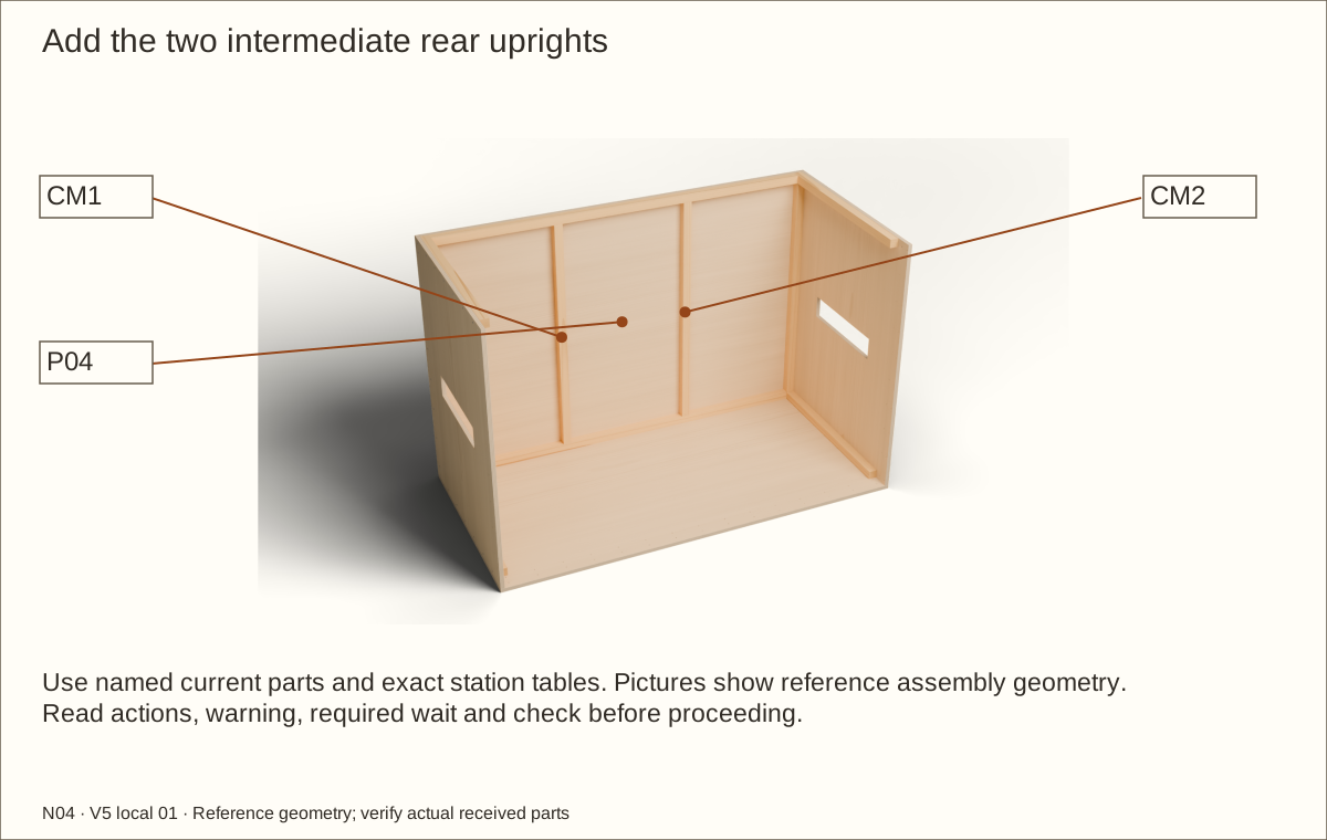
Add the two intermediate rear uprights — 1
Place CM1 and CM2 inside the back with their centres 24 in (609.6 mm) and 48 in (1219.2 mm) from the left outside face. Their ends fit between the lower and upper rear wood supports.
Clamp CM1 and CM2 straight against P04. Transfer their listed hole stations from outside, keeping the scheduled offsets from corner and horizontal-support screws.
Check before continuing: CM1 and CM2 are straight and clamped at their own positions, clear of adjacent screw routes.
Tools / setup: Measuring tape, square, pencil and the tools named below
Add the two intermediate rear uprights — 2
Drill clearance through P04 and stopped pilots into the uprights. Fasten with #8 × 1 1/4 in (31.75 mm) screws; keep the wood beneath the future membrane free from points, splinters and proud heads.
Check each upright bears at both ends and the back remains flat. These members brace the panel; they do not turn the floor into an unsupported span.
Check before continuing: Four rear uprights are in place, with continuous full-floor support still required.
Tools / setup: Measuring tape, square, pencil and the tools named below
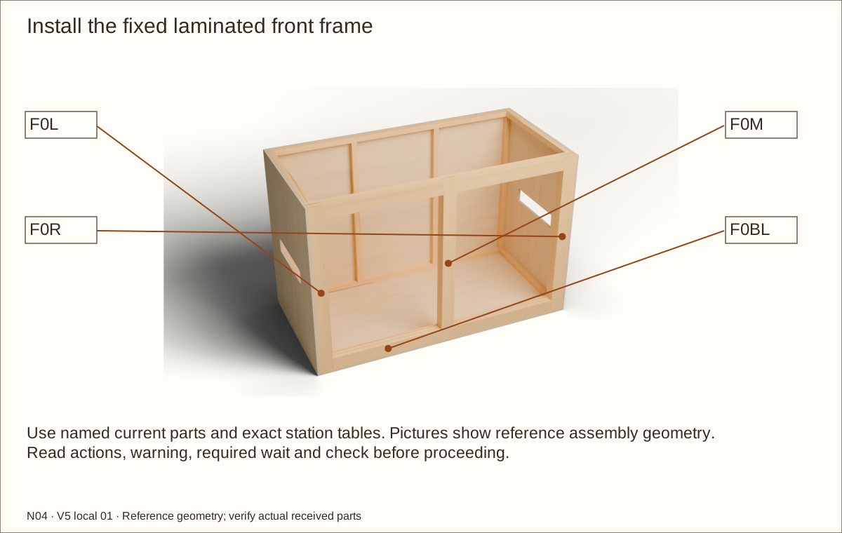
Install the fixed laminated front frame — 1
With a helper, place the cured four-layer frame in its 3 in (76.2 mm) front recess, resting on P01. Keep its outer front face flush with the side-panel fronts; centre the fixed vertical divider.
Clamp the frame and check both bay widths, both diagonals and the top bearing surface. The sides overlap the jamb ends; there is no glue bond between the frame and shell during this trial.
Check before continuing: The cured fixed front sits square and flush with its measured bays and top bearing plane.
Tools / setup: Measuring tape, square, pencil and the tools named below
Install the fixed laminated front frame — 2
Transfer the side stations through P03L/P03R into the full jambs. Use #8 × 2 in (50.8 mm) screws, with clearance through plywood and stopped pilots into pine. Use the scheduled alternating depth lines.
While the empty assembly is safely supported, drill the floor stations from below and fasten into the bottom rail with #8 × 2 in (50.8 mm) screws. Their depth lines differ from the side screws. Return the shell to continuous support and leave the fixed frame installed for the remaining trial.
Check before continuing: The entire front frame is supported, square and attached; the centre vertical divider and kick rail are permanent.
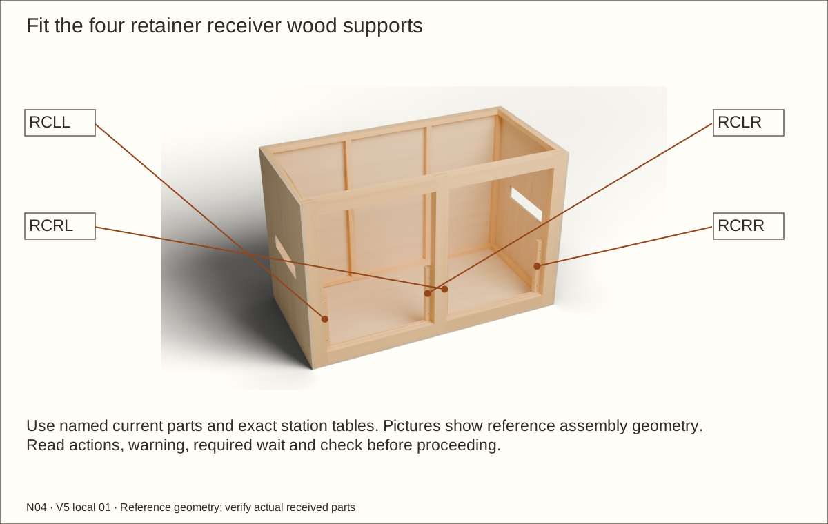
29. Fit the four retainer receiver wood supports — 1
Parts: RCLL, RCLR, RCRL, RCRR
Tools / setup: Measuring tape, square, pencil and the tools named below
Fit the four retainer receiver wood supports — 1
Set RCLL, RCLR, RCRL and RCRR behind the two panel bays, resting on the bottom rail. Their front faces sit directly behind the three plywood layers of the retaining panels; their sides touch the adjoining frame uprights. Receiver fronts begin 2 7/64 in (53.58 mm) behind FRONT at the reference gauge. Keep these hidden contacts flat, sealed and unveneered.
Transfer all four sideways screw stations per receiver. Drill #8 clearance through the receiver only, then a stopped 7/64 in (2.78 mm) trial pilot into the adjoining laminated upright.
Check before continuing: All four receivers bear on the kick rail and their screw and bolt routes remain accessible.
30. Fit the four retainer receiver wood supports — 2
Parts: RCLL, RCLR, RCRL, RCRR
Tools / setup: Measuring tape, square, pencil and the tools named below
Fit the four retainer receiver wood supports — 2
Drive the sixteen #8 × 3 in (76.2 mm) screws sideways into the frame. Each passes through 1 1/2 in (38.1 mm) of receiver and engages about 1 1/2 in (38.1 mm) of frame; do not substitute the shorter shell screws.
Keep these screw heights distinct from the three future bolt heights. Check the receivers are straight, immobile and free of sharp edges before placing either panel.
Check before continuing: Each receiver is fixed with four scheduled screws, and every bolt route remains clear.
Tools / setup: Measuring tape, square, pencil and the tools named below
Before you begin: Never remove any connection when the bed or any water remains. Keep recess depth and washer bearing as specified.
Fit both panels with flush exterior fasteners — 1
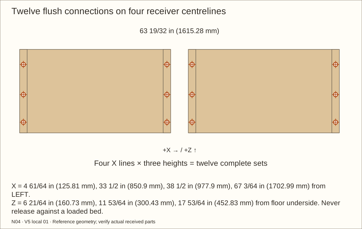
Set both cured panels on the kick rail, front flush and tops 20 in (508 mm) above the finished-floor mark, with 5/32 in (3.97 mm) bare gaps on each side. Clamp flat against the four receivers. Mark X = 4 61/64 in (125.81 mm), 33 1/2 in (850.9 mm), 38 1/2 in (977.9 mm) and 67 3/64 in (1702.99 mm) from the left outside datum; at each X, use Z = 6 21/64 in (160.73 mm), 11 53/64 in (300.43 mm) and 17 53/64 in (452.83 mm) from the floor underside. These heights are 5 1/2 in (139.7 mm), 11 in (279.4 mm) and 17 in (431.8 mm) above the reference finished floor.
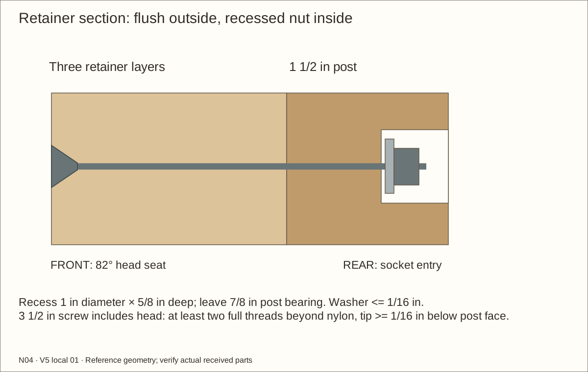
With each loose receiver squarely clamped, make three stopped 1 in (25.4 mm)-diameter flat-bottom recesses from the rear, 5/8 in (15.88 mm) deep. Leave 7/8 in (22.23 mm) receiver thickness at each washer seat. Reassemble and clamp the stack; drill backed 9/32 in (7.14 mm) through bores at the matched centres. Never hold loose stock by hand under the bit.
Check before continuing: The matched recesses and through bores are square; all four receivers retain the scheduled bearing wood.
Tools / setup: Measuring tape, square, pencil and the tools named below
Before you begin: Never remove any connection when the bed or any water remains. Keep recess depth and washer bearing as specified.
Fit both panels with flush exterior fasteners — 2
Countersink only the front plywood for the actual 82° head, flush to bare wood. Preserve a 0.55 in (13.97 mm) veneer service opening at each drive. Insert the twelve 3 1/2 in (88.9 mm) machine screws from the front; fit one washer and nylon nut inside each rear recess. Trial the actual 7/16 in (11.11 mm) socket, outside diameter at most 7/8 in (22.23 mm), and a 5/32 in (3.97 mm) hex driver before lining.
Hand-tighten evenly without crushing wood or forcing seized stainless threads. Require two complete threads beyond nylon and at least 1/16 in (1.59 mm) screw-tip cover beneath the receiver rear face. Do not deepen recesses, omit washers or shorten wrong screws. Withdraw screws outward for removal; all twelve complete sets stay installed whenever contents or water remain.
Check before continuing: All twelve flush heads are accessible; complete recessed nut stacks have two exposed threads and covered rear tips.
Tools / setup: Measuring tape, square, pencil and the tools named below
Fit the unglazed doors to their actual bays — 1
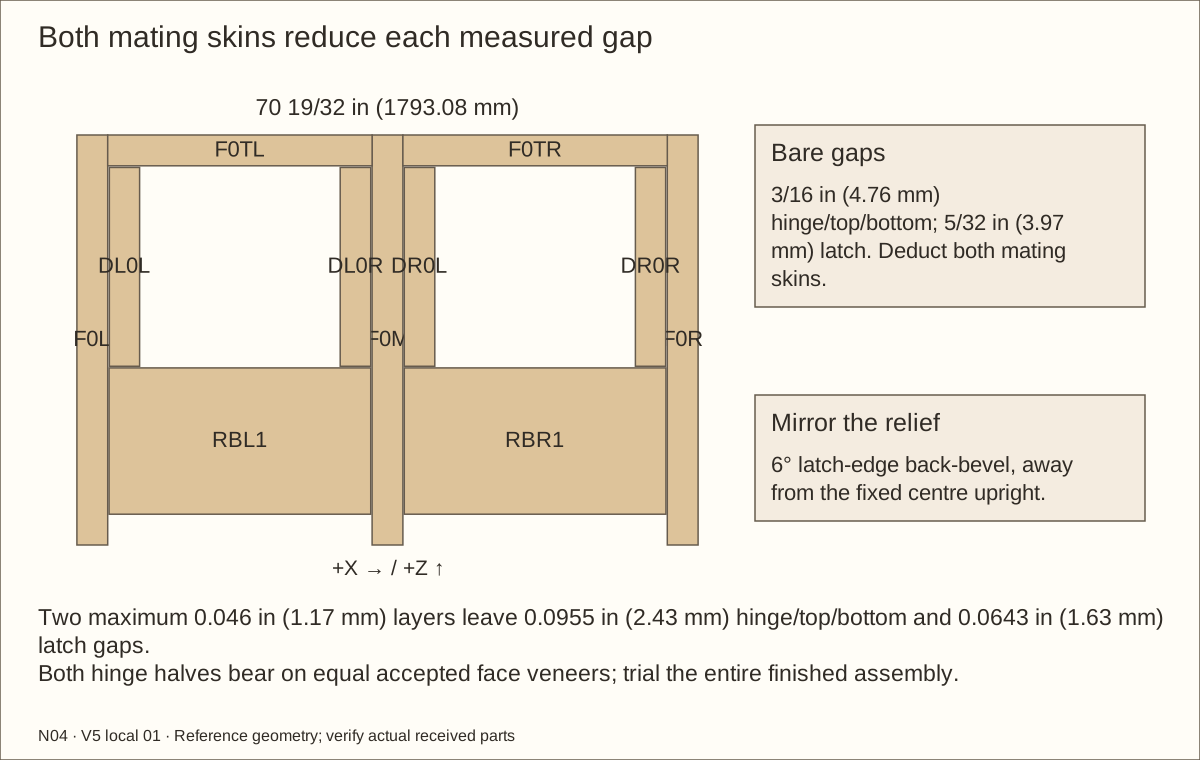
Fit each cured leaf flush in its own marked bay. Use 3/16 in (4.76 mm) bare hinge/top/bottom gaps and 5/32 in (3.97 mm) bare latch gap. Two 0.0305 in (0.77 mm) opposing skins leave 0.1265 in (3.21 mm) and 0.0953 in (2.42 mm); two maximum 0.046 in (1.17 mm) skins leave 0.0955 in (2.43 mm) and 0.0643 in (1.63 mm). Record actual cured gaps and recalculate for changed layers.
Correct unequal diagonals before trimming. Back-bevel only each latch edge 6° away from the centre divider, retaining its front-edge position. This means the rear edge is narrower for swing clearance. Mirror the bevel on the right leaf and preserve all rear glazing datums.
Check before continuing: The reference and actual finished gaps are recorded; the viewing opening and rear pocket remain unchanged.
Tools / setup: Measuring tape, square, pencil and the tools named below
Fit the unglazed doors to their actual bays — 2
Check the rear glazing spacers and beads against the door’s wider uprights. Their wood must remain outside the pane pocket; no bead screw may pass through a pane edge or its expansion gap.
Mark each door and bay as a pair. Remove temporary spacers only when the hinges and a helper support the leaf. Acrylic remains out during this fitting stage.
Check before continuing: The reference and actual finished gaps are recorded; the viewing opening and rear pocket remain unchanged.
Tools / setup: Supported router jig, depth stop, actual wire and cured film sample
Before you begin: Qualify the actual cut wire edges and coating before assembly.
Route the side-capture wire pockets
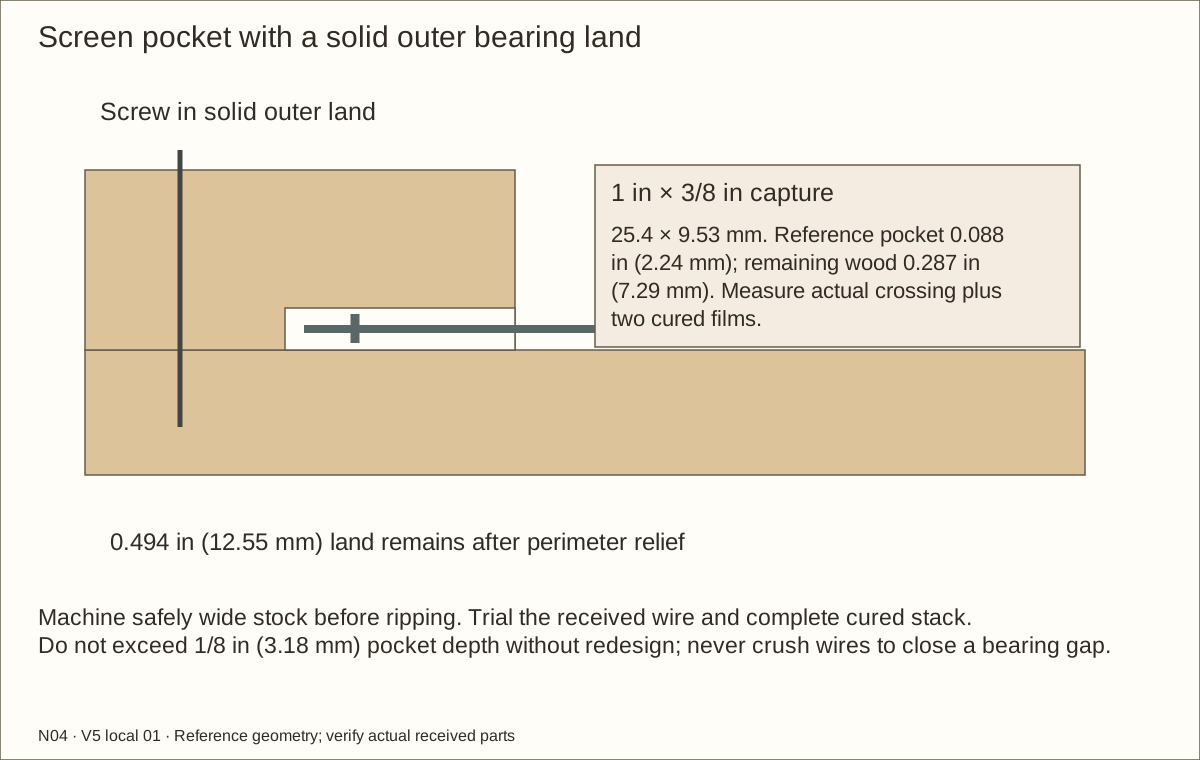
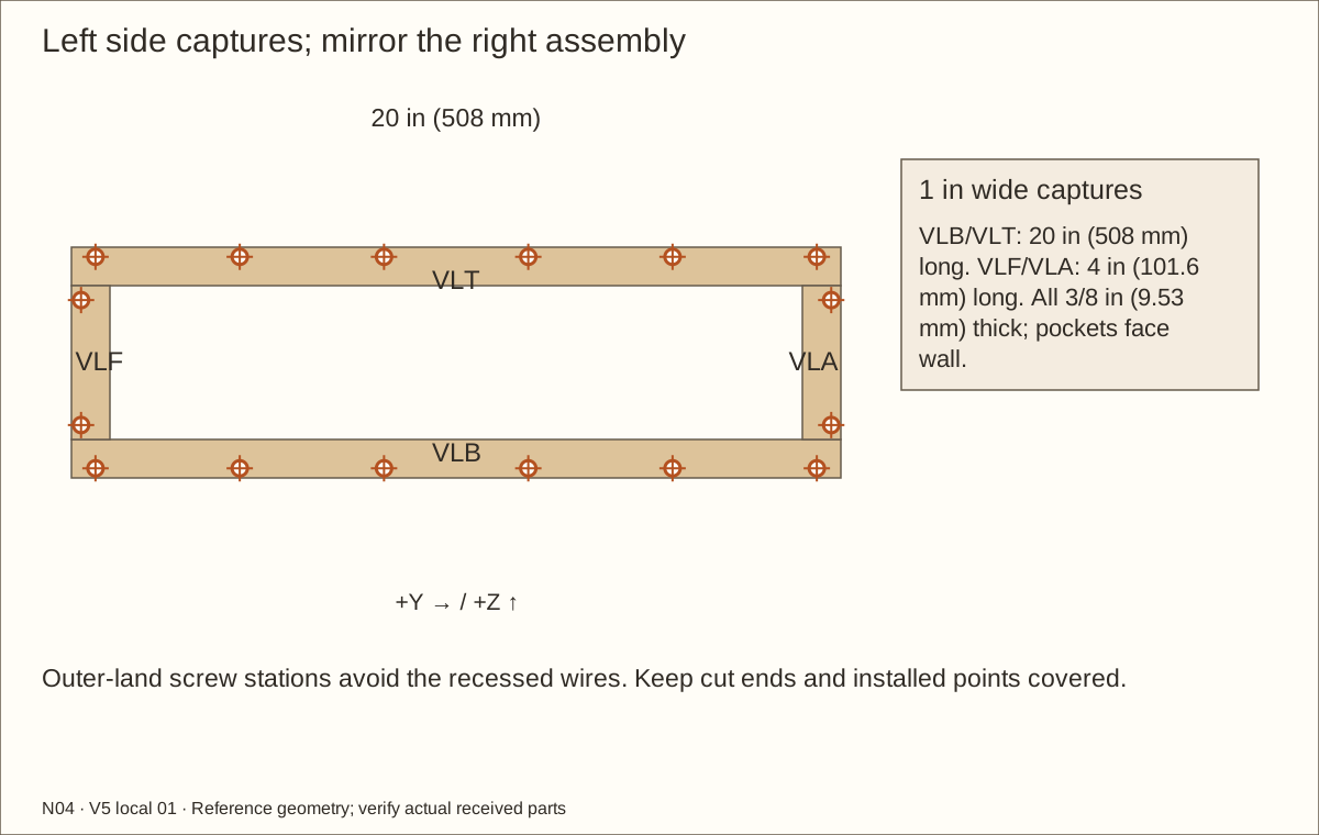
On the broad 3/8 in (9.53 mm) capture stock, lay out the pocket and separate outside bearing land. Route the wall-facing rebate with a supported guide and depth stop; do not hand-hold a loose narrow piece. Reference depth is 0.088 in (2.24 mm) for 0.082 in (2.08 mm) crossing wire plus 0.006 in (0.15 mm) cured films.
Trial the actual wire and film. Each widened 1 in (25.4 mm) capture must lie flat on its solid 0.494 in (12.55 mm) reference outer land, enclosing every cut wire end. The rebate cannot exceed 1/8 in (3.18 mm) without redesign. Drill screws through the separate land, never through wire.
Check before continuing: Capture bears flat; wire and screw paths are separate.
Tools / setup: Measuring tape, square, pencil and the tools named below
Capture the two side-vent meshes — 1
Cut two 19 in (482.6 mm) × 5 in (127 mm) mesh blanks with protected hands and snips. Flatten the edges and remove loose wire ends; do not leave a burr pointing into the enclosure.
Centre each blank over its vent from outside, giving 1/2 in (12.7 mm) overlap around the opening. Set the lower and upper capture strips, then the end strips between them. Use widened 1 in (25.4 mm) captures with 0.088 in (2.24 mm) reference wall-facing wire rebates and 0.494 in (12.55 mm) solid outer bearing lands. Trial the received crossing and cured film; no veneer lies beneath capture bearing.
Check before continuing: Every cut side-wire edge stays inside its capture pocket and the solid outer lands bear on wood.
Tools / setup: Measuring tape, square, pencil and the tools named below
Capture the two side-vent meshes — 2
Use scheduled revised outer-land stations clear of wire. Clearance-drill captures, stop #6 pilots in the wall and fit #6 × 1 in (25.4 mm) screws flush with bare wood, with accessible veneer drive openings and at least 1/16 in (1.59 mm) interior tip cover.
Inspect the entire captured perimeter. No wire end should be reachable through the inner opening or pull free when checked by hand. A smaller containment mesh opening, if required later, needs its own retained mounting and ventilation review.
Check before continuing: Both meshes are mechanically captured and the inner wood reveals are smooth.
Tools / setup: Supported router jig, depth stop and sample
Route the roof-capture wire pockets
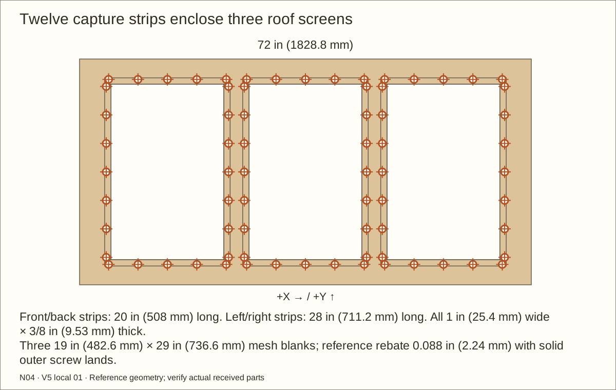
Use the same accepted wire/cured-film sample to fit all twelve roof captures. Cut a 0.088 in (2.24 mm) reference roof-facing rebate, preserving the 0.494 in (12.55 mm) outer bearing land and at least 1/4 in (6.35 mm) wood beneath the pocket.
Machine with broad stock and safe supported stops before cutting narrow final lengths. Dry-seat the three complete 19 in (482.6 mm) × 29 in (736.6 mm) wire blanks and verify all four captures bear on roof wood without rocking.
Check before continuing: Entire wire perimeter is enclosed and the solid outer lands touch P02.
Tools / setup: Measuring tape, square, pencil and the tools named below
Build the removable screened roof — 1
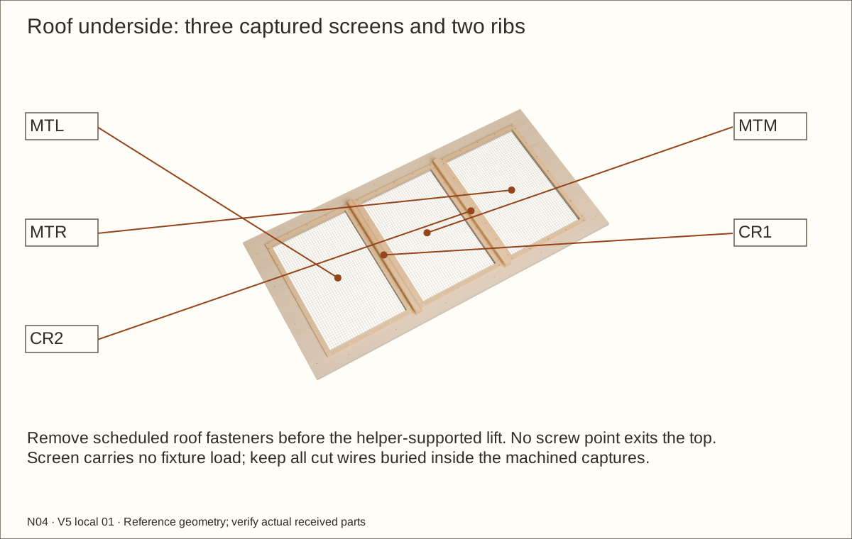
Lay P02 upside down on a padded bench. Centre three 19 in (482.6 mm) × 29 in (736.6 mm) mesh blanks over the roof openings, keeping 1/2 in (12.7 mm) edge overlap.
Fit twelve widened captures around the three openings, with 0.088 in (2.24 mm) roof-facing rebates for the 0.082 in (2.08 mm) two-wire crossing plus 0.006 in (0.15 mm) reference films. Solid outer lands bear on P02; use scheduled #6 × 1 in (25.4 mm) outer-land screws. Do not force strips over wire or pierce the roof face.
Check before continuing: All three roof meshes and twelve captures fit flat; both solid roof webs and rib routes remain intact.
Tools / setup: Measuring tape, square, pencil and the tools named below
Build the removable screened roof — 2
Fit CR1 and CR2 beneath the two solid webs, centred at 25 in (635 mm) and 47 in (1193.8 mm) from the left. Drill from the roof top and fit #8 × 1 1/4 in (31.75 mm) screws into the ribs.
Check the roof fits on the fixed front frame, side upper wood supports and rear upper wood support. Transfer its attachment stations, then set it aside for finishing. Screens carry no light fixture, climbing or lifting load.
Check before continuing: Both ribs remain under solid webs; every mesh edge is captured and the roof remains removable.
Tools / setup: Measuring tape, square, pencil and the tools named below
Before you begin: Support the leaf with a helper whenever a hinge is being fitted or released.
Hang both doors on true lift-off hinges — 1
Support each leaf at its scheduled gaps using equal fully cured veneer coupons beneath fixed and moving hinge leaves. Keep original hinge join centres at Z = 24 29/64 in (621.11 mm), 32 5/16 in (820.74 mm) and 40 11/64 in (1020.37 mm) from the floor underside. These absolute positions remain after trimming; do not remeasure from new door ends. Align three axes per side.
Use the received hinge as the hole template. Its fixed lower pin half mounts on the jamb and its upper removable socket mounts on the door. In this guide the left jamb uses LSX-100R and the right LSX-100L, confirmed by the manufacturer’s fixed-half orientation.
Check before continuing: All three marked axes on each door align; equal accepted cured coupons reproduce the intended final mounting plane.
Tools / setup: Measuring tape, square, pencil and the tools named below
Before you begin: Support the leaf with a helper whenever a hinge is being fitted or released.
Hang both doors on true lift-off hinges — 2
Transfer all six actual holes per hinge on the accepted trial coupons. Drill stopped #6 pilots and fit #6 × 1 1/4 in (31.75 mm) screws. At final assembly replace coupons with continuous accepted cured face veneer beneath both hinge leaves; reference axis is 0.3061 in (7.77 mm) ahead of bare FRONT. Prove head seating and stable full bearing before proceeding.
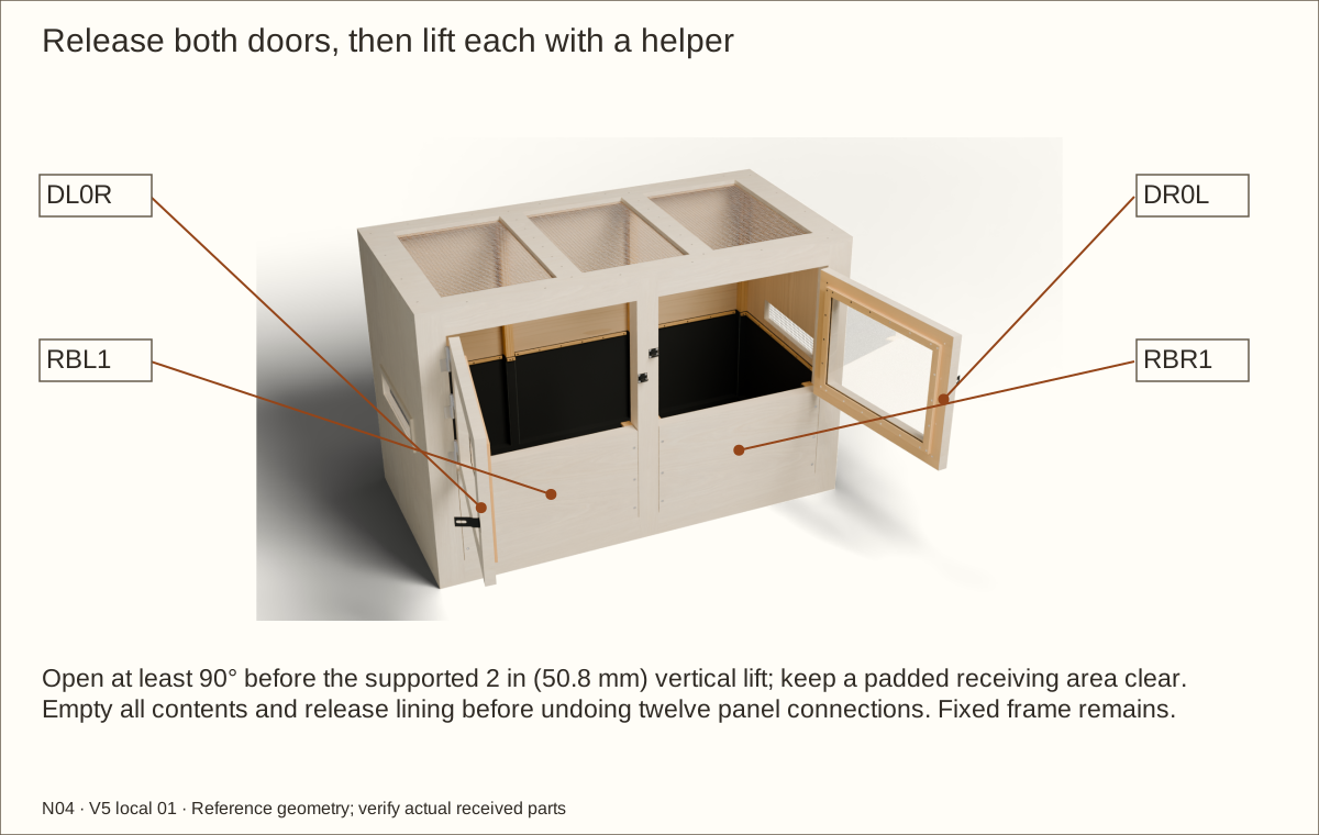
Remove the spacers while supporting the leaf. Slowly swing to 100°, checking the jamb, centre vertical divider, retainer top and rear beads. At 90° or more, support and lift 2 in (50.8 mm) to clear the pins, then refit all three sockets together. Stop and correct misalignment or binding.
Check before continuing: All three axes on each door align; supported full swing and two-inch lift-off work without binding.
Parts: Complete enclosure, support and received inventory, as described below
Tools / setup: Measuring tape, square, pencil and the tools named below
Rehearse the empty cleaning route — 1
With the enclosure empty, lift off both doors and set them on padded supports. Remove the roof using a helper; do not use mesh as a handle.
After removing every bit of contents and water, remove lining clamps in reverse installation order and fold the empty liner/underlay clear. Support each panel, hold its front hex drives and remove recessed interior nuts/washers. Withdraw twelve screws outward, then draw panels forward. Keep the centre divider, fixed frame and kick rail attached.
Check before continuing: Supported doors, empty lining and both retainers can be removed while the permanent shell stays on its qualified support.
Parts: Complete enclosure, support and received inventory, as described below
Tools / setup: Measuring tape, square, pencil and the tools named below
Rehearse the empty cleaning route — 2
Each bare service bay is 30 3/64 in (763.19 mm) wide; opposing maximum skins leave 29.9549 in (760.85 mm). Fixed kick-rail height is 3 3/8 in (85.73 mm) above the finished-floor reference. Trial the actual cleaning tools and containers through both bays and around all rear posts.
Dry-fold liner and underlay blanks through the front corners and rear uprights. Confirm slack at every change of direction, space for the front clamps and a route to lift out the complete empty basin. Refit and tighten both retaining panels before continuing.
Check before continuing: The entire empty base can be serviced without removing the fixed frame or moving a loaded enclosure.
Parts: Complete enclosure, support and received inventory, as described below
Tools / setup: Measuring tape, square, pencil and the tools named below
Prepare and fully finish the wood — 1
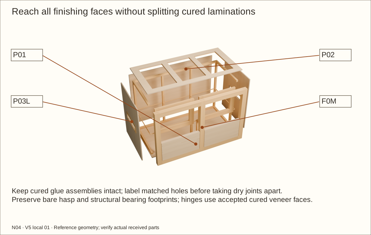
Label and remove hardware, doors, retainers, roof, meshes and lining. Disassemble the dry-fitted shell as needed to reach all wood faces. Keep the cured glued assemblies intact and protect every screw location.
Ease edges, remove dust and repair damage. Keep structural receiver/bottom bearing faces sealed and flat. Do not fill intentional stopped nut recesses, service drives or pilots. Preserve future glue faces and bare hasp footprints; accepted hinge bearing faces receive continuous cured veneer.
Check before continuing: Removed parts are labeled, surfaces repaired and cleaned, and protected bearings and drives marked.
Parts: Complete enclosure, support and received inventory, as described below
Tools / setup: Measuring tape, square, pencil and the tools named below
Prepare and fully finish the wood — 2
Apply the current Varathane Triple Thick satin label to exposed wood and the supplier-approved presealed veneer substrate. Upper one-coat planning area is 523.51 sq ft (48.64 m²), including rectangular faces, veneer topcoat, trial and contingency. Buy 6 two-can packs of US quart (0.946 L) cans. Added coats or balancing layers need recalculation.
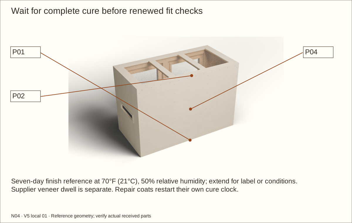
Allow the full seven-day cure at the manufacturer’s stated 70°F (21°C) and 50% relative humidity reference conditions, longer when the label or conditions require. Handle and recoat only at the permitted times. An odor check or surface dryness does not replace full cure.
Check before continuing: All wood, cut reveals and protected below-liner surfaces are covered and fully cured.
Required wait: Finish: seven days full cure at stated reference conditions; extend as required
Parts: Complete enclosure, support and received inventory, as described below
Tools / setup: Measuring tape, square, pencil and the tools named below
Before you begin: Do not substitute an unapproved adhesive or balancing system.
Approve and label the full exterior veneer
Choose one species for the entire enclosure: maple, white oak or walnut. Obtain written supplier acceptance for the backing/PSA, balance of each panel, actual cured substrate, service temperature/humidity and cleaners. The preview textures are appearance references, not a delivered grain sample.
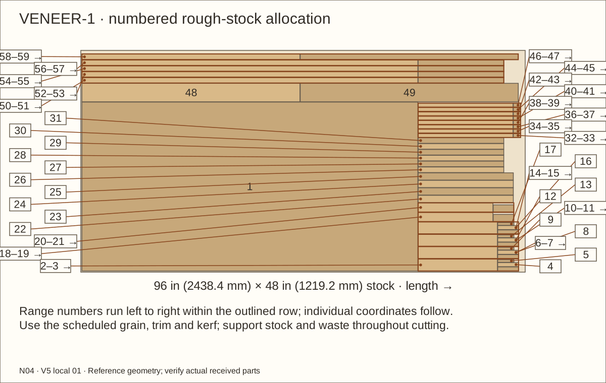
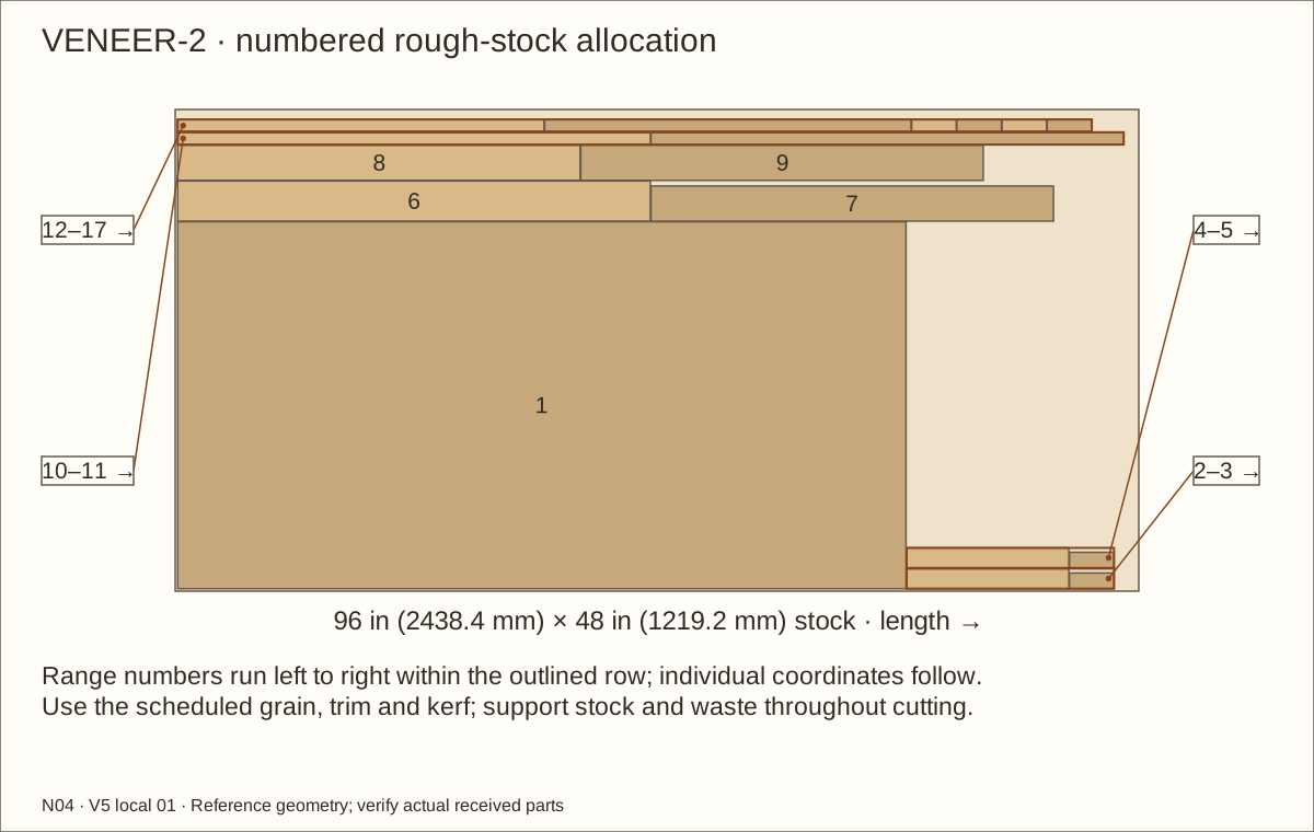
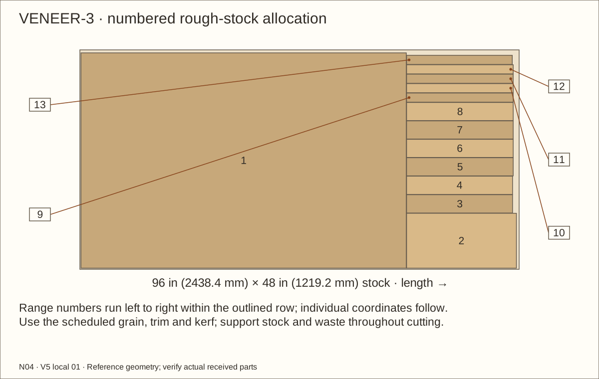
Use the veneer layouts to rough-cut labeled faces and edge/reveal strips with grain in their scheduled direction. The reference whole skin is 0.0305 in (0.77 mm) and the maximum coordinated skin is 0.046 in (1.17 mm). Measure actual cured samples; a thicker system requires new dimensions and motion checks.
Check before continuing: The selected whole system and actual thickness are accepted before sticking any full sheet.
48. Apply the skins without bridging removable parts
Parts: Complete enclosure, support and received inventory, as described below
Tools / setup: Measuring tape, square, pencil and the tools named below
Apply the skins without bridging removable parts
Acclimate and prepare the veneer and sealed substrate for the supplier’s written conditions. Follow its pressure tool, application sequence and full bond-development wait. Retain that required duration in the receiving record; this guide does not invent one. Start with a matching offcut sample and inspect bond and balance first.
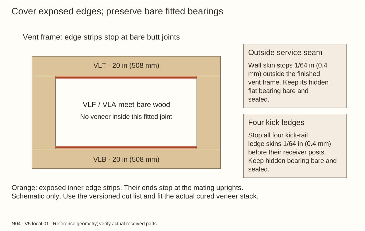
Apply each scheduled exterior face, roof surface, exposed edge and reveal separately. Stop vent edge bands at bare butt joints; fit the wall skin 1/64 in (0.4 mm) outside the finished vent-frame perimeter. Stop the four kick-rail ledge skins 1/64 in (0.4 mm) before their receivers, leaving hidden bearings bare. Keep the retainer underside and receiver-contact faces bare and sealed; preserve all service seams, traced bare hasp footprints and 0.55 in (13.97 mm) retainer-drive openings. Trim with a supported straightedge and sharp tool without rounding the reference mating edge.
Check before continuing: All exposed plywood edges are covered, while joints, bearing seats and drives stay accessible.
Required wait: Supplier-specified acclimation, pressure and full bond-development wait; unresolved H03 must be closed first.
Parts: Complete enclosure, support and received inventory, as described below
Tools / setup: Measuring tape, square, pencil and the tools named below
Topcoat and fully cure the completed veneer
Apply only the supplier-accepted clear finish to the completed veneer, exposed edges and reveals. Keep bare hasp seats, drives and future bond faces masked; hinge bearing faces retain the accepted continuous cured veneer. Follow the actual label temperature, humidity, recoat and handling limits.
Allow the Varathane full seven-day cure at 70°F (21°C) and 50% relative humidity, or longer if the label/conditions require, before renewed assembly tests. Surface dryness or lack of smell is not proof of cure. Check the sample bond, panel flatness and actual completed skin again.
Check before continuing: All finishes are fully cured and the accepted actual veneer stack remains within the coordinated allowance.
Required wait: At least seven days full finish cure at stated reference conditions; extend as required.
Parts: Complete enclosure, support and received inventory, as described below
Tools / setup: Measuring tape, square, pencil and the tools named below
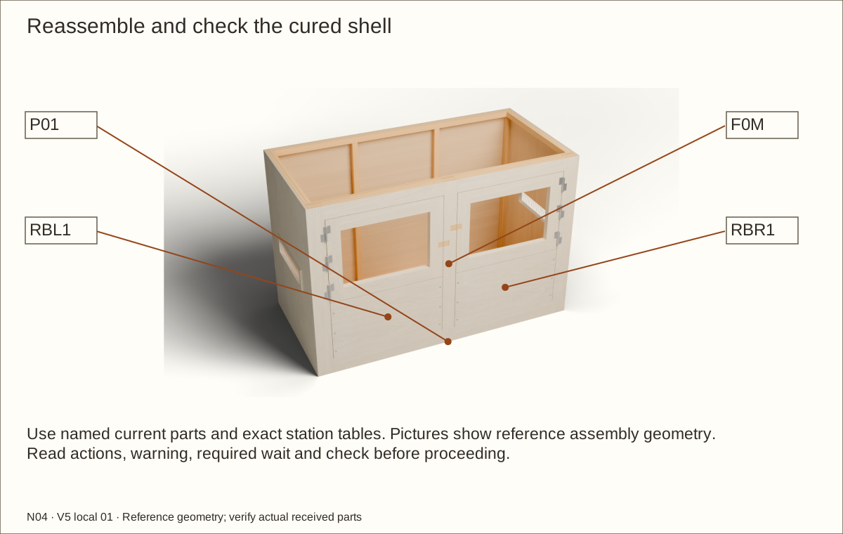
Reassemble and check the cured shell — 1
Refit the floor, sides, back, rear uprights and fixed front frame to their labeled holes. Hand-tighten the scheduled screws, checking their seating and covered tips; replace a damaged receiver properly rather than using an arbitrary longer screw.
Refit all four receivers and both panels with twelve complete flush screw/washer/recessed-nut sets. Recheck two full threads, covered tails, accessible front drives, flat bearing and diagonals on the permanent support. Protect every rear recess with loose supplementary underlay before lining.
Check before continuing: The reassembled shell and all twelve retainer connections are square and accessible without crushing wood.
Parts: Complete enclosure, support and received inventory, as described below
Tools / setup: Measuring tape, square, pencil and the tools named below
Reassemble and check the cured shell — 2
Refit the side mesh and roof mesh assemblies. Rehang the unglazed doors and repeat full swing, removal and refitting after the finish has changed the surfaces. Do not scrape or force cured mating faces into place. Repeat with actual cured veneer, mirrored latch bevels and retainer-top gaps. Any exposed wood after adjustment needs resealing and full recure.
Remove both supported doors and the roof again for lining. Keep all twelve complete connections installed. Smooth and pad the stopped rear nut pockets and all hard corners; protect the membrane without creating unsupported folds.
Check before continuing: The cured shell is square and mechanically complete, with clear door motion and a smooth basin backing.
Tools / setup: Measuring tape, square, pencil and the tools named below
Before you begin: Never cut, drill or staple below the upper dry clamping band. The shallow observation is not a load test.
Fit and test the continuous basin — 1
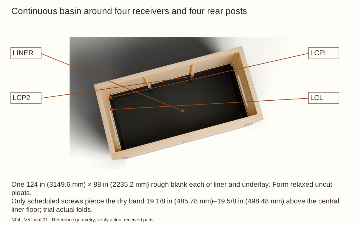
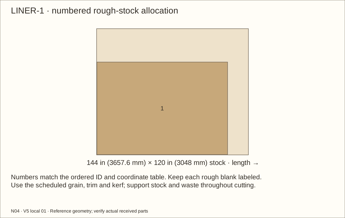
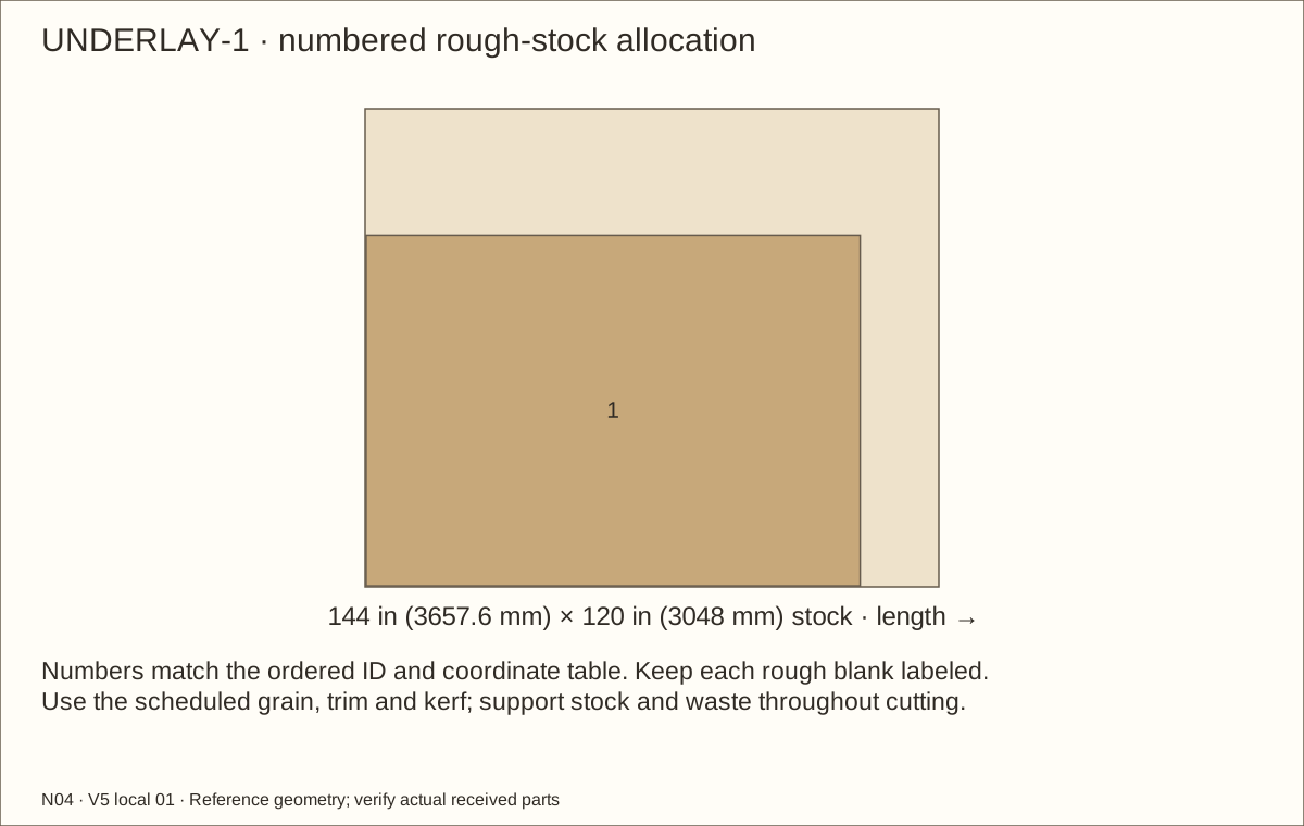
Cut one 124 in (3149.6 mm) × 88 in (2235.2 mm) blank each of underlay and EPDM from the exact 120 in (3048 mm) × 144 in (3657.6 mm) stock. Orient the long cut along the stock’s 144 in (3657.6 mm) length. Dry-fold first; do not trim away a corner to make it lie flat.
Lay underlay, then liner, across the central floor and over the raised bottom supports. Form relaxed folds around the four front receiver wood supports, fixed front uprights and four rear uprights. Leave slack at each inside corner; no membrane should bridge a sharp edge or stretch across a unsupported pocket.
Check before continuing: Underlay covers every hard contact; the relaxed uncut basin fits all eleven post returns without unsupported folds.
Tools / setup: Measuring tape, square, pencil and the tools named below
Before you begin: Never cut, drill or staple below the upper dry clamping band. The shallow observation is not a load test.
Fit and test the continuous basin — 2
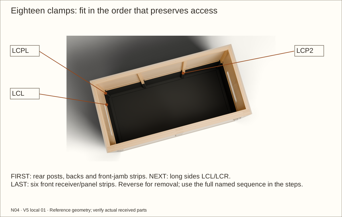
Dry-fit all eighteen rounded clamps with screw centers 19 3/8 in (492.13 mm) and liner top 19 3/4 in (501.65 mm) above the central lined floor, clear of the 18 in (457.2 mm) total bed. Fit LCPL/LCP1/LCP2/LCPR, then LCB1/LCB2/LCB3 and LCFJ1/LCFJM/LCFJ2, then LCL/LCR, then LCFRL/LCFPL/LCFRM/LCFML/LCFPR/LCFRR. Only the 66 scheduled screws may pierce the dry band from 19 1/8 in (485.78 mm) to 19 5/8 in (498.48 mm) above that floor. Predrill and deburr wood with the membrane removed. Refit relaxed folds and press each screw through its planned membrane station by hand before tightening. Never wind loose rubber around a drill bit. Reverse the order for removal; trim only above the final top line.
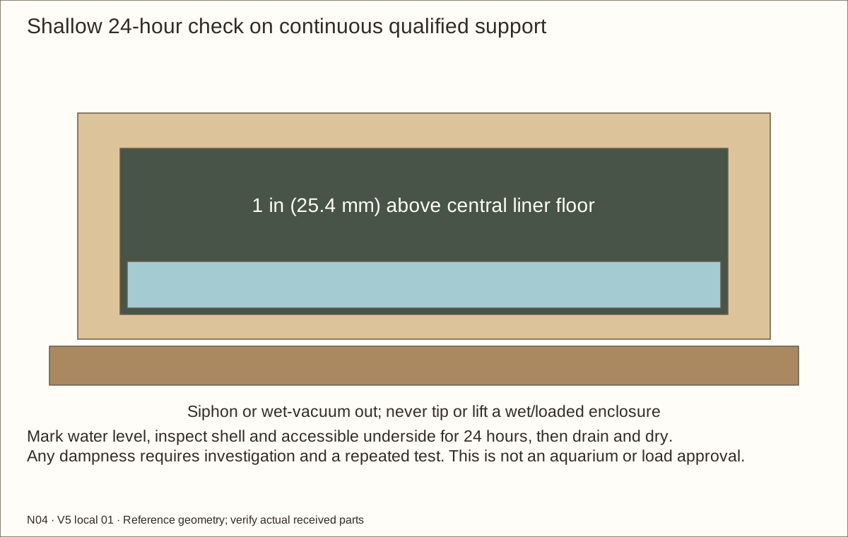
With all clamps and twelve retainer connections installed and the floor supported, add only 1 in (25.4 mm) of water for a 24-hour shallow seam-and-fold observation. Inspect accessible wood and the underside for leakage without moving the shell. Siphon or wet-vacuum the water, dry completely and correct any leak before filling. This shallow check is not a full-depth tank or structural test.
Check before continuing: All sixty-six clamp screws are confined to the dry band. The shallow observation is complete without visible leakage; the basin has been drained and dried.
Required wait: Shallow liner observation: 24 hours, followed by complete draining and drying.
Tools / setup: Measuring tape, square, pencil and the tools named below
Before you begin: Do not drill, glue, squeeze or rigidly trap the acrylic.
Cut and retain the floating acrylic panes — 1
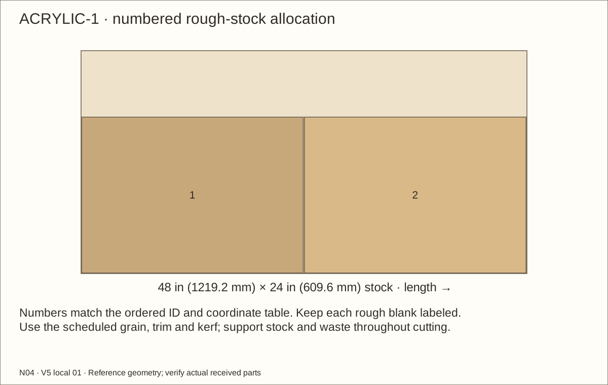
Measure both cured pockets and the actual sheet. Each reference acrylic pane is 23 51/64 in (604.44 mm) wide × 16 23/32 in (424.66 mm) high × 0.22 in (5.59 mm) thick. Both fit one 24 in (609.6 mm) × 48 in (1219.2 mm) sheet with the specified 1/16 in (1.59 mm) rough allowance per dimension, 1/16 in (1.59 mm) perimeter trim and 1/8 in (3.18 mm) kerf. Use the layout and acrylic maker’s supported cutting method; retain masking through edge finishing.
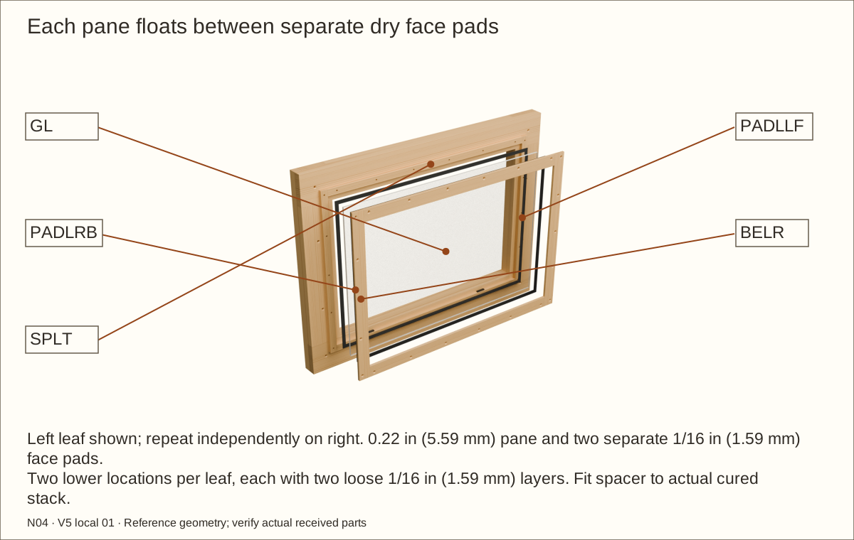
Fit spacers and two lower setting pads in each frame. The pocket is 1/4 in (6.35 mm) larger than the pane in width and height; centre the pane with 1/8 in (3.18 mm) at each side and top. The lower 1/8 in (3.18 mm) gap holds the two-layer setting pads. Keep the pane free to move as temperature changes. Each lower setting location stacks two loose 1/16 in (1.59 mm) neoprene layers; no adhesive or assumed compression. Keep four locations distinct across the two doors.
Check before continuing: Actual pane and pads are measured and fitted to the cured pocket with open edge allowance.
Tools / setup: Measuring tape, square, pencil and the tools named below
Before you begin: Do not drill, glue, squeeze or rigidly trap the acrylic.
Cut and retain the floating acrylic panes — 2
Fit separate dry front/rear pads and rear beads. Include actual cured films when fitting 0.351 in (8.92 mm) reference bare spacers from 3/8 in (9.53 mm) rough stock. Beads seat on spacer wood. Drill bead/spacer clearance and stopped wood pilots outside the pane and its movement space.
Use #8 × 1 1/4 in (31.75 mm) bead screws, tightening only until beads seat on spacers. Do not squeeze the pane, drill it, glue it into the pocket or fill its movement gap. Remove masking, clean with an acrylic-compatible method and inspect for cracks, bowing and free expansion space.
Check before continuing: The pane floats with edge clearance and beads seat on wood without squeezing it.
Tools / setup: Measuring tape, square, pencil and the tools named below
Before you begin: Do not drill, glue, squeeze or rigidly trap the acrylic.
Cut and retain the floating acrylic panes — 3
Weigh each complete finished leaf; the independent rectangular-volume estimate is 17.76 lb (8.06 kg) per leaf including veneer and an allowance for hardware/pads/coating. Rehang with a helper and repeat swing, sag, closure and lift-off. Catalogue capacity does not rate this wooden assembly.
Check before continuing: The finished leaf is weighed and passes supported operation and removal checks.
Tools / setup: Measuring tape, square, pencil and the tools named below
Fit the independent door closures — 1
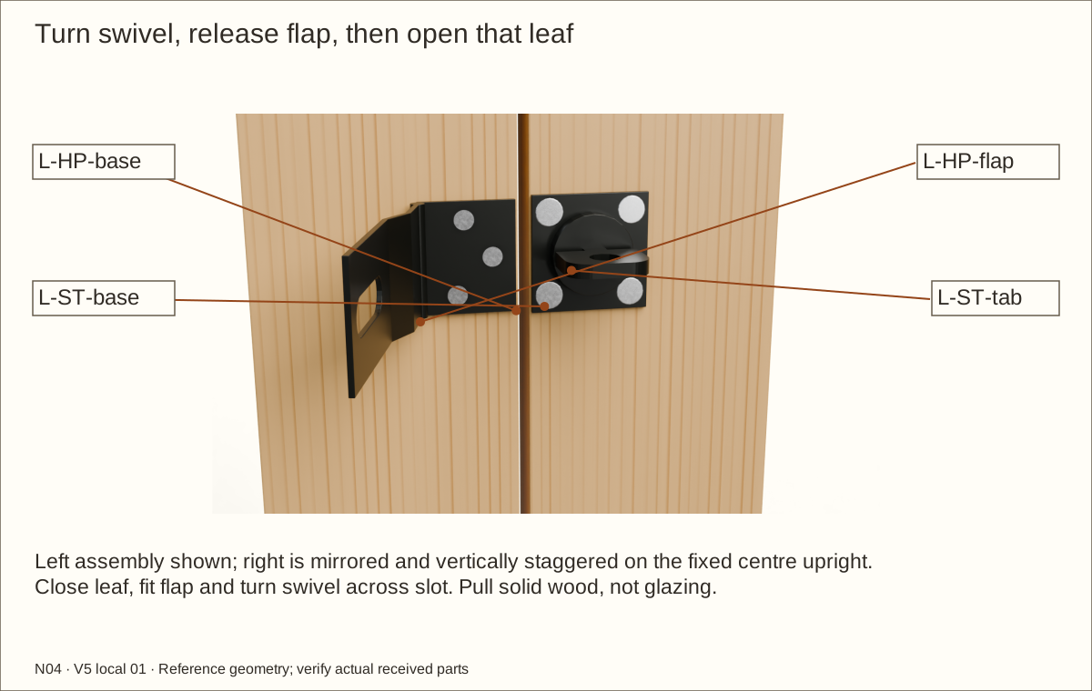
Fit the complete left hasp at Z = 30 5/16 in (769.94 mm) and right at Z = 34 5/16 in (871.54 mm), on the moving latch stiles and fixed centre upright F0M. Rigidly shift the left nominal assembly 5/32 in (3.97 mm) left and right assembly 5/32 in (3.97 mm) right for full plate bearing on the trimmed leaves; actual hardware and slot reach control marking.
Place each hinged base on its moving latch upright and the swivel-staple plate on the fixed vertical divider. Transfer the actual seven holes only after the slot, hinge and swivel operate freely. The model’s formed hardware is an illustration, not a drilling template.
Check before continuing: Both actual hasps have full bearing, accepted screw seating and free slot engagement.
Tools / setup: Measuring tape, square, pencil and the tools named below
Fit the independent door closures — 2
Use the fourteen #10 × 5/8 in (15.88 mm) screws: clearance through the supplied plate holes and stopped pilots into solid wood. Keep at least 1/16 in (1.59 mm) wood behind each tip and all heads seated without distorting the hardware.
For daily operation, align the swivel with the slot, lift the flap and open that door. To secure, close the door, place the flap over the staple and turn the swivel across the slot. Check each closure independently; optional padlocks are not part of the illustrated keyless system. Grip the solid inner edge of the latch upright ahead of the recessed pane to pull the released door open; do not pull on the glazing.
Check before continuing: Each door stays closed when pulled gently and opens only after its own hasp is released.
Tools / setup: Measuring tape, square, pencil and the tools named below
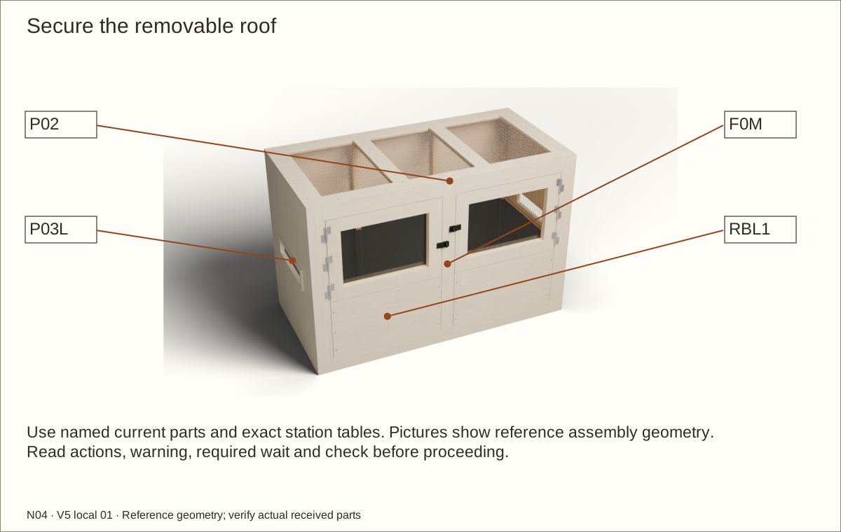
Secure the removable roof — 1
Verify the basin clamps, retained glazing, mesh and closures before placing the roof. With a helper, lower it onto the fixed front frame, both side wood supports and CT without trapping the liner or a cable.
Transfer the roof stations: four per side, six at the front and six at the back. Drill clearance through P02 and stopped pilots into the named receiver.
Check before continuing: Scheduled roof clearance and stopped pilot stations align with their receiving supports.
Tools / setup: Measuring tape, square, pencil and the tools named below
Secure the removable roof — 2
Install #8 × 1 1/4 in (31.75 mm) screws and tighten evenly by hand. Do not glue the roof. Recheck both door gaps and closure operation with the completed shell secured.
Keep screw heads reachable in the eventual equipment arrangement. Disconnect and independently support equipment before roof removal; never lift by the mesh.
Check before continuing: The roof cannot shift or lift unintentionally and both doors retain their correct fit.
Parts: Complete enclosure, support and received inventory, as described below
Tools / setup: Measuring tape, square, pencil and the tools named below
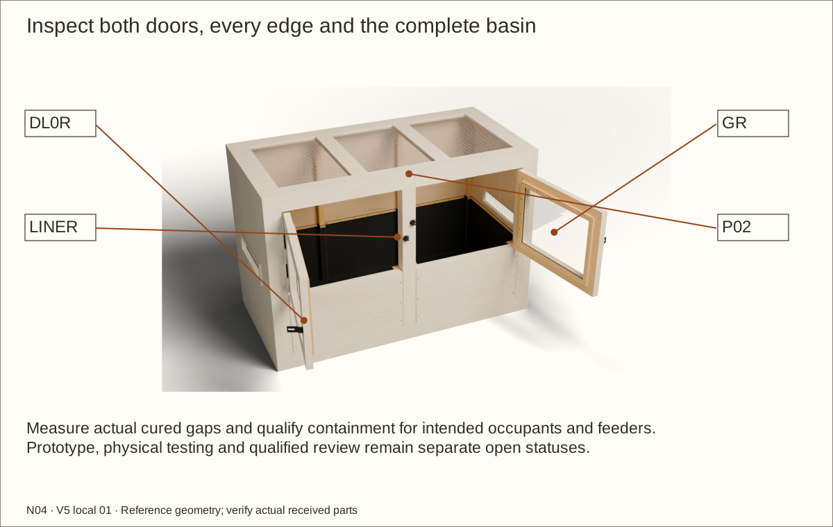
Complete the construction inspection — 1
Check every screw station, all twelve retainer bolt stacks, all six hinge assemblies, both hasps, all glazing beads, all eighteen liner clamps and every mesh edge. Repair splits, burrs, stripped receivers, loose joints and exposed tips.
Measure actual cured gaps around both doors, panels, roof and openings. Scheduled construction clearances and 1/2 in (12.7 mm) mesh do not establish occupant or feeder containment. Recheck after roof fixing and qualified controlled loading.
Check before continuing: All fasteners, screens and actual cured gaps have been inspected and recorded.
Parts: Complete enclosure, support and received inventory, as described below
Tools / setup: Measuring tape, square, pencil and the tools named below
Complete the construction inspection — 2
Verify full finish cure and a dry shell beneath the shallow-tested liner. Confirm no screw, cable or drain penetrates the wet basin, and that every above-fill clamp can be accessed.
Rehearse supported glazed-door lift-off, refitting and secure closure. Confirm the panels’ removal sequence is understood: animals and equipment out, all contents and liquid removed, liner folded clear, then bolts and panels. Record actual finished dimensions and leaf weights. All twelve machine screws withdraw forward after the recessed nuts and washers are removed; never release a connection against loaded substrate or water.
Check before continuing: The completed construction record contains no unresolved defect; animal commissioning remains separate.
Tools / setup: Measuring tape, square, pencil and the tools named below
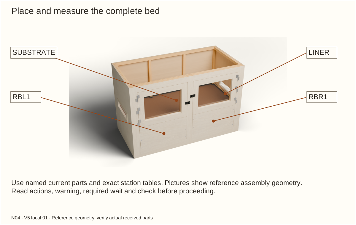
Place and measure the complete bed — 1
Place all permanent support and stability provisions before loading. Protect the membrane beneath hard furnishings with smooth load-spreading pads; never drag rocks or sharp tools over it.
Measure the entire bed from the finished central liner floor. Drainage, separators and substrate together must stay within 18 in (457.2 mm). For example, 2 in (50.8 mm) of drainage leaves at most 16 in (406.4 mm) for the other layers.
Check before continuing: The combined bed stays within its eighteen-inch limit; support and furnishings are secure.
Tools / setup: Measuring tape, square, pencil and the tools named below
Place and measure the complete bed — 2
The conservative uninterrupted floor rectangle is about 67 3/8 in (1711.33 mm) × 29 15/16 in (760.41 mm), or 14.00 sq ft (1.30 m²). Above the full bed, about 27 in (685.8 mm) remains below the lowest upper supports before fixtures and furnishings are deducted.
Weigh the actual wet mix and record the installed total load. Watch for support deflection, changed door gaps, joint movement and liner damage during filling. Stop and unload if anything shifts. The density calculations are planning scenarios, not permission to load an unqualified stand or floor.
Check before continuing: The complete bed stays below its line with 2 in (50.8 mm) to the retainer top and documented remaining usable space.
Parts: Complete enclosure, support and received inventory, as described below
Tools / setup: Measuring tape, square, pencil and the tools named below
Before you begin: No animal suitability or equipment support rating is assigned by this construction guide.
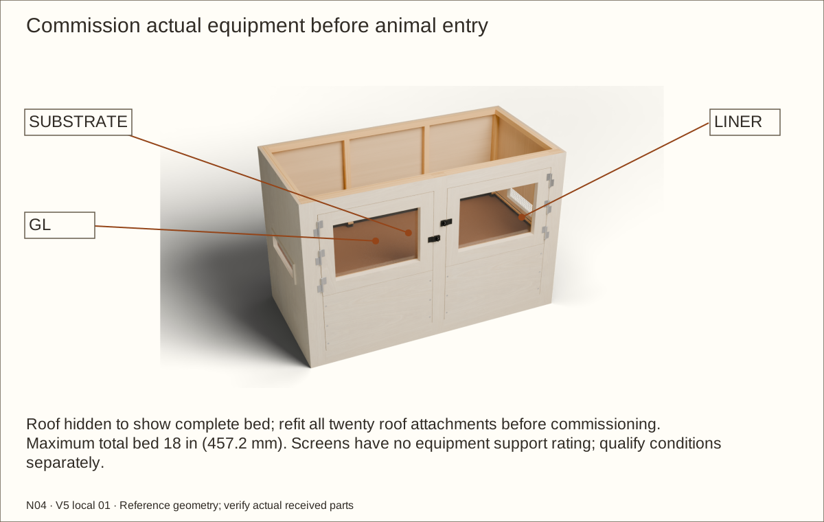
Commission before animal entry — 1
Choose the intended species, life stage and occupancy against current care requirements using the measured usable interior. This 72 in (1828.8 mm) × 36 in (914.4 mm) × 48 in (1219.2 mm) shell is a generic construction guide and assigns no species suitability.
Qualify every gap, latch and mesh opening for the occupant and feeders. Fit a mechanically retained finer barrier where needed, then reassess ventilation, visibility and cleaning.
Check before continuing: The intended species and life stage are recorded, with any finer containment barrier securely fitted.
Parts: Complete enclosure, support and received inventory, as described below
Tools / setup: Measuring tape, square, pencil and the tools named below
Before you begin: No animal suitability or equipment support rating is assigned by this construction guide.
Commission before animal entry — 2
Choose heat, light, ultraviolet and control equipment for the actual habitat. Follow each fixture’s mounting and combustible-clearance instructions, use independent supports and guards, and keep hot parts away from wood, acrylic, liner and animals. Do not place fixture weight on the mesh.
Plan any cable route against the real connector and strain relief before cutting. Put it above the liner, finish the cut wood and fit a retained closure. Never trap a cord in the roof joint or pierce the wet basin for a cable or improvised drain.
Check before continuing: Selected equipment has independent safe support and any cable routes are finished and secured before commissioning.
Parts: Complete enclosure, support and received inventory, as described below
Tools / setup: Measuring tape, square, pencil and the tools named below
Before you begin: No animal suitability or equipment support rating is assigned by this construction guide.
Commission before animal entry — 3
Run the complete configured habitat unoccupied through its intended day/night and wet/dry cycles. Record temperatures, humidity, ventilation, light exposure, thermostat control, safe surfaces, secure access and cleaning practicality before animal entry.
Check before continuing: Animal entry follows a separate documented species and equipment review, after construction is complete.
Choose ONE veneer species: 5 sheets of 48 × 96 in (1219.2 × 2438.4 mm). Trial stock is included. Resolve receiving holds before dependent work. Product identity checks do not guarantee destination stock or physical fit.
Exact allocation in current cutting layouts, including one trial board. Plane supported broad stock before ripping; glazing spacer rough 3/8 in (9.53 mm), fit to actual 0.351 in (8.92 mm) reference bare depth.
Seven full 1 1/2 in (38.1 mm) square × 96 in (2438.4 mm) boards; do not laminate these members.
Materials and hardware · continued
Choose ONE veneer species: 5 sheets of 48 × 96 in (1219.2 × 2438.4 mm). Trial stock is included. Resolve receiving holds before dependent work. Product identity checks do not guarantee destination stock or physical fit.
Three 19 in (482.6 mm) × 29 in (736.6 mm) roof blanks and two 19 in (482.6 mm) × 5 in (127 mm) side blanks; two-wire reference crossing 0.082 in (2.08 mm), not a 0.025 in (0.64 mm) slab. Occupant-specific containment review remains required.
Two 16-fluid-ounce (473 mL) bottles cover 38.6 sq ft (3.6 m²) of bond interfaces plus working reserve. The manufacturer excludes structural/load-bearing applications: use all scheduled mechanical stitches and do not infer a glue-only capacity.
Materials and hardware · continued
Choose ONE veneer species: 5 sheets of 48 × 96 in (1219.2 × 2438.4 mm). Trial stock is included. Resolve receiving holds before dependent work. Product identity checks do not guarantee destination stock or physical fit.
35057 Needed 118; 50 per package; buy 3 package(s)
Installed quantity is the exact source-station count; buy whole packs with spare screws.
Materials and hardware · continued
Choose ONE veneer species: 5 sheets of 48 × 96 in (1219.2 × 2438.4 mm). Trial stock is included. Resolve receiving holds before dependent work. Product identity checks do not guarantee destination stock or physical fit.
801782 Needed 36; 100 per package; buy 1 package(s)
Thirty-six installed, six per hinge; three LSX-100R on left and three LSX-100L on right. Confirm received hole/head seating and supplier approval before use; do not machine proprietary hinge holes from the model.
Materials and hardware · continued
Choose ONE veneer species: 5 sheets of 48 × 96 in (1219.2 × 2438.4 mm). Trial stock is included. Resolve receiving holds before dependent work. Product identity checks do not guarantee destination stock or physical fit.
LSX-100R Needed 3; 1 per package; buy 3 package(s)
Three on the guide’s left jamb: the manufacturer’s shown fixed pin half lies left of the axis and points upward. Sold individually, without screws. Confirm hand against the received parts, not the door name alone.
LSX-100L Needed 3; 1 per package; buy 3 package(s)
Three mirrored hinges on the right jamb. Stainless steel; fixed upward pin and removable upper socket. The 66 lb (30 kg) published pair capacity does not rate this wood assembly or establish a multiplied three-hinge capacity.
Materials and hardware · continued
Choose ONE veneer species: 5 sheets of 48 × 96 in (1219.2 × 2438.4 mm). Trial stock is included. Resolve receiving holds before dependent work. Product identity checks do not guarantee destination stock or physical fit.
N305-979 Needed 2; 1 per package; buy 2 package(s)
One independent closure per door. Turn the swivel across the slot to secure; align it with the slot to lift the flap. Optional padlocks are not included or required for the illustrated keyless operation.
21232102 Needed 1; 1 per package; buy 1 package(s)
One sheet supplies both 23 51/64 in (604.44 mm) × 16 23/32 in (424.66 mm) panes. Confirm full received width before cutting. Thickness is exactly 0.22 in (5.59 mm), not a nominal 1/4 in (6.35 mm) substituted without adjusting the pocket.
One 124 in (3149.6 mm) × 88 in (2235.2 mm) uncut blank from 10 × 12-foot stock; actual uncut fold trial and material suitability required.
Materials and hardware · continued
Choose ONE veneer species: 5 sheets of 48 × 96 in (1219.2 × 2438.4 mm). Trial stock is included. Resolve receiving holds before dependent work. Product identity checks do not guarantee destination stock or physical fit.
One 124 in (3149.6 mm) × 88 in (2235.2 mm) blank from 10 × 12-foot stock; reference compressed 0.08 in (2.03 mm) is not a measured material gauge. Add loose protection over recessed hardware.
One inside each recessed post under locknut. 5/8 in (15.88 mm) outside and 9/32 in (7.14 mm) inside diameters; receive thickness at most 1/16 in (1.59 mm) for this reference stack.
Materials and hardware · continued
Choose ONE veneer species: 5 sheets of 48 × 96 in (1219.2 × 2438.4 mm). Trial stock is included. Resolve receiving holds before dependent work. Product identity checks do not guarantee destination stock or physical fit.
One inside each recessed post. Listed height 0.298 in (7.57 mm)–0.328 in (8.33 mm); two full threads beyond nylon, entire tail below post face. Hand-tighten to avoid stainless galling; never force seized threads.
4 × 8 ft selected species / 3M PSA; configuration to confirm Needed 5; 1 per package; buy 5 package(s) Choose one species
Full exterior, edges/reveals and trial; supplier balance/backer/adhesive and cured-finish acceptance required
Materials and hardware · continued
Choose ONE veneer species: 5 sheets of 48 × 96 in (1219.2 × 2438.4 mm). Trial stock is included. Resolve receiving holds before dependent work. Product identity checks do not guarantee destination stock or physical fit.
4 × 8 ft selected species / 3M PSA; configuration to confirm Needed 5; 1 per package; buy 5 package(s) Choose one species
Full exterior, edges/reveals and trial; supplier balance/backer/adhesive and cured-finish acceptance required
Cut list
Cut list
One of each named ID. Decimal inches are rounded to four places; exact values remain in the specification. Rough blanks include scheduled trimming. Thickness below is the prepared blank, not the purchased board: plane the 3/4-inch (19.05 mm) pine safely to 3/8 inch (9.53 mm) before ripping thin captures and lining clamps. Glazing spacers begin at the listed 3/8-inch (9.53 mm) thickness and are fitted separately. Reference finished sizes need actual-material fitting. V-parts represent the complete cured veneer stack. Cut each of the two acrylic panes only after its cured pocket, actual thickness and movement clearance are measured. SETL/SETR layer IDs are individual dry layers; two form each lower setting support.
Part
Rough length × width × prepared thickness
Reference finished size
P01 · Floor
72 1/8 in (1831.98 mm) × 36 1/16 in (915.99 mm) × 45/64 in (17.86 mm)
72 in (1828.8 mm) × 36 in (914.4 mm) × 45/64 in (17.86 mm)
P02 · Removable roof
72 1/8 in (1831.98 mm) × 36 1/16 in (915.99 mm) × 45/64 in (17.86 mm)
72 in (1828.8 mm) × 36 in (914.4 mm) × 45/64 in (17.86 mm)
P03L · L wall
46 23/32 in (1186.66 mm) × 36 1/16 in (915.99 mm) × 45/64 in (17.86 mm)
46 19/32 in (1183.48 mm) × 36 in (914.4 mm) × 45/64 in (17.86 mm)
P03R · R wall
46 23/32 in (1186.66 mm) × 36 1/16 in (915.99 mm) × 45/64 in (17.86 mm)
46 19/32 in (1183.48 mm) × 36 in (914.4 mm) × 45/64 in (17.86 mm)
P04 · Back
70 23/32 in (1796.26 mm) × 46 21/32 in (1185.07 mm) × 45/64 in (17.86 mm)
70 19/32 in (1793.08 mm) × 46 19/32 in (1183.48 mm) × 45/64 in (17.86 mm)
CLB · L bottom cleat
32 27/64 in (823.52 mm) × 1 1/2 in (38.1 mm) × 1 1/2 in (38.1 mm)
32 19/64 in (820.34 mm) × 1 1/2 in (38.1 mm) × 1 1/2 in (38.1 mm)
CLU · L rear upright
43 23/32 in (1110.46 mm) × 1 1/2 in (38.1 mm) × 1 1/2 in (38.1 mm)
43 19/32 in (1107.28 mm) × 1 1/2 in (38.1 mm) × 1 1/2 in (38.1 mm)
CLT · L upper cleat
32 27/64 in (823.52 mm) × 1 1/2 in (38.1 mm) × 1 1/2 in (38.1 mm)
32 19/64 in (820.34 mm) × 1 1/2 in (38.1 mm) × 1 1/2 in (38.1 mm)
CRB · R bottom cleat
32 27/64 in (823.52 mm) × 1 1/2 in (38.1 mm) × 1 1/2 in (38.1 mm)
32 19/64 in (820.34 mm) × 1 1/2 in (38.1 mm) × 1 1/2 in (38.1 mm)
CRU · R rear upright
43 23/32 in (1110.46 mm) × 1 1/2 in (38.1 mm) × 1 1/2 in (38.1 mm)
43 19/32 in (1107.28 mm) × 1 1/2 in (38.1 mm) × 1 1/2 in (38.1 mm)
Cut list · continued
One of each named ID. Decimal inches are rounded to four places; exact values remain in the specification. Rough blanks include scheduled trimming. Thickness below is the prepared blank, not the purchased board: plane the 3/4-inch (19.05 mm) pine safely to 3/8 inch (9.53 mm) before ripping thin captures and lining clamps. Glazing spacers begin at the listed 3/8-inch (9.53 mm) thickness and are fitted separately. Reference finished sizes need actual-material fitting. V-parts represent the complete cured veneer stack. Cut each of the two acrylic panes only after its cured pocket, actual thickness and movement clearance are measured. SETL/SETR layer IDs are individual dry layers; two form each lower setting support.
Part
Rough length × width × prepared thickness
Reference finished size
CRT · R upper cleat
32 27/64 in (823.52 mm) × 1 1/2 in (38.1 mm) × 1 1/2 in (38.1 mm)
32 19/64 in (820.34 mm) × 1 1/2 in (38.1 mm) × 1 1/2 in (38.1 mm)
CB · Back floor cleat
67 23/32 in (1720.06 mm) × 1 1/2 in (38.1 mm) × 1 1/2 in (38.1 mm)
67 19/32 in (1716.88 mm) × 1 1/2 in (38.1 mm) × 1 1/2 in (38.1 mm)
CT · Back upper cleat
67 23/32 in (1720.06 mm) × 1 1/2 in (38.1 mm) × 1 1/2 in (38.1 mm)
67 19/32 in (1716.88 mm) × 1 1/2 in (38.1 mm) × 1 1/2 in (38.1 mm)
CM1 · Intermediate rear upright
43 23/32 in (1110.46 mm) × 1 1/2 in (38.1 mm) × 1 1/2 in (38.1 mm)
43 19/32 in (1107.28 mm) × 1 1/2 in (38.1 mm) × 1 1/2 in (38.1 mm)
CM2 · Intermediate rear upright
43 23/32 in (1110.46 mm) × 1 1/2 in (38.1 mm) × 1 1/2 in (38.1 mm)
43 19/32 in (1107.28 mm) × 1 1/2 in (38.1 mm) × 1 1/2 in (38.1 mm)
CR1 · Roof web rib
30 59/64 in (785.42 mm) × 1 1/2 in (38.1 mm) × 1 1/2 in (38.1 mm)
30 51/64 in (782.24 mm) × 1 1/2 in (38.1 mm) × 1 1/2 in (38.1 mm)
CR2 · Roof web rib
30 59/64 in (785.42 mm) × 1 1/2 in (38.1 mm) × 1 1/2 in (38.1 mm)
30 51/64 in (782.24 mm) × 1 1/2 in (38.1 mm) × 1 1/2 in (38.1 mm)
F0L · L full front-frame upright layer
46 23/32 in (1186.66 mm) × 3 9/16 in (90.49 mm) × 3/4 in (19.05 mm)
46 19/32 in (1183.48 mm) × 3 1/2 in (88.9 mm) × 3/4 in (19.05 mm)
F0M · M full front-frame upright layer
46 23/32 in (1186.66 mm) × 3 9/16 in (90.49 mm) × 3/4 in (19.05 mm)
46 19/32 in (1183.48 mm) × 3 1/2 in (88.9 mm) × 3/4 in (19.05 mm)
F0R · R full front-frame upright layer
46 23/32 in (1186.66 mm) × 3 9/16 in (90.49 mm) × 3/4 in (19.05 mm)
46 19/32 in (1183.48 mm) × 3 1/2 in (88.9 mm) × 3/4 in (19.05 mm)
Cut list · continued
One of each named ID. Decimal inches are rounded to four places; exact values remain in the specification. Rough blanks include scheduled trimming. Thickness below is the prepared blank, not the purchased board: plane the 3/4-inch (19.05 mm) pine safely to 3/8 inch (9.53 mm) before ripping thin captures and lining clamps. Glazing spacers begin at the listed 3/8-inch (9.53 mm) thickness and are fitted separately. Reference finished sizes need actual-material fitting. V-parts represent the complete cured veneer stack. Cut each of the two acrylic panes only after its cured pocket, actual thickness and movement clearance are measured. SETL/SETR layer IDs are individual dry layers; two form each lower setting support.
Part
Rough length × width × prepared thickness
Reference finished size
F0BL · Front-frame rail between uprights
30 11/64 in (766.37 mm) × 3 9/16 in (90.49 mm) × 3/4 in (19.05 mm)
30 3/64 in (763.19 mm) × 3 1/2 in (88.9 mm) × 3/4 in (19.05 mm)
F0BR · Front-frame rail between uprights
30 11/64 in (766.37 mm) × 3 9/16 in (90.49 mm) × 3/4 in (19.05 mm)
30 3/64 in (763.19 mm) × 3 1/2 in (88.9 mm) × 3/4 in (19.05 mm)
F0TL · Front-frame rail between uprights
30 11/64 in (766.37 mm) × 3 9/16 in (90.49 mm) × 3/4 in (19.05 mm)
30 3/64 in (763.19 mm) × 3 1/2 in (88.9 mm) × 3/4 in (19.05 mm)
F0TR · Front-frame rail between uprights
30 11/64 in (766.37 mm) × 3 9/16 in (90.49 mm) × 3/4 in (19.05 mm)
30 3/64 in (763.19 mm) × 3 1/2 in (88.9 mm) × 3/4 in (19.05 mm)
F1L · L full front-frame upright layer
39 23/32 in (1008.86 mm) × 3 9/16 in (90.49 mm) × 3/4 in (19.05 mm)
39 19/32 in (1005.68 mm) × 3 1/2 in (88.9 mm) × 3/4 in (19.05 mm)
F1M · M full front-frame upright layer
39 23/32 in (1008.86 mm) × 3 9/16 in (90.49 mm) × 3/4 in (19.05 mm)
39 19/32 in (1005.68 mm) × 3 1/2 in (88.9 mm) × 3/4 in (19.05 mm)
F1R · R full front-frame upright layer
39 23/32 in (1008.86 mm) × 3 9/16 in (90.49 mm) × 3/4 in (19.05 mm)
39 19/32 in (1005.68 mm) × 3 1/2 in (88.9 mm) × 3/4 in (19.05 mm)
F1B · Continuous front-frame rail layer
70 23/32 in (1796.26 mm) × 3 9/16 in (90.49 mm) × 3/4 in (19.05 mm)
70 19/32 in (1793.08 mm) × 3 1/2 in (88.9 mm) × 3/4 in (19.05 mm)
F1T · Continuous front-frame rail layer
70 23/32 in (1796.26 mm) × 3 9/16 in (90.49 mm) × 3/4 in (19.05 mm)
70 19/32 in (1793.08 mm) × 3 1/2 in (88.9 mm) × 3/4 in (19.05 mm)
F2L · L full front-frame upright layer
46 23/32 in (1186.66 mm) × 3 9/16 in (90.49 mm) × 3/4 in (19.05 mm)
46 19/32 in (1183.48 mm) × 3 1/2 in (88.9 mm) × 3/4 in (19.05 mm)
Cut list · continued
One of each named ID. Decimal inches are rounded to four places; exact values remain in the specification. Rough blanks include scheduled trimming. Thickness below is the prepared blank, not the purchased board: plane the 3/4-inch (19.05 mm) pine safely to 3/8 inch (9.53 mm) before ripping thin captures and lining clamps. Glazing spacers begin at the listed 3/8-inch (9.53 mm) thickness and are fitted separately. Reference finished sizes need actual-material fitting. V-parts represent the complete cured veneer stack. Cut each of the two acrylic panes only after its cured pocket, actual thickness and movement clearance are measured. SETL/SETR layer IDs are individual dry layers; two form each lower setting support.
Part
Rough length × width × prepared thickness
Reference finished size
F2M · M full front-frame upright layer
46 23/32 in (1186.66 mm) × 3 9/16 in (90.49 mm) × 3/4 in (19.05 mm)
46 19/32 in (1183.48 mm) × 3 1/2 in (88.9 mm) × 3/4 in (19.05 mm)
F2R · R full front-frame upright layer
46 23/32 in (1186.66 mm) × 3 9/16 in (90.49 mm) × 3/4 in (19.05 mm)
46 19/32 in (1183.48 mm) × 3 1/2 in (88.9 mm) × 3/4 in (19.05 mm)
F2BL · Front-frame rail between uprights
30 11/64 in (766.37 mm) × 3 9/16 in (90.49 mm) × 3/4 in (19.05 mm)
30 3/64 in (763.19 mm) × 3 1/2 in (88.9 mm) × 3/4 in (19.05 mm)
F2BR · Front-frame rail between uprights
30 11/64 in (766.37 mm) × 3 9/16 in (90.49 mm) × 3/4 in (19.05 mm)
30 3/64 in (763.19 mm) × 3 1/2 in (88.9 mm) × 3/4 in (19.05 mm)
F2TL · Front-frame rail between uprights
30 11/64 in (766.37 mm) × 3 9/16 in (90.49 mm) × 3/4 in (19.05 mm)
30 3/64 in (763.19 mm) × 3 1/2 in (88.9 mm) × 3/4 in (19.05 mm)
F2TR · Front-frame rail between uprights
30 11/64 in (766.37 mm) × 3 9/16 in (90.49 mm) × 3/4 in (19.05 mm)
30 3/64 in (763.19 mm) × 3 1/2 in (88.9 mm) × 3/4 in (19.05 mm)
F3L · L full front-frame upright layer
39 23/32 in (1008.86 mm) × 3 9/16 in (90.49 mm) × 3/4 in (19.05 mm)
39 19/32 in (1005.68 mm) × 3 1/2 in (88.9 mm) × 3/4 in (19.05 mm)
F3M · M full front-frame upright layer
39 23/32 in (1008.86 mm) × 3 9/16 in (90.49 mm) × 3/4 in (19.05 mm)
39 19/32 in (1005.68 mm) × 3 1/2 in (88.9 mm) × 3/4 in (19.05 mm)
F3R · R full front-frame upright layer
39 23/32 in (1008.86 mm) × 3 9/16 in (90.49 mm) × 3/4 in (19.05 mm)
39 19/32 in (1005.68 mm) × 3 1/2 in (88.9 mm) × 3/4 in (19.05 mm)
F3B · Continuous front-frame rail layer
70 23/32 in (1796.26 mm) × 3 9/16 in (90.49 mm) × 3/4 in (19.05 mm)
70 19/32 in (1793.08 mm) × 3 1/2 in (88.9 mm) × 3/4 in (19.05 mm)
Cut list · continued
One of each named ID. Decimal inches are rounded to four places; exact values remain in the specification. Rough blanks include scheduled trimming. Thickness below is the prepared blank, not the purchased board: plane the 3/4-inch (19.05 mm) pine safely to 3/8 inch (9.53 mm) before ripping thin captures and lining clamps. Glazing spacers begin at the listed 3/8-inch (9.53 mm) thickness and are fitted separately. Reference finished sizes need actual-material fitting. V-parts represent the complete cured veneer stack. Cut each of the two acrylic panes only after its cured pocket, actual thickness and movement clearance are measured. SETL/SETR layer IDs are individual dry layers; two form each lower setting support.
Part
Rough length × width × prepared thickness
Reference finished size
F3T · Continuous front-frame rail layer
70 23/32 in (1796.26 mm) × 3 9/16 in (90.49 mm) × 3/4 in (19.05 mm)
70 19/32 in (1793.08 mm) × 3 1/2 in (88.9 mm) × 3/4 in (19.05 mm)
RBL1 · Removable retainer lamination
29 55/64 in (758.43 mm) × 16 11/16 in (423.86 mm) × 45/64 in (17.86 mm)
29 47/64 in (755.25 mm) × 16 5/8 in (422.28 mm) × 45/64 in (17.86 mm)
RBL2 · Removable retainer lamination
29 55/64 in (758.43 mm) × 16 11/16 in (423.86 mm) × 45/64 in (17.86 mm)
29 47/64 in (755.25 mm) × 16 5/8 in (422.28 mm) × 45/64 in (17.86 mm)
RBL3 · Removable retainer lamination
29 55/64 in (758.43 mm) × 16 11/16 in (423.86 mm) × 45/64 in (17.86 mm)
29 47/64 in (755.25 mm) × 16 5/8 in (422.28 mm) × 45/64 in (17.86 mm)
RCLL · Retainer bolt receiver
16 3/4 in (425.45 mm) × 1 1/2 in (38.1 mm) × 1 1/2 in (38.1 mm)
16 5/8 in (422.28 mm) × 1 1/2 in (38.1 mm) × 1 1/2 in (38.1 mm)
RCLR · Retainer bolt receiver
16 3/4 in (425.45 mm) × 1 1/2 in (38.1 mm) × 1 1/2 in (38.1 mm)
16 5/8 in (422.28 mm) × 1 1/2 in (38.1 mm) × 1 1/2 in (38.1 mm)
RBR1 · Removable retainer lamination
29 55/64 in (758.43 mm) × 16 11/16 in (423.86 mm) × 45/64 in (17.86 mm)
29 47/64 in (755.25 mm) × 16 5/8 in (422.28 mm) × 45/64 in (17.86 mm)
RBR2 · Removable retainer lamination
29 55/64 in (758.43 mm) × 16 11/16 in (423.86 mm) × 45/64 in (17.86 mm)
29 47/64 in (755.25 mm) × 16 5/8 in (422.28 mm) × 45/64 in (17.86 mm)
RBR3 · Removable retainer lamination
29 55/64 in (758.43 mm) × 16 11/16 in (423.86 mm) × 45/64 in (17.86 mm)
29 47/64 in (755.25 mm) × 16 5/8 in (422.28 mm) × 45/64 in (17.86 mm)
RCRL · Retainer bolt receiver
16 3/4 in (425.45 mm) × 1 1/2 in (38.1 mm) × 1 1/2 in (38.1 mm)
16 5/8 in (422.28 mm) × 1 1/2 in (38.1 mm) × 1 1/2 in (38.1 mm)
Cut list · continued
One of each named ID. Decimal inches are rounded to four places; exact values remain in the specification. Rough blanks include scheduled trimming. Thickness below is the prepared blank, not the purchased board: plane the 3/4-inch (19.05 mm) pine safely to 3/8 inch (9.53 mm) before ripping thin captures and lining clamps. Glazing spacers begin at the listed 3/8-inch (9.53 mm) thickness and are fitted separately. Reference finished sizes need actual-material fitting. V-parts represent the complete cured veneer stack. Cut each of the two acrylic panes only after its cured pocket, actual thickness and movement clearance are measured. SETL/SETR layer IDs are individual dry layers; two form each lower setting support.
Part
Rough length × width × prepared thickness
Reference finished size
RCRR · Retainer bolt receiver
16 3/4 in (425.45 mm) × 1 1/2 in (38.1 mm) × 1 1/2 in (38.1 mm)
16 5/8 in (422.28 mm) × 1 1/2 in (38.1 mm) × 1 1/2 in (38.1 mm)
ML · L vent mesh
19 in (482.6 mm) × 5 in (127 mm) × 0.082 in (2.08 mm)
19 in (482.6 mm) × 5 in (127 mm) × 0.082 in (2.08 mm)
VLB · Vent capture strip
20 1/8 in (511.18 mm) × 1 1/16 in (26.99 mm) × 3/8 in (9.53 mm)
20 in (508 mm) × 1 in (25.4 mm) × 3/8 in (9.53 mm)
VLT · Vent capture strip
20 1/8 in (511.18 mm) × 1 1/16 in (26.99 mm) × 3/8 in (9.53 mm)
20 in (508 mm) × 1 in (25.4 mm) × 3/8 in (9.53 mm)
VLF · Vent end strip
4 1/8 in (104.78 mm) × 1 1/16 in (26.99 mm) × 3/8 in (9.53 mm)
4 in (101.6 mm) × 1 in (25.4 mm) × 3/8 in (9.53 mm)
VLA · Vent end strip
4 1/8 in (104.78 mm) × 1 1/16 in (26.99 mm) × 3/8 in (9.53 mm)
4 in (101.6 mm) × 1 in (25.4 mm) × 3/8 in (9.53 mm)
MR · R vent mesh
19 in (482.6 mm) × 5 in (127 mm) × 0.082 in (2.08 mm)
19 in (482.6 mm) × 5 in (127 mm) × 0.082 in (2.08 mm)
VRB · Vent capture strip
20 1/8 in (511.18 mm) × 1 1/16 in (26.99 mm) × 3/8 in (9.53 mm)
20 in (508 mm) × 1 in (25.4 mm) × 3/8 in (9.53 mm)
VRT · Vent capture strip
20 1/8 in (511.18 mm) × 1 1/16 in (26.99 mm) × 3/8 in (9.53 mm)
20 in (508 mm) × 1 in (25.4 mm) × 3/8 in (9.53 mm)
VRF · Vent end strip
4 1/8 in (104.78 mm) × 1 1/16 in (26.99 mm) × 3/8 in (9.53 mm)
4 in (101.6 mm) × 1 in (25.4 mm) × 3/8 in (9.53 mm)
Cut list · continued
One of each named ID. Decimal inches are rounded to four places; exact values remain in the specification. Rough blanks include scheduled trimming. Thickness below is the prepared blank, not the purchased board: plane the 3/4-inch (19.05 mm) pine safely to 3/8 inch (9.53 mm) before ripping thin captures and lining clamps. Glazing spacers begin at the listed 3/8-inch (9.53 mm) thickness and are fitted separately. Reference finished sizes need actual-material fitting. V-parts represent the complete cured veneer stack. Cut each of the two acrylic panes only after its cured pocket, actual thickness and movement clearance are measured. SETL/SETR layer IDs are individual dry layers; two form each lower setting support.
Part
Rough length × width × prepared thickness
Reference finished size
VRA · Vent end strip
4 1/8 in (104.78 mm) × 1 1/16 in (26.99 mm) × 3/8 in (9.53 mm)
4 in (101.6 mm) × 1 in (25.4 mm) × 3/8 in (9.53 mm)
MTL · Roof mesh
29 in (736.6 mm) × 19 in (482.6 mm) × 0.082 in (2.08 mm)
29 in (736.6 mm) × 19 in (482.6 mm) × 0.082 in (2.08 mm)
RTLF · Roof capture strip
20 1/8 in (511.18 mm) × 1 1/16 in (26.99 mm) × 3/8 in (9.53 mm)
20 in (508 mm) × 1 in (25.4 mm) × 3/8 in (9.53 mm)
RTLA · Roof capture strip
20 1/8 in (511.18 mm) × 1 1/16 in (26.99 mm) × 3/8 in (9.53 mm)
20 in (508 mm) × 1 in (25.4 mm) × 3/8 in (9.53 mm)
RTLL · Roof end capture
28 1/8 in (714.38 mm) × 1 1/16 in (26.99 mm) × 3/8 in (9.53 mm)
28 in (711.2 mm) × 1 in (25.4 mm) × 3/8 in (9.53 mm)
RTLR · Roof end capture
28 1/8 in (714.38 mm) × 1 1/16 in (26.99 mm) × 3/8 in (9.53 mm)
28 in (711.2 mm) × 1 in (25.4 mm) × 3/8 in (9.53 mm)
MTM · Roof mesh
29 in (736.6 mm) × 19 in (482.6 mm) × 0.082 in (2.08 mm)
29 in (736.6 mm) × 19 in (482.6 mm) × 0.082 in (2.08 mm)
RTMF · Roof capture strip
20 1/8 in (511.18 mm) × 1 1/16 in (26.99 mm) × 3/8 in (9.53 mm)
20 in (508 mm) × 1 in (25.4 mm) × 3/8 in (9.53 mm)
RTMA · Roof capture strip
20 1/8 in (511.18 mm) × 1 1/16 in (26.99 mm) × 3/8 in (9.53 mm)
20 in (508 mm) × 1 in (25.4 mm) × 3/8 in (9.53 mm)
RTML · Roof end capture
28 1/8 in (714.38 mm) × 1 1/16 in (26.99 mm) × 3/8 in (9.53 mm)
28 in (711.2 mm) × 1 in (25.4 mm) × 3/8 in (9.53 mm)
Cut list · continued
One of each named ID. Decimal inches are rounded to four places; exact values remain in the specification. Rough blanks include scheduled trimming. Thickness below is the prepared blank, not the purchased board: plane the 3/4-inch (19.05 mm) pine safely to 3/8 inch (9.53 mm) before ripping thin captures and lining clamps. Glazing spacers begin at the listed 3/8-inch (9.53 mm) thickness and are fitted separately. Reference finished sizes need actual-material fitting. V-parts represent the complete cured veneer stack. Cut each of the two acrylic panes only after its cured pocket, actual thickness and movement clearance are measured. SETL/SETR layer IDs are individual dry layers; two form each lower setting support.
Part
Rough length × width × prepared thickness
Reference finished size
RTMR · Roof end capture
28 1/8 in (714.38 mm) × 1 1/16 in (26.99 mm) × 3/8 in (9.53 mm)
28 in (711.2 mm) × 1 in (25.4 mm) × 3/8 in (9.53 mm)
MTR · Roof mesh
29 in (736.6 mm) × 19 in (482.6 mm) × 0.082 in (2.08 mm)
29 in (736.6 mm) × 19 in (482.6 mm) × 0.082 in (2.08 mm)
RTRF · Roof capture strip
20 1/8 in (511.18 mm) × 1 1/16 in (26.99 mm) × 3/8 in (9.53 mm)
20 in (508 mm) × 1 in (25.4 mm) × 3/8 in (9.53 mm)
RTRA · Roof capture strip
20 1/8 in (511.18 mm) × 1 1/16 in (26.99 mm) × 3/8 in (9.53 mm)
20 in (508 mm) × 1 in (25.4 mm) × 3/8 in (9.53 mm)
RTRL · Roof end capture
28 1/8 in (714.38 mm) × 1 1/16 in (26.99 mm) × 3/8 in (9.53 mm)
28 in (711.2 mm) × 1 in (25.4 mm) × 3/8 in (9.53 mm)
RTRR · Roof end capture
28 1/8 in (714.38 mm) × 1 1/16 in (26.99 mm) × 3/8 in (9.53 mm)
28 in (711.2 mm) × 1 in (25.4 mm) × 3/8 in (9.53 mm)
DL0L · Door stile layer
22 23/32 in (577.06 mm) × 3 1/2 in (88.9 mm) × 3/4 in (19.05 mm)
22 19/32 in (573.88 mm) × 3 7/16 in (87.31 mm) × 3/4 in (19.05 mm)
DL0R · Door stile layer
22 23/32 in (577.06 mm) × 3 17/32 in (89.69 mm) × 3/4 in (19.05 mm)
22 19/32 in (573.88 mm) × 3 15/32 in (88.11 mm) × 3/4 in (19.05 mm)
DL0B · Door rail layer
22 59/64 in (582.22 mm) × 3 1/2 in (88.9 mm) × 3/4 in (19.05 mm)
22 51/64 in (579.04 mm) × 3 7/16 in (87.31 mm) × 3/4 in (19.05 mm)
DL0T · Door rail layer
22 59/64 in (582.22 mm) × 3 1/2 in (88.9 mm) × 3/4 in (19.05 mm)
22 51/64 in (579.04 mm) × 3 7/16 in (87.31 mm) × 3/4 in (19.05 mm)
Cut list · continued
One of each named ID. Decimal inches are rounded to four places; exact values remain in the specification. Rough blanks include scheduled trimming. Thickness below is the prepared blank, not the purchased board: plane the 3/4-inch (19.05 mm) pine safely to 3/8 inch (9.53 mm) before ripping thin captures and lining clamps. Glazing spacers begin at the listed 3/8-inch (9.53 mm) thickness and are fitted separately. Reference finished sizes need actual-material fitting. V-parts represent the complete cured veneer stack. Cut each of the two acrylic panes only after its cured pocket, actual thickness and movement clearance are measured. SETL/SETR layer IDs are individual dry layers; two form each lower setting support.
Part
Rough length × width × prepared thickness
Reference finished size
DL1L · Door stile layer
15 27/32 in (402.43 mm) × 3 1/2 in (88.9 mm) × 3/4 in (19.05 mm)
15 23/32 in (399.26 mm) × 3 7/16 in (87.31 mm) × 3/4 in (19.05 mm)
DL1R · Door stile layer
15 27/32 in (402.43 mm) × 3 17/32 in (89.69 mm) × 3/4 in (19.05 mm)
15 23/32 in (399.26 mm) × 3 15/32 in (88.11 mm) × 3/4 in (19.05 mm)
DL1B · Door rail layer
29 53/64 in (757.63 mm) × 3 1/2 in (88.9 mm) × 3/4 in (19.05 mm)
29 45/64 in (754.46 mm) × 3 7/16 in (87.31 mm) × 3/4 in (19.05 mm)
DL1T · Door rail layer
29 53/64 in (757.63 mm) × 3 1/2 in (88.9 mm) × 3/4 in (19.05 mm)
29 45/64 in (754.46 mm) × 3 7/16 in (87.31 mm) × 3/4 in (19.05 mm)
GL · Unpierced OPTIX acrylic pane
23 55/64 in (606.03 mm) × 16 25/32 in (426.24 mm) × 0.22 in (5.59 mm)
23 51/64 in (604.44 mm) × 16 23/32 in (424.66 mm) × 0.22 in (5.59 mm)
SPLL · Glazing side spacer
18 19/32 in (472.28 mm) × 13/16 in (20.64 mm) × 3/8 in (9.53 mm)
18 15/32 in (469.11 mm) × 3/4 in (19.05 mm) × 0.351 in (8.92 mm)
SPLR · Glazing side spacer
18 19/32 in (472.28 mm) × 13/16 in (20.64 mm) × 3/8 in (9.53 mm)
18 15/32 in (469.11 mm) × 3/4 in (19.05 mm) × 0.351 in (8.92 mm)
SPLB · Glazing end spacer
24 11/64 in (613.97 mm) × 13/16 in (20.64 mm) × 3/8 in (9.53 mm)
24 3/64 in (610.79 mm) × 3/4 in (19.05 mm) × 0.351 in (8.92 mm)
SPLT · Glazing end spacer
24 11/64 in (613.97 mm) × 13/16 in (20.64 mm) × 3/8 in (9.53 mm)
24 3/64 in (610.79 mm) × 3/4 in (19.05 mm) × 0.351 in (8.92 mm)
BELL · Removable glazing side bead
18 19/32 in (472.28 mm) × 1 5/16 in (33.34 mm) × 1/4 in (6.35 mm)
18 15/32 in (469.11 mm) × 1 1/4 in (31.75 mm) × 1/4 in (6.35 mm)
Cut list · continued
One of each named ID. Decimal inches are rounded to four places; exact values remain in the specification. Rough blanks include scheduled trimming. Thickness below is the prepared blank, not the purchased board: plane the 3/4-inch (19.05 mm) pine safely to 3/8 inch (9.53 mm) before ripping thin captures and lining clamps. Glazing spacers begin at the listed 3/8-inch (9.53 mm) thickness and are fitted separately. Reference finished sizes need actual-material fitting. V-parts represent the complete cured veneer stack. Cut each of the two acrylic panes only after its cured pocket, actual thickness and movement clearance are measured. SETL/SETR layer IDs are individual dry layers; two form each lower setting support.
Part
Rough length × width × prepared thickness
Reference finished size
BELR · Removable glazing side bead
18 19/32 in (472.28 mm) × 1 5/16 in (33.34 mm) × 1/4 in (6.35 mm)
18 15/32 in (469.11 mm) × 1 1/4 in (31.75 mm) × 1/4 in (6.35 mm)
BELB · Removable glazing end bead
23 11/64 in (588.57 mm) × 1 5/16 in (33.34 mm) × 1/4 in (6.35 mm)
23 3/64 in (585.39 mm) × 1 1/4 in (31.75 mm) × 1/4 in (6.35 mm)
BELT · Removable glazing end bead
23 11/64 in (588.57 mm) × 1 5/16 in (33.34 mm) × 1/4 in (6.35 mm)
23 3/64 in (585.39 mm) × 1 1/4 in (31.75 mm) × 1/4 in (6.35 mm)
PADLLF · Dry glazing face pad
16 23/32 in (424.66 mm) × 3/8 in (9.53 mm) × 1/16 in (1.59 mm)
16 23/32 in (424.66 mm) × 3/8 in (9.53 mm) × 1/16 in (1.59 mm)
PADLLB · Dry glazing face pad
16 23/32 in (424.66 mm) × 3/8 in (9.53 mm) × 1/16 in (1.59 mm)
16 23/32 in (424.66 mm) × 3/8 in (9.53 mm) × 1/16 in (1.59 mm)
PADLRF · Dry glazing face pad
16 23/32 in (424.66 mm) × 3/8 in (9.53 mm) × 1/16 in (1.59 mm)
16 23/32 in (424.66 mm) × 3/8 in (9.53 mm) × 1/16 in (1.59 mm)
PADLRB · Dry glazing face pad
16 23/32 in (424.66 mm) × 3/8 in (9.53 mm) × 1/16 in (1.59 mm)
16 23/32 in (424.66 mm) × 3/8 in (9.53 mm) × 1/16 in (1.59 mm)
PADLBF · Dry glazing end pad
23 3/64 in (585.39 mm) × 3/8 in (9.53 mm) × 1/16 in (1.59 mm)
23 3/64 in (585.39 mm) × 3/8 in (9.53 mm) × 1/16 in (1.59 mm)
PADLBB · Dry glazing end pad
23 3/64 in (585.39 mm) × 3/8 in (9.53 mm) × 1/16 in (1.59 mm)
23 3/64 in (585.39 mm) × 3/8 in (9.53 mm) × 1/16 in (1.59 mm)
PADLTF · Dry glazing end pad
23 3/64 in (585.39 mm) × 3/8 in (9.53 mm) × 1/16 in (1.59 mm)
23 3/64 in (585.39 mm) × 3/8 in (9.53 mm) × 1/16 in (1.59 mm)
Cut list · continued
One of each named ID. Decimal inches are rounded to four places; exact values remain in the specification. Rough blanks include scheduled trimming. Thickness below is the prepared blank, not the purchased board: plane the 3/4-inch (19.05 mm) pine safely to 3/8 inch (9.53 mm) before ripping thin captures and lining clamps. Glazing spacers begin at the listed 3/8-inch (9.53 mm) thickness and are fitted separately. Reference finished sizes need actual-material fitting. V-parts represent the complete cured veneer stack. Cut each of the two acrylic panes only after its cured pocket, actual thickness and movement clearance are measured. SETL/SETR layer IDs are individual dry layers; two form each lower setting support.
Part
Rough length × width × prepared thickness
Reference finished size
PADLTB · Dry glazing end pad
23 3/64 in (585.39 mm) × 3/8 in (9.53 mm) × 1/16 in (1.59 mm)
23 3/64 in (585.39 mm) × 3/8 in (9.53 mm) × 1/16 in (1.59 mm)
DR0L · Door stile layer
22 23/32 in (577.06 mm) × 3 17/32 in (89.69 mm) × 3/4 in (19.05 mm)
22 19/32 in (573.88 mm) × 3 15/32 in (88.11 mm) × 3/4 in (19.05 mm)
DR0R · Door stile layer
22 23/32 in (577.06 mm) × 3 1/2 in (88.9 mm) × 3/4 in (19.05 mm)
22 19/32 in (573.88 mm) × 3 7/16 in (87.31 mm) × 3/4 in (19.05 mm)
DR0B · Door rail layer
22 59/64 in (582.22 mm) × 3 1/2 in (88.9 mm) × 3/4 in (19.05 mm)
22 51/64 in (579.04 mm) × 3 7/16 in (87.31 mm) × 3/4 in (19.05 mm)
DR0T · Door rail layer
22 59/64 in (582.22 mm) × 3 1/2 in (88.9 mm) × 3/4 in (19.05 mm)
22 51/64 in (579.04 mm) × 3 7/16 in (87.31 mm) × 3/4 in (19.05 mm)
DR1L · Door stile layer
15 27/32 in (402.43 mm) × 3 17/32 in (89.69 mm) × 3/4 in (19.05 mm)
15 23/32 in (399.26 mm) × 3 15/32 in (88.11 mm) × 3/4 in (19.05 mm)
DR1R · Door stile layer
15 27/32 in (402.43 mm) × 3 1/2 in (88.9 mm) × 3/4 in (19.05 mm)
15 23/32 in (399.26 mm) × 3 7/16 in (87.31 mm) × 3/4 in (19.05 mm)
DR1B · Door rail layer
29 53/64 in (757.63 mm) × 3 1/2 in (88.9 mm) × 3/4 in (19.05 mm)
29 45/64 in (754.46 mm) × 3 7/16 in (87.31 mm) × 3/4 in (19.05 mm)
DR1T · Door rail layer
29 53/64 in (757.63 mm) × 3 1/2 in (88.9 mm) × 3/4 in (19.05 mm)
29 45/64 in (754.46 mm) × 3 7/16 in (87.31 mm) × 3/4 in (19.05 mm)
GR · Unpierced OPTIX acrylic pane
23 55/64 in (606.03 mm) × 16 25/32 in (426.24 mm) × 0.22 in (5.59 mm)
23 51/64 in (604.44 mm) × 16 23/32 in (424.66 mm) × 0.22 in (5.59 mm)
Cut list · continued
One of each named ID. Decimal inches are rounded to four places; exact values remain in the specification. Rough blanks include scheduled trimming. Thickness below is the prepared blank, not the purchased board: plane the 3/4-inch (19.05 mm) pine safely to 3/8 inch (9.53 mm) before ripping thin captures and lining clamps. Glazing spacers begin at the listed 3/8-inch (9.53 mm) thickness and are fitted separately. Reference finished sizes need actual-material fitting. V-parts represent the complete cured veneer stack. Cut each of the two acrylic panes only after its cured pocket, actual thickness and movement clearance are measured. SETL/SETR layer IDs are individual dry layers; two form each lower setting support.
Part
Rough length × width × prepared thickness
Reference finished size
SPRL · Glazing side spacer
18 19/32 in (472.28 mm) × 13/16 in (20.64 mm) × 3/8 in (9.53 mm)
18 15/32 in (469.11 mm) × 3/4 in (19.05 mm) × 0.351 in (8.92 mm)
SPRR · Glazing side spacer
18 19/32 in (472.28 mm) × 13/16 in (20.64 mm) × 3/8 in (9.53 mm)
18 15/32 in (469.11 mm) × 3/4 in (19.05 mm) × 0.351 in (8.92 mm)
SPRB · Glazing end spacer
24 11/64 in (613.97 mm) × 13/16 in (20.64 mm) × 3/8 in (9.53 mm)
24 3/64 in (610.79 mm) × 3/4 in (19.05 mm) × 0.351 in (8.92 mm)
SPRT · Glazing end spacer
24 11/64 in (613.97 mm) × 13/16 in (20.64 mm) × 3/8 in (9.53 mm)
24 3/64 in (610.79 mm) × 3/4 in (19.05 mm) × 0.351 in (8.92 mm)
BERL · Removable glazing side bead
18 19/32 in (472.28 mm) × 1 5/16 in (33.34 mm) × 1/4 in (6.35 mm)
18 15/32 in (469.11 mm) × 1 1/4 in (31.75 mm) × 1/4 in (6.35 mm)
BERR · Removable glazing side bead
18 19/32 in (472.28 mm) × 1 5/16 in (33.34 mm) × 1/4 in (6.35 mm)
18 15/32 in (469.11 mm) × 1 1/4 in (31.75 mm) × 1/4 in (6.35 mm)
BERB · Removable glazing end bead
23 11/64 in (588.57 mm) × 1 5/16 in (33.34 mm) × 1/4 in (6.35 mm)
23 3/64 in (585.39 mm) × 1 1/4 in (31.75 mm) × 1/4 in (6.35 mm)
BERT · Removable glazing end bead
23 11/64 in (588.57 mm) × 1 5/16 in (33.34 mm) × 1/4 in (6.35 mm)
23 3/64 in (585.39 mm) × 1 1/4 in (31.75 mm) × 1/4 in (6.35 mm)
PADRLF · Dry glazing face pad
16 23/32 in (424.66 mm) × 3/8 in (9.53 mm) × 1/16 in (1.59 mm)
16 23/32 in (424.66 mm) × 3/8 in (9.53 mm) × 1/16 in (1.59 mm)
PADRLB · Dry glazing face pad
16 23/32 in (424.66 mm) × 3/8 in (9.53 mm) × 1/16 in (1.59 mm)
16 23/32 in (424.66 mm) × 3/8 in (9.53 mm) × 1/16 in (1.59 mm)
Cut list · continued
One of each named ID. Decimal inches are rounded to four places; exact values remain in the specification. Rough blanks include scheduled trimming. Thickness below is the prepared blank, not the purchased board: plane the 3/4-inch (19.05 mm) pine safely to 3/8 inch (9.53 mm) before ripping thin captures and lining clamps. Glazing spacers begin at the listed 3/8-inch (9.53 mm) thickness and are fitted separately. Reference finished sizes need actual-material fitting. V-parts represent the complete cured veneer stack. Cut each of the two acrylic panes only after its cured pocket, actual thickness and movement clearance are measured. SETL/SETR layer IDs are individual dry layers; two form each lower setting support.
Part
Rough length × width × prepared thickness
Reference finished size
PADRRF · Dry glazing face pad
16 23/32 in (424.66 mm) × 3/8 in (9.53 mm) × 1/16 in (1.59 mm)
16 23/32 in (424.66 mm) × 3/8 in (9.53 mm) × 1/16 in (1.59 mm)
PADRRB · Dry glazing face pad
16 23/32 in (424.66 mm) × 3/8 in (9.53 mm) × 1/16 in (1.59 mm)
16 23/32 in (424.66 mm) × 3/8 in (9.53 mm) × 1/16 in (1.59 mm)
PADRBF · Dry glazing end pad
23 3/64 in (585.39 mm) × 3/8 in (9.53 mm) × 1/16 in (1.59 mm)
23 3/64 in (585.39 mm) × 3/8 in (9.53 mm) × 1/16 in (1.59 mm)
PADRBB · Dry glazing end pad
23 3/64 in (585.39 mm) × 3/8 in (9.53 mm) × 1/16 in (1.59 mm)
23 3/64 in (585.39 mm) × 3/8 in (9.53 mm) × 1/16 in (1.59 mm)
PADRTF · Dry glazing end pad
23 3/64 in (585.39 mm) × 3/8 in (9.53 mm) × 1/16 in (1.59 mm)
23 3/64 in (585.39 mm) × 3/8 in (9.53 mm) × 1/16 in (1.59 mm)
PADRTB · Dry glazing end pad
23 3/64 in (585.39 mm) × 3/8 in (9.53 mm) × 1/16 in (1.59 mm)
23 3/64 in (585.39 mm) × 3/8 in (9.53 mm) × 1/16 in (1.59 mm)
LCL · Side liner clamp
29 51/64 in (756.84 mm) × 9/16 in (14.29 mm) × 3/8 in (9.53 mm)
29 43/64 in (753.67 mm) × 1/2 in (12.7 mm) × 3/8 in (9.53 mm)
LCR · Side liner clamp
29 51/64 in (756.84 mm) × 9/16 in (14.29 mm) × 3/8 in (9.53 mm)
29 43/64 in (753.67 mm) × 1/2 in (12.7 mm) × 3/8 in (9.53 mm)
LCFJ1 · Front liner clamp
3 1/4 in (82.55 mm) × 9/16 in (14.29 mm) × 3/8 in (9.53 mm)
3 1/8 in (79.38 mm) × 1/2 in (12.7 mm) × 3/8 in (9.53 mm)
LCFRL · Front liner clamp
1 3/8 in (34.93 mm) × 9/16 in (14.29 mm) × 3/8 in (9.53 mm)
1 1/4 in (31.75 mm) × 1/2 in (12.7 mm) × 3/8 in (9.53 mm)
Cut list · continued
One of each named ID. Decimal inches are rounded to four places; exact values remain in the specification. Rough blanks include scheduled trimming. Thickness below is the prepared blank, not the purchased board: plane the 3/4-inch (19.05 mm) pine safely to 3/8 inch (9.53 mm) before ripping thin captures and lining clamps. Glazing spacers begin at the listed 3/8-inch (9.53 mm) thickness and are fitted separately. Reference finished sizes need actual-material fitting. V-parts represent the complete cured veneer stack. Cut each of the two acrylic panes only after its cured pocket, actual thickness and movement clearance are measured. SETL/SETR layer IDs are individual dry layers; two form each lower setting support.
Part
Rough length × width × prepared thickness
Reference finished size
LCFPL · Front liner clamp
26 59/64 in (683.82 mm) × 9/16 in (14.29 mm) × 3/8 in (9.53 mm)
26 51/64 in (680.64 mm) × 1/2 in (12.7 mm) × 3/8 in (9.53 mm)
LCFRM · Front liner clamp
1 3/8 in (34.93 mm) × 9/16 in (14.29 mm) × 3/8 in (9.53 mm)
1 1/4 in (31.75 mm) × 1/2 in (12.7 mm) × 3/8 in (9.53 mm)
LCFJM · Front liner clamp
3 3/8 in (85.73 mm) × 9/16 in (14.29 mm) × 3/8 in (9.53 mm)
3 1/4 in (82.55 mm) × 1/2 in (12.7 mm) × 3/8 in (9.53 mm)
LCFML · Front liner clamp
1 3/8 in (34.93 mm) × 9/16 in (14.29 mm) × 3/8 in (9.53 mm)
1 1/4 in (31.75 mm) × 1/2 in (12.7 mm) × 3/8 in (9.53 mm)
LCFPR · Front liner clamp
26 59/64 in (683.82 mm) × 9/16 in (14.29 mm) × 3/8 in (9.53 mm)
26 51/64 in (680.64 mm) × 1/2 in (12.7 mm) × 3/8 in (9.53 mm)
LCFRR · Front liner clamp
1 3/8 in (34.93 mm) × 9/16 in (14.29 mm) × 3/8 in (9.53 mm)
1 1/4 in (31.75 mm) × 1/2 in (12.7 mm) × 3/8 in (9.53 mm)
LCFJ2 · Front liner clamp
3 1/4 in (82.55 mm) × 9/16 in (14.29 mm) × 3/8 in (9.53 mm)
3 1/8 in (79.38 mm) × 1/2 in (12.7 mm) × 3/8 in (9.53 mm)
LCB1 · Back liner clamp
20.2619 in (514.65 mm) × 9/16 in (14.29 mm) × 3/8 in (9.53 mm)
20.1369 in (511.48 mm) × 1/2 in (12.7 mm) × 3/8 in (9.53 mm)
LCB2 · Back liner clamp
21.715 in (551.56 mm) × 9/16 in (14.29 mm) × 3/8 in (9.53 mm)
21.59 in (548.39 mm) × 1/2 in (12.7 mm) × 3/8 in (9.53 mm)
LCB3 · Back liner clamp
20.2619 in (514.65 mm) × 9/16 in (14.29 mm) × 3/8 in (9.53 mm)
20.1369 in (511.48 mm) × 1/2 in (12.7 mm) × 3/8 in (9.53 mm)
Cut list · continued
One of each named ID. Decimal inches are rounded to four places; exact values remain in the specification. Rough blanks include scheduled trimming. Thickness below is the prepared blank, not the purchased board: plane the 3/4-inch (19.05 mm) pine safely to 3/8 inch (9.53 mm) before ripping thin captures and lining clamps. Glazing spacers begin at the listed 3/8-inch (9.53 mm) thickness and are fitted separately. Reference finished sizes need actual-material fitting. V-parts represent the complete cured veneer stack. Cut each of the two acrylic panes only after its cured pocket, actual thickness and movement clearance are measured. SETL/SETR layer IDs are individual dry layers; two form each lower setting support.
Part
Rough length × width × prepared thickness
Reference finished size
LCPL · Rear post liner clamp
1 1/2 in (38.1 mm) × 9/16 in (14.29 mm) × 3/8 in (9.53 mm)
1 3/8 in (34.93 mm) × 1/2 in (12.7 mm) × 3/8 in (9.53 mm)
LCP1 · Rear post liner clamp
1 5/8 in (41.28 mm) × 9/16 in (14.29 mm) × 3/8 in (9.53 mm)
1 1/2 in (38.1 mm) × 1/2 in (12.7 mm) × 3/8 in (9.53 mm)
LCP2 · Rear post liner clamp
1 5/8 in (41.28 mm) × 9/16 in (14.29 mm) × 3/8 in (9.53 mm)
1 1/2 in (38.1 mm) × 1/2 in (12.7 mm) × 3/8 in (9.53 mm)
LCPR · Rear post liner clamp
1 1/2 in (38.1 mm) × 9/16 in (14.29 mm) × 3/8 in (9.53 mm)
1 3/8 in (34.93 mm) × 1/2 in (12.7 mm) × 3/8 in (9.53 mm)
SETL0-layer-1 · Dry lower setting-pad layer 1
1 in (25.4 mm) × 0.22 in (5.59 mm) × 1/16 in (1.59 mm)
1 in (25.4 mm) × 0.22 in (5.59 mm) × 1/16 in (1.59 mm)
SETL0-layer-2 · Dry lower setting-pad layer 2
1 in (25.4 mm) × 0.22 in (5.59 mm) × 1/16 in (1.59 mm)
1 in (25.4 mm) × 0.22 in (5.59 mm) × 1/16 in (1.59 mm)
SETL1-layer-1 · Dry lower setting-pad layer 1
1 in (25.4 mm) × 0.22 in (5.59 mm) × 1/16 in (1.59 mm)
1 in (25.4 mm) × 0.22 in (5.59 mm) × 1/16 in (1.59 mm)
SETL1-layer-2 · Dry lower setting-pad layer 2
1 in (25.4 mm) × 0.22 in (5.59 mm) × 1/16 in (1.59 mm)
1 in (25.4 mm) × 0.22 in (5.59 mm) × 1/16 in (1.59 mm)
SETR0-layer-1 · Dry lower setting-pad layer 1
1 in (25.4 mm) × 0.22 in (5.59 mm) × 1/16 in (1.59 mm)
1 in (25.4 mm) × 0.22 in (5.59 mm) × 1/16 in (1.59 mm)
SETR0-layer-2 · Dry lower setting-pad layer 2
1 in (25.4 mm) × 0.22 in (5.59 mm) × 1/16 in (1.59 mm)
1 in (25.4 mm) × 0.22 in (5.59 mm) × 1/16 in (1.59 mm)
Cut list · continued
One of each named ID. Decimal inches are rounded to four places; exact values remain in the specification. Rough blanks include scheduled trimming. Thickness below is the prepared blank, not the purchased board: plane the 3/4-inch (19.05 mm) pine safely to 3/8 inch (9.53 mm) before ripping thin captures and lining clamps. Glazing spacers begin at the listed 3/8-inch (9.53 mm) thickness and are fitted separately. Reference finished sizes need actual-material fitting. V-parts represent the complete cured veneer stack. Cut each of the two acrylic panes only after its cured pocket, actual thickness and movement clearance are measured. SETL/SETR layer IDs are individual dry layers; two form each lower setting support.
Part
Rough length × width × prepared thickness
Reference finished size
SETR1-layer-1 · Dry lower setting-pad layer 1
1 in (25.4 mm) × 0.22 in (5.59 mm) × 1/16 in (1.59 mm)
1 in (25.4 mm) × 0.22 in (5.59 mm) × 1/16 in (1.59 mm)
SETR1-layer-2 · Dry lower setting-pad layer 2
1 in (25.4 mm) × 0.22 in (5.59 mm) × 1/16 in (1.59 mm)
1 in (25.4 mm) × 0.22 in (5.59 mm) × 1/16 in (1.59 mm)
V-floor-under · Veneer · floor-under
72.561 in (1843.05 mm) × 36.561 in (928.65 mm) × 0.0305 in (0.77 mm)
72.061 in (1830.35 mm) × 36.061 in (915.95 mm) × 0.0305 in (0.77 mm)
V-roof-top · Veneer · roof-top
72.561 in (1843.05 mm) × 36.561 in (928.65 mm) × 0.0305 in (0.77 mm)
72.061 in (1830.35 mm) × 36.061 in (915.95 mm) × 0.0305 in (0.77 mm)
V-P01-front · Veneer · P01-front
72.561 in (1843.05 mm) × 1 13/64 in (30.56 mm) × 0.0305 in (0.77 mm)
72.061 in (1830.35 mm) × 45/64 in (17.86 mm) × 0.0305 in (0.77 mm)
V-P01-back · Veneer · P01-back
72.561 in (1843.05 mm) × 1 13/64 in (30.56 mm) × 0.0305 in (0.77 mm)
72.061 in (1830.35 mm) × 45/64 in (17.86 mm) × 0.0305 in (0.77 mm)
V-P01-left · Veneer · P01-left
36 1/2 in (927.1 mm) × 1 13/64 in (30.56 mm) × 0.0305 in (0.77 mm)
36 in (914.4 mm) × 45/64 in (17.86 mm) × 0.0305 in (0.77 mm)
V-P01-right · Veneer · P01-right
36 1/2 in (927.1 mm) × 1 13/64 in (30.56 mm) × 0.0305 in (0.77 mm)
36 in (914.4 mm) × 45/64 in (17.86 mm) × 0.0305 in (0.77 mm)
V-P02-front · Veneer · P02-front
72.561 in (1843.05 mm) × 1 13/64 in (30.56 mm) × 0.0305 in (0.77 mm)
72.061 in (1830.35 mm) × 45/64 in (17.86 mm) × 0.0305 in (0.77 mm)
V-P02-back · Veneer · P02-back
72.561 in (1843.05 mm) × 1 13/64 in (30.56 mm) × 0.0305 in (0.77 mm)
72.061 in (1830.35 mm) × 45/64 in (17.86 mm) × 0.0305 in (0.77 mm)
Cut list · continued
One of each named ID. Decimal inches are rounded to four places; exact values remain in the specification. Rough blanks include scheduled trimming. Thickness below is the prepared blank, not the purchased board: plane the 3/4-inch (19.05 mm) pine safely to 3/8 inch (9.53 mm) before ripping thin captures and lining clamps. Glazing spacers begin at the listed 3/8-inch (9.53 mm) thickness and are fitted separately. Reference finished sizes need actual-material fitting. V-parts represent the complete cured veneer stack. Cut each of the two acrylic panes only after its cured pocket, actual thickness and movement clearance are measured. SETL/SETR layer IDs are individual dry layers; two form each lower setting support.
Part
Rough length × width × prepared thickness
Reference finished size
V-P02-left · Veneer · P02-left
36 1/2 in (927.1 mm) × 1 13/64 in (30.56 mm) × 0.0305 in (0.77 mm)
36 in (914.4 mm) × 45/64 in (17.86 mm) × 0.0305 in (0.77 mm)
V-P02-right · Veneer · P02-right
36 1/2 in (927.1 mm) × 1 13/64 in (30.56 mm) × 0.0305 in (0.77 mm)
36 in (914.4 mm) × 45/64 in (17.86 mm) × 0.0305 in (0.77 mm)
V-P03L-face · Veneer · P03L-face
47 3/32 in (1196.18 mm) × 36 1/2 in (927.1 mm) × 0.0305 in (0.77 mm)
46 19/32 in (1183.48 mm) × 36 in (914.4 mm) × 0.0305 in (0.77 mm)
V-P03L-front · Veneer · P03L-front
47 3/32 in (1196.18 mm) × 1.2336 in (31.33 mm) × 0.0305 in (0.77 mm)
46 19/32 in (1183.48 mm) × 0.7336 in (18.63 mm) × 0.0305 in (0.77 mm)
V-P03L-back · Veneer · P03L-back
47 3/32 in (1196.18 mm) × 1.2336 in (31.33 mm) × 0.0305 in (0.77 mm)
46 19/32 in (1183.48 mm) × 0.7336 in (18.63 mm) × 0.0305 in (0.77 mm)
V-P03L-vent-near · Veneer · P03L-vent-near
4.439 in (112.75 mm) × 1 13/64 in (30.56 mm) × 0.0305 in (0.77 mm)
3.939 in (100.05 mm) × 45/64 in (17.86 mm) × 0.0305 in (0.77 mm)
V-P03L-vent-far · Veneer · P03L-vent-far
4.439 in (112.75 mm) × 1 13/64 in (30.56 mm) × 0.0305 in (0.77 mm)
3.939 in (100.05 mm) × 45/64 in (17.86 mm) × 0.0305 in (0.77 mm)
V-P03L-vent-bottom · Veneer · P03L-vent-bottom
18 1/2 in (469.9 mm) × 1 13/64 in (30.56 mm) × 0.0305 in (0.77 mm)
18 in (457.2 mm) × 45/64 in (17.86 mm) × 0.0305 in (0.77 mm)
V-P03L-vent-top · Veneer · P03L-vent-top
18 1/2 in (469.9 mm) × 1 13/64 in (30.56 mm) × 0.0305 in (0.77 mm)
18 in (457.2 mm) × 45/64 in (17.86 mm) × 0.0305 in (0.77 mm)
V-P03R-face · Veneer · P03R-face
47 3/32 in (1196.18 mm) × 36 1/2 in (927.1 mm) × 0.0305 in (0.77 mm)
46 19/32 in (1183.48 mm) × 36 in (914.4 mm) × 0.0305 in (0.77 mm)
Cut list · continued
One of each named ID. Decimal inches are rounded to four places; exact values remain in the specification. Rough blanks include scheduled trimming. Thickness below is the prepared blank, not the purchased board: plane the 3/4-inch (19.05 mm) pine safely to 3/8 inch (9.53 mm) before ripping thin captures and lining clamps. Glazing spacers begin at the listed 3/8-inch (9.53 mm) thickness and are fitted separately. Reference finished sizes need actual-material fitting. V-parts represent the complete cured veneer stack. Cut each of the two acrylic panes only after its cured pocket, actual thickness and movement clearance are measured. SETL/SETR layer IDs are individual dry layers; two form each lower setting support.
Part
Rough length × width × prepared thickness
Reference finished size
V-P03R-front · Veneer · P03R-front
47 3/32 in (1196.18 mm) × 1.2336 in (31.33 mm) × 0.0305 in (0.77 mm)
46 19/32 in (1183.48 mm) × 0.7336 in (18.63 mm) × 0.0305 in (0.77 mm)
V-P03R-back · Veneer · P03R-back
47 3/32 in (1196.18 mm) × 1.2336 in (31.33 mm) × 0.0305 in (0.77 mm)
46 19/32 in (1183.48 mm) × 0.7336 in (18.63 mm) × 0.0305 in (0.77 mm)
V-P03R-vent-near · Veneer · P03R-vent-near
4.439 in (112.75 mm) × 1 13/64 in (30.56 mm) × 0.0305 in (0.77 mm)
3.939 in (100.05 mm) × 45/64 in (17.86 mm) × 0.0305 in (0.77 mm)
V-P03R-vent-far · Veneer · P03R-vent-far
4.439 in (112.75 mm) × 1 13/64 in (30.56 mm) × 0.0305 in (0.77 mm)
3.939 in (100.05 mm) × 45/64 in (17.86 mm) × 0.0305 in (0.77 mm)
V-P03R-vent-bottom · Veneer · P03R-vent-bottom
18 1/2 in (469.9 mm) × 1 13/64 in (30.56 mm) × 0.0305 in (0.77 mm)
18 in (457.2 mm) × 45/64 in (17.86 mm) × 0.0305 in (0.77 mm)
V-P03R-vent-top · Veneer · P03R-vent-top
18 1/2 in (469.9 mm) × 1 13/64 in (30.56 mm) × 0.0305 in (0.77 mm)
18 in (457.2 mm) × 45/64 in (17.86 mm) × 0.0305 in (0.77 mm)
V-back · Veneer · back
71 3/32 in (1805.78 mm) × 47 3/32 in (1196.18 mm) × 0.0305 in (0.77 mm)
70 19/32 in (1793.08 mm) × 46 19/32 in (1183.48 mm) × 0.0305 in (0.77 mm)
V-roof-TL-left · Veneer · roof-TL-left
28.439 in (722.35 mm) × 1 13/64 in (30.56 mm) × 0.0305 in (0.77 mm)
27.939 in (709.65 mm) × 45/64 in (17.86 mm) × 0.0305 in (0.77 mm)
V-roof-TL-right · Veneer · roof-TL-right
28.439 in (722.35 mm) × 1 13/64 in (30.56 mm) × 0.0305 in (0.77 mm)
27.939 in (709.65 mm) × 45/64 in (17.86 mm) × 0.0305 in (0.77 mm)
V-roof-TL-front · Veneer · roof-TL-front
18 1/2 in (469.9 mm) × 1 13/64 in (30.56 mm) × 0.0305 in (0.77 mm)
18 in (457.2 mm) × 45/64 in (17.86 mm) × 0.0305 in (0.77 mm)
Cut list · continued
One of each named ID. Decimal inches are rounded to four places; exact values remain in the specification. Rough blanks include scheduled trimming. Thickness below is the prepared blank, not the purchased board: plane the 3/4-inch (19.05 mm) pine safely to 3/8 inch (9.53 mm) before ripping thin captures and lining clamps. Glazing spacers begin at the listed 3/8-inch (9.53 mm) thickness and are fitted separately. Reference finished sizes need actual-material fitting. V-parts represent the complete cured veneer stack. Cut each of the two acrylic panes only after its cured pocket, actual thickness and movement clearance are measured. SETL/SETR layer IDs are individual dry layers; two form each lower setting support.
Part
Rough length × width × prepared thickness
Reference finished size
V-roof-TL-back · Veneer · roof-TL-back
18 1/2 in (469.9 mm) × 1 13/64 in (30.56 mm) × 0.0305 in (0.77 mm)
18 in (457.2 mm) × 45/64 in (17.86 mm) × 0.0305 in (0.77 mm)
V-roof-TM-left · Veneer · roof-TM-left
28.439 in (722.35 mm) × 1 13/64 in (30.56 mm) × 0.0305 in (0.77 mm)
27.939 in (709.65 mm) × 45/64 in (17.86 mm) × 0.0305 in (0.77 mm)
V-roof-TM-right · Veneer · roof-TM-right
28.439 in (722.35 mm) × 1 13/64 in (30.56 mm) × 0.0305 in (0.77 mm)
27.939 in (709.65 mm) × 45/64 in (17.86 mm) × 0.0305 in (0.77 mm)
V-roof-TM-front · Veneer · roof-TM-front
18 1/2 in (469.9 mm) × 1 13/64 in (30.56 mm) × 0.0305 in (0.77 mm)
18 in (457.2 mm) × 45/64 in (17.86 mm) × 0.0305 in (0.77 mm)
V-roof-TM-back · Veneer · roof-TM-back
18 1/2 in (469.9 mm) × 1 13/64 in (30.56 mm) × 0.0305 in (0.77 mm)
18 in (457.2 mm) × 45/64 in (17.86 mm) × 0.0305 in (0.77 mm)
V-roof-TR-left · Veneer · roof-TR-left
28.439 in (722.35 mm) × 1 13/64 in (30.56 mm) × 0.0305 in (0.77 mm)
27.939 in (709.65 mm) × 45/64 in (17.86 mm) × 0.0305 in (0.77 mm)
V-roof-TR-right · Veneer · roof-TR-right
28.439 in (722.35 mm) × 1 13/64 in (30.56 mm) × 0.0305 in (0.77 mm)
27.939 in (709.65 mm) × 45/64 in (17.86 mm) × 0.0305 in (0.77 mm)
V-roof-TR-front · Veneer · roof-TR-front
18 1/2 in (469.9 mm) × 1 13/64 in (30.56 mm) × 0.0305 in (0.77 mm)
18 in (457.2 mm) × 45/64 in (17.86 mm) × 0.0305 in (0.77 mm)
V-roof-TR-back · Veneer · roof-TR-back
18 1/2 in (469.9 mm) × 1 13/64 in (30.56 mm) × 0.0305 in (0.77 mm)
18 in (457.2 mm) × 45/64 in (17.86 mm) × 0.0305 in (0.77 mm)
V-F0L-front · Veneer · F0L-front
47 3/32 in (1196.18 mm) × 4 in (101.6 mm) × 0.0305 in (0.77 mm)
46 19/32 in (1183.48 mm) × 3 1/2 in (88.9 mm) × 0.0305 in (0.77 mm)
Cut list · continued
One of each named ID. Decimal inches are rounded to four places; exact values remain in the specification. Rough blanks include scheduled trimming. Thickness below is the prepared blank, not the purchased board: plane the 3/4-inch (19.05 mm) pine safely to 3/8 inch (9.53 mm) before ripping thin captures and lining clamps. Glazing spacers begin at the listed 3/8-inch (9.53 mm) thickness and are fitted separately. Reference finished sizes need actual-material fitting. V-parts represent the complete cured veneer stack. Cut each of the two acrylic panes only after its cured pocket, actual thickness and movement clearance are measured. SETL/SETR layer IDs are individual dry layers; two form each lower setting support.
Part
Rough length × width × prepared thickness
Reference finished size
V-F0M-front · Veneer · F0M-front
47 3/32 in (1196.18 mm) × 4 in (101.6 mm) × 0.0305 in (0.77 mm)
46 19/32 in (1183.48 mm) × 3 1/2 in (88.9 mm) × 0.0305 in (0.77 mm)
V-F0R-front · Veneer · F0R-front
47 3/32 in (1196.18 mm) × 4 in (101.6 mm) × 0.0305 in (0.77 mm)
46 19/32 in (1183.48 mm) × 3 1/2 in (88.9 mm) × 0.0305 in (0.77 mm)
V-F0BL-front · Veneer · F0BL-front
30 35/64 in (775.89 mm) × 4 in (101.6 mm) × 0.0305 in (0.77 mm)
30 3/64 in (763.19 mm) × 3 1/2 in (88.9 mm) × 0.0305 in (0.77 mm)
V-F0BR-front · Veneer · F0BR-front
30 35/64 in (775.89 mm) × 4 in (101.6 mm) × 0.0305 in (0.77 mm)
30 3/64 in (763.19 mm) × 3 1/2 in (88.9 mm) × 0.0305 in (0.77 mm)
V-F0TL-front · Veneer · F0TL-front
30 35/64 in (775.89 mm) × 4 in (101.6 mm) × 0.0305 in (0.77 mm)
30 3/64 in (763.19 mm) × 3 1/2 in (88.9 mm) × 0.0305 in (0.77 mm)
V-F0TR-front · Veneer · F0TR-front
30 35/64 in (775.89 mm) × 4 in (101.6 mm) × 0.0305 in (0.77 mm)
30 3/64 in (763.19 mm) × 3 1/2 in (88.9 mm) × 0.0305 in (0.77 mm)
V-opening-L-left · Veneer · opening-L-left
40 3/32 in (1018.38 mm) × 3 1/2 in (88.9 mm) × 0.0305 in (0.77 mm)
39 19/32 in (1005.68 mm) × 3 in (76.2 mm) × 0.0305 in (0.77 mm)
V-opening-L-right · Veneer · opening-L-right
40 3/32 in (1018.38 mm) × 3 1/2 in (88.9 mm) × 0.0305 in (0.77 mm)
39 19/32 in (1005.68 mm) × 3 in (76.2 mm) × 0.0305 in (0.77 mm)
V-opening-L-head · Veneer · opening-L-head
30.4859 in (774.34 mm) × 3 1/2 in (88.9 mm) × 0.0305 in (0.77 mm)
29.9859 in (761.64 mm) × 3 in (76.2 mm) × 0.0305 in (0.77 mm)
V-RBL1-front · Veneer · RBL1-front
30.2954 in (769.5 mm) × 17.1555 in (435.75 mm) × 0.0305 in (0.77 mm)
29.7954 in (756.8 mm) × 16.6555 in (423.05 mm) × 0.0305 in (0.77 mm)
Cut list · continued
One of each named ID. Decimal inches are rounded to four places; exact values remain in the specification. Rough blanks include scheduled trimming. Thickness below is the prepared blank, not the purchased board: plane the 3/4-inch (19.05 mm) pine safely to 3/8 inch (9.53 mm) before ripping thin captures and lining clamps. Glazing spacers begin at the listed 3/8-inch (9.53 mm) thickness and are fitted separately. Reference finished sizes need actual-material fitting. V-parts represent the complete cured veneer stack. Cut each of the two acrylic panes only after its cured pocket, actual thickness and movement clearance are measured. SETL/SETR layer IDs are individual dry layers; two form each lower setting support.
Part
Rough length × width × prepared thickness
Reference finished size
V-retainer-L-left · Veneer · retainer-L-left
17 1/8 in (434.98 mm) × 2 39/64 in (66.28 mm) × 0.0305 in (0.77 mm)
16 5/8 in (422.28 mm) × 2 7/64 in (53.58 mm) × 0.0305 in (0.77 mm)
V-retainer-L-right · Veneer · retainer-L-right
17 1/8 in (434.98 mm) × 2 39/64 in (66.28 mm) × 0.0305 in (0.77 mm)
16 5/8 in (422.28 mm) × 2 7/64 in (53.58 mm) × 0.0305 in (0.77 mm)
V-retainer-L-top · Veneer · retainer-L-top
30.2954 in (769.5 mm) × 2 39/64 in (66.28 mm) × 0.0305 in (0.77 mm)
29.7954 in (756.8 mm) × 2 7/64 in (53.58 mm) × 0.0305 in (0.77 mm)
V-kick-L-left · Veneer · kick-L-left
3 1/2 in (88.9 mm) × 0.5953 in (15.12 mm) × 0.0305 in (0.77 mm)
2 3/32 in (53.18 mm) × 0.0953 in (2.42 mm) × 0.0305 in (0.77 mm)
V-kick-L-right · Veneer · kick-L-right
3 1/2 in (88.9 mm) × 0.5952 in (15.12 mm) × 0.0305 in (0.77 mm)
2 3/32 in (53.18 mm) × 0.0952 in (2.42 mm) × 0.0305 in (0.77 mm)
V-DL0L-front · Veneer · DL0L-front
23.1547 in (588.13 mm) × 3.968 in (100.79 mm) × 0.0305 in (0.77 mm)
22.6547 in (575.43 mm) × 3.468 in (88.09 mm) × 0.0305 in (0.77 mm)
V-DL0R-front · Veneer · DL0R-front
23.1547 in (588.13 mm) × 3.9992 in (101.58 mm) × 0.0305 in (0.77 mm)
22.6547 in (575.43 mm) × 3.4992 in (88.88 mm) × 0.0305 in (0.77 mm)
V-DL0B-front · Veneer · DL0B-front
23 19/64 in (591.74 mm) × 3.968 in (100.79 mm) × 0.0305 in (0.77 mm)
22 51/64 in (579.04 mm) × 3.468 in (88.09 mm) × 0.0305 in (0.77 mm)
V-DL0T-front · Veneer · DL0T-front
23 19/64 in (591.74 mm) × 3.968 in (100.79 mm) × 0.0305 in (0.77 mm)
22 51/64 in (579.04 mm) × 3.468 in (88.09 mm) × 0.0305 in (0.77 mm)
V-door-L-left · Veneer · door-L-left
23 3/32 in (586.58 mm) × 2 in (50.8 mm) × 0.0305 in (0.77 mm)
22 19/32 in (573.88 mm) × 1 1/2 in (38.1 mm) × 0.0305 in (0.77 mm)
Cut list · continued
One of each named ID. Decimal inches are rounded to four places; exact values remain in the specification. Rough blanks include scheduled trimming. Thickness below is the prepared blank, not the purchased board: plane the 3/4-inch (19.05 mm) pine safely to 3/8 inch (9.53 mm) before ripping thin captures and lining clamps. Glazing spacers begin at the listed 3/8-inch (9.53 mm) thickness and are fitted separately. Reference finished sizes need actual-material fitting. V-parts represent the complete cured veneer stack. Cut each of the two acrylic panes only after its cured pocket, actual thickness and movement clearance are measured. SETL/SETR layer IDs are individual dry layers; two form each lower setting support.
Part
Rough length × width × prepared thickness
Reference finished size
V-door-L-right · Veneer · door-L-right
23 3/32 in (586.58 mm) × 2 in (50.8 mm) × 0.0305 in (0.77 mm)
22 19/32 in (573.88 mm) × 1 1/2 in (38.1 mm) × 0.0305 in (0.77 mm)
V-door-L-bottom · Veneer · door-L-bottom
30.2641 in (768.71 mm) × 2 in (50.8 mm) × 0.0305 in (0.77 mm)
29.7641 in (756.01 mm) × 1 1/2 in (38.1 mm) × 0.0305 in (0.77 mm)
V-door-L-top · Veneer · door-L-top
30.2641 in (768.71 mm) × 2 in (50.8 mm) × 0.0305 in (0.77 mm)
29.7641 in (756.01 mm) × 1 1/2 in (38.1 mm) × 0.0305 in (0.77 mm)
V-view-L-left · Veneer · view-L-left
16.1578 in (410.41 mm) × 2 in (50.8 mm) × 0.0305 in (0.77 mm)
15.6578 in (397.71 mm) × 1 1/2 in (38.1 mm) × 0.0305 in (0.77 mm)
V-view-L-right · Veneer · view-L-right
16.1578 in (410.41 mm) × 2 in (50.8 mm) × 0.0305 in (0.77 mm)
15.6578 in (397.71 mm) × 1 1/2 in (38.1 mm) × 0.0305 in (0.77 mm)
V-view-L-bottom · Veneer · view-L-bottom
23 19/64 in (591.74 mm) × 2 in (50.8 mm) × 0.0305 in (0.77 mm)
22 51/64 in (579.04 mm) × 1 1/2 in (38.1 mm) × 0.0305 in (0.77 mm)
V-view-L-top · Veneer · view-L-top
23 19/64 in (591.74 mm) × 2 in (50.8 mm) × 0.0305 in (0.77 mm)
22 51/64 in (579.04 mm) × 1 1/2 in (38.1 mm) × 0.0305 in (0.77 mm)
V-opening-R-left · Veneer · opening-R-left
40 3/32 in (1018.38 mm) × 3 1/2 in (88.9 mm) × 0.0305 in (0.77 mm)
39 19/32 in (1005.68 mm) × 3 in (76.2 mm) × 0.0305 in (0.77 mm)
V-opening-R-right · Veneer · opening-R-right
40 3/32 in (1018.38 mm) × 3 1/2 in (88.9 mm) × 0.0305 in (0.77 mm)
39 19/32 in (1005.68 mm) × 3 in (76.2 mm) × 0.0305 in (0.77 mm)
V-opening-R-head · Veneer · opening-R-head
30.4859 in (774.34 mm) × 3 1/2 in (88.9 mm) × 0.0305 in (0.77 mm)
29.9859 in (761.64 mm) × 3 in (76.2 mm) × 0.0305 in (0.77 mm)
Cut list · continued
One of each named ID. Decimal inches are rounded to four places; exact values remain in the specification. Rough blanks include scheduled trimming. Thickness below is the prepared blank, not the purchased board: plane the 3/4-inch (19.05 mm) pine safely to 3/8 inch (9.53 mm) before ripping thin captures and lining clamps. Glazing spacers begin at the listed 3/8-inch (9.53 mm) thickness and are fitted separately. Reference finished sizes need actual-material fitting. V-parts represent the complete cured veneer stack. Cut each of the two acrylic panes only after its cured pocket, actual thickness and movement clearance are measured. SETL/SETR layer IDs are individual dry layers; two form each lower setting support.
Part
Rough length × width × prepared thickness
Reference finished size
V-RBR1-front · Veneer · RBR1-front
30.2954 in (769.5 mm) × 17.1555 in (435.75 mm) × 0.0305 in (0.77 mm)
29.7954 in (756.8 mm) × 16.6555 in (423.05 mm) × 0.0305 in (0.77 mm)
V-retainer-R-left · Veneer · retainer-R-left
17 1/8 in (434.98 mm) × 2 39/64 in (66.28 mm) × 0.0305 in (0.77 mm)
16 5/8 in (422.28 mm) × 2 7/64 in (53.58 mm) × 0.0305 in (0.77 mm)
V-retainer-R-right · Veneer · retainer-R-right
17 1/8 in (434.98 mm) × 2 39/64 in (66.28 mm) × 0.0305 in (0.77 mm)
16 5/8 in (422.28 mm) × 2 7/64 in (53.58 mm) × 0.0305 in (0.77 mm)
V-retainer-R-top · Veneer · retainer-R-top
30.2954 in (769.5 mm) × 2 39/64 in (66.28 mm) × 0.0305 in (0.77 mm)
29.7954 in (756.8 mm) × 2 7/64 in (53.58 mm) × 0.0305 in (0.77 mm)
V-kick-R-left · Veneer · kick-R-left
3 1/2 in (88.9 mm) × 0.5952 in (15.12 mm) × 0.0305 in (0.77 mm)
2 3/32 in (53.18 mm) × 0.0952 in (2.42 mm) × 0.0305 in (0.77 mm)
V-kick-R-right · Veneer · kick-R-right
3 1/2 in (88.9 mm) × 0.5952 in (15.12 mm) × 0.0305 in (0.77 mm)
2 3/32 in (53.18 mm) × 0.0952 in (2.42 mm) × 0.0305 in (0.77 mm)
V-DR0L-front · Veneer · DR0L-front
23.1547 in (588.13 mm) × 3.9992 in (101.58 mm) × 0.0305 in (0.77 mm)
22.6547 in (575.43 mm) × 3.4992 in (88.88 mm) × 0.0305 in (0.77 mm)
V-DR0R-front · Veneer · DR0R-front
23.1547 in (588.13 mm) × 3.968 in (100.79 mm) × 0.0305 in (0.77 mm)
22.6547 in (575.43 mm) × 3.468 in (88.09 mm) × 0.0305 in (0.77 mm)
V-DR0B-front · Veneer · DR0B-front
23 19/64 in (591.74 mm) × 3.968 in (100.79 mm) × 0.0305 in (0.77 mm)
22 51/64 in (579.04 mm) × 3.468 in (88.09 mm) × 0.0305 in (0.77 mm)
V-DR0T-front · Veneer · DR0T-front
23 19/64 in (591.74 mm) × 3.968 in (100.79 mm) × 0.0305 in (0.77 mm)
22 51/64 in (579.04 mm) × 3.468 in (88.09 mm) × 0.0305 in (0.77 mm)
Cut list · continued
One of each named ID. Decimal inches are rounded to four places; exact values remain in the specification. Rough blanks include scheduled trimming. Thickness below is the prepared blank, not the purchased board: plane the 3/4-inch (19.05 mm) pine safely to 3/8 inch (9.53 mm) before ripping thin captures and lining clamps. Glazing spacers begin at the listed 3/8-inch (9.53 mm) thickness and are fitted separately. Reference finished sizes need actual-material fitting. V-parts represent the complete cured veneer stack. Cut each of the two acrylic panes only after its cured pocket, actual thickness and movement clearance are measured. SETL/SETR layer IDs are individual dry layers; two form each lower setting support.
Part
Rough length × width × prepared thickness
Reference finished size
V-door-R-left · Veneer · door-R-left
23 3/32 in (586.58 mm) × 2 in (50.8 mm) × 0.0305 in (0.77 mm)
22 19/32 in (573.88 mm) × 1 1/2 in (38.1 mm) × 0.0305 in (0.77 mm)
V-door-R-right · Veneer · door-R-right
23 3/32 in (586.58 mm) × 2 in (50.8 mm) × 0.0305 in (0.77 mm)
22 19/32 in (573.88 mm) × 1 1/2 in (38.1 mm) × 0.0305 in (0.77 mm)
V-door-R-bottom · Veneer · door-R-bottom
30.2641 in (768.71 mm) × 2 in (50.8 mm) × 0.0305 in (0.77 mm)
29.7641 in (756.01 mm) × 1 1/2 in (38.1 mm) × 0.0305 in (0.77 mm)
V-door-R-top · Veneer · door-R-top
30.2641 in (768.71 mm) × 2 in (50.8 mm) × 0.0305 in (0.77 mm)
29.7641 in (756.01 mm) × 1 1/2 in (38.1 mm) × 0.0305 in (0.77 mm)
V-view-R-left · Veneer · view-R-left
16.1578 in (410.41 mm) × 2 in (50.8 mm) × 0.0305 in (0.77 mm)
15.6578 in (397.71 mm) × 1 1/2 in (38.1 mm) × 0.0305 in (0.77 mm)
V-view-R-right · Veneer · view-R-right
16.1578 in (410.41 mm) × 2 in (50.8 mm) × 0.0305 in (0.77 mm)
15.6578 in (397.71 mm) × 1 1/2 in (38.1 mm) × 0.0305 in (0.77 mm)
V-view-R-bottom · Veneer · view-R-bottom
23 19/64 in (591.74 mm) × 2 in (50.8 mm) × 0.0305 in (0.77 mm)
22 51/64 in (579.04 mm) × 1 1/2 in (38.1 mm) × 0.0305 in (0.77 mm)
V-view-R-top · Veneer · view-R-top
23 19/64 in (591.74 mm) × 2 in (50.8 mm) × 0.0305 in (0.77 mm)
22 51/64 in (579.04 mm) × 1 1/2 in (38.1 mm) × 0.0305 in (0.77 mm)
V-VLB-outer · Veneer · VLB-outer
20.561 in (522.25 mm) × 1.561 in (39.65 mm) × 0.0305 in (0.77 mm)
20.061 in (509.55 mm) × 1.061 in (26.95 mm) × 0.0305 in (0.77 mm)
V-VLB-low · Veneer · VLB-low
20 1/2 in (520.7 mm) × 7/8 in (22.23 mm) × 0.0305 in (0.77 mm)
20 in (508 mm) × 3/8 in (9.53 mm) × 0.0305 in (0.77 mm)
Cut list · continued
One of each named ID. Decimal inches are rounded to four places; exact values remain in the specification. Rough blanks include scheduled trimming. Thickness below is the prepared blank, not the purchased board: plane the 3/4-inch (19.05 mm) pine safely to 3/8 inch (9.53 mm) before ripping thin captures and lining clamps. Glazing spacers begin at the listed 3/8-inch (9.53 mm) thickness and are fitted separately. Reference finished sizes need actual-material fitting. V-parts represent the complete cured veneer stack. Cut each of the two acrylic panes only after its cured pocket, actual thickness and movement clearance are measured. SETL/SETR layer IDs are individual dry layers; two form each lower setting support.
Part
Rough length × width × prepared thickness
Reference finished size
V-VLB-high · Veneer · VLB-high
20 1/2 in (520.7 mm) × 7/8 in (22.23 mm) × 0.0305 in (0.77 mm)
18 in (457.2 mm) × 3/8 in (9.53 mm) × 0.0305 in (0.77 mm)
V-VLB-near · Veneer · VLB-near
1.561 in (39.65 mm) × 7/8 in (22.23 mm) × 0.0305 in (0.77 mm)
1.061 in (26.95 mm) × 3/8 in (9.53 mm) × 0.0305 in (0.77 mm)
V-VLB-far · Veneer · VLB-far
1.561 in (39.65 mm) × 7/8 in (22.23 mm) × 0.0305 in (0.77 mm)
1.061 in (26.95 mm) × 3/8 in (9.53 mm) × 0.0305 in (0.77 mm)
V-VLT-outer · Veneer · VLT-outer
20.561 in (522.25 mm) × 1.561 in (39.65 mm) × 0.0305 in (0.77 mm)
20.061 in (509.55 mm) × 1.061 in (26.95 mm) × 0.0305 in (0.77 mm)
V-VLT-low · Veneer · VLT-low
20 1/2 in (520.7 mm) × 7/8 in (22.23 mm) × 0.0305 in (0.77 mm)
18 in (457.2 mm) × 3/8 in (9.53 mm) × 0.0305 in (0.77 mm)
V-VLT-high · Veneer · VLT-high
20 1/2 in (520.7 mm) × 7/8 in (22.23 mm) × 0.0305 in (0.77 mm)
20 in (508 mm) × 3/8 in (9.53 mm) × 0.0305 in (0.77 mm)
V-VLT-near · Veneer · VLT-near
1.561 in (39.65 mm) × 7/8 in (22.23 mm) × 0.0305 in (0.77 mm)
1.061 in (26.95 mm) × 3/8 in (9.53 mm) × 0.0305 in (0.77 mm)
V-VLT-far · Veneer · VLT-far
1.561 in (39.65 mm) × 7/8 in (22.23 mm) × 0.0305 in (0.77 mm)
1.061 in (26.95 mm) × 3/8 in (9.53 mm) × 0.0305 in (0.77 mm)
V-VLF-outer · Veneer · VLF-outer
4.439 in (112.75 mm) × 1.561 in (39.65 mm) × 0.0305 in (0.77 mm)
3.939 in (100.05 mm) × 1.061 in (26.95 mm) × 0.0305 in (0.77 mm)
V-VLF-near · Veneer · VLF-near
4 1/2 in (114.3 mm) × 7/8 in (22.23 mm) × 0.0305 in (0.77 mm)
3.939 in (100.05 mm) × 3/8 in (9.53 mm) × 0.0305 in (0.77 mm)
Cut list · continued
One of each named ID. Decimal inches are rounded to four places; exact values remain in the specification. Rough blanks include scheduled trimming. Thickness below is the prepared blank, not the purchased board: plane the 3/4-inch (19.05 mm) pine safely to 3/8 inch (9.53 mm) before ripping thin captures and lining clamps. Glazing spacers begin at the listed 3/8-inch (9.53 mm) thickness and are fitted separately. Reference finished sizes need actual-material fitting. V-parts represent the complete cured veneer stack. Cut each of the two acrylic panes only after its cured pocket, actual thickness and movement clearance are measured. SETL/SETR layer IDs are individual dry layers; two form each lower setting support.
Part
Rough length × width × prepared thickness
Reference finished size
V-VLF-far · Veneer · VLF-far
4 1/2 in (114.3 mm) × 7/8 in (22.23 mm) × 0.0305 in (0.77 mm)
3.939 in (100.05 mm) × 3/8 in (9.53 mm) × 0.0305 in (0.77 mm)
V-VLA-outer · Veneer · VLA-outer
4.439 in (112.75 mm) × 1.561 in (39.65 mm) × 0.0305 in (0.77 mm)
3.939 in (100.05 mm) × 1.061 in (26.95 mm) × 0.0305 in (0.77 mm)
V-VLA-near · Veneer · VLA-near
4 1/2 in (114.3 mm) × 7/8 in (22.23 mm) × 0.0305 in (0.77 mm)
3.939 in (100.05 mm) × 3/8 in (9.53 mm) × 0.0305 in (0.77 mm)
V-VLA-far · Veneer · VLA-far
4 1/2 in (114.3 mm) × 7/8 in (22.23 mm) × 0.0305 in (0.77 mm)
3.939 in (100.05 mm) × 3/8 in (9.53 mm) × 0.0305 in (0.77 mm)
V-VRB-outer · Veneer · VRB-outer
20.561 in (522.25 mm) × 1.561 in (39.65 mm) × 0.0305 in (0.77 mm)
20.061 in (509.55 mm) × 1.061 in (26.95 mm) × 0.0305 in (0.77 mm)
V-VRB-low · Veneer · VRB-low
20 1/2 in (520.7 mm) × 7/8 in (22.23 mm) × 0.0305 in (0.77 mm)
20 in (508 mm) × 3/8 in (9.53 mm) × 0.0305 in (0.77 mm)
V-VRB-high · Veneer · VRB-high
20 1/2 in (520.7 mm) × 7/8 in (22.23 mm) × 0.0305 in (0.77 mm)
18 in (457.2 mm) × 3/8 in (9.53 mm) × 0.0305 in (0.77 mm)
V-VRB-near · Veneer · VRB-near
1.561 in (39.65 mm) × 7/8 in (22.23 mm) × 0.0305 in (0.77 mm)
1.061 in (26.95 mm) × 3/8 in (9.53 mm) × 0.0305 in (0.77 mm)
V-VRB-far · Veneer · VRB-far
1.561 in (39.65 mm) × 7/8 in (22.23 mm) × 0.0305 in (0.77 mm)
1.061 in (26.95 mm) × 3/8 in (9.53 mm) × 0.0305 in (0.77 mm)
V-VRT-outer · Veneer · VRT-outer
20.561 in (522.25 mm) × 1.561 in (39.65 mm) × 0.0305 in (0.77 mm)
20.061 in (509.55 mm) × 1.061 in (26.95 mm) × 0.0305 in (0.77 mm)
Cut list · continued
One of each named ID. Decimal inches are rounded to four places; exact values remain in the specification. Rough blanks include scheduled trimming. Thickness below is the prepared blank, not the purchased board: plane the 3/4-inch (19.05 mm) pine safely to 3/8 inch (9.53 mm) before ripping thin captures and lining clamps. Glazing spacers begin at the listed 3/8-inch (9.53 mm) thickness and are fitted separately. Reference finished sizes need actual-material fitting. V-parts represent the complete cured veneer stack. Cut each of the two acrylic panes only after its cured pocket, actual thickness and movement clearance are measured. SETL/SETR layer IDs are individual dry layers; two form each lower setting support.
Part
Rough length × width × prepared thickness
Reference finished size
V-VRT-low · Veneer · VRT-low
20 1/2 in (520.7 mm) × 7/8 in (22.23 mm) × 0.0305 in (0.77 mm)
18 in (457.2 mm) × 3/8 in (9.53 mm) × 0.0305 in (0.77 mm)
V-VRT-high · Veneer · VRT-high
20 1/2 in (520.7 mm) × 7/8 in (22.23 mm) × 0.0305 in (0.77 mm)
20 in (508 mm) × 3/8 in (9.53 mm) × 0.0305 in (0.77 mm)
V-VRT-near · Veneer · VRT-near
1.561 in (39.65 mm) × 7/8 in (22.23 mm) × 0.0305 in (0.77 mm)
1.061 in (26.95 mm) × 3/8 in (9.53 mm) × 0.0305 in (0.77 mm)
V-VRT-far · Veneer · VRT-far
1.561 in (39.65 mm) × 7/8 in (22.23 mm) × 0.0305 in (0.77 mm)
1.061 in (26.95 mm) × 3/8 in (9.53 mm) × 0.0305 in (0.77 mm)
V-VRF-outer · Veneer · VRF-outer
4.439 in (112.75 mm) × 1.561 in (39.65 mm) × 0.0305 in (0.77 mm)
3.939 in (100.05 mm) × 1.061 in (26.95 mm) × 0.0305 in (0.77 mm)
V-VRF-near · Veneer · VRF-near
4 1/2 in (114.3 mm) × 7/8 in (22.23 mm) × 0.0305 in (0.77 mm)
3.939 in (100.05 mm) × 3/8 in (9.53 mm) × 0.0305 in (0.77 mm)
V-VRF-far · Veneer · VRF-far
4 1/2 in (114.3 mm) × 7/8 in (22.23 mm) × 0.0305 in (0.77 mm)
3.939 in (100.05 mm) × 3/8 in (9.53 mm) × 0.0305 in (0.77 mm)
V-VRA-outer · Veneer · VRA-outer
4.439 in (112.75 mm) × 1.561 in (39.65 mm) × 0.0305 in (0.77 mm)
3.939 in (100.05 mm) × 1.061 in (26.95 mm) × 0.0305 in (0.77 mm)
V-VRA-near · Veneer · VRA-near
4 1/2 in (114.3 mm) × 7/8 in (22.23 mm) × 0.0305 in (0.77 mm)
3.939 in (100.05 mm) × 3/8 in (9.53 mm) × 0.0305 in (0.77 mm)
V-VRA-far · Veneer · VRA-far
4 1/2 in (114.3 mm) × 7/8 in (22.23 mm) × 0.0305 in (0.77 mm)
3.939 in (100.05 mm) × 3/8 in (9.53 mm) × 0.0305 in (0.77 mm)
Cut list · continued
One of each named ID. Decimal inches are rounded to four places; exact values remain in the specification. Rough blanks include scheduled trimming. Thickness below is the prepared blank, not the purchased board: plane the 3/4-inch (19.05 mm) pine safely to 3/8 inch (9.53 mm) before ripping thin captures and lining clamps. Glazing spacers begin at the listed 3/8-inch (9.53 mm) thickness and are fitted separately. Reference finished sizes need actual-material fitting. V-parts represent the complete cured veneer stack. Cut each of the two acrylic panes only after its cured pocket, actual thickness and movement clearance are measured. SETL/SETR layer IDs are individual dry layers; two form each lower setting support.
Part
Rough length × width × prepared thickness
Reference finished size
LINER-BLANK · One-piece basin blank
124 in (3149.6 mm) × 88 in (2235.2 mm) × 0.045 in (1.14 mm)
124 in (3149.6 mm) × 88 in (2235.2 mm) × 0.045 in (1.14 mm)
UNDERLAY-BLANK · Protective underlay blank
124 in (3149.6 mm) × 88 in (2235.2 mm) × 0.08 in (2.03 mm)
124 in (3149.6 mm) × 88 in (2235.2 mm); measure actual compressed thickness
Workshop drawings and measurements
Lining clamp order and later service
Rear post clamps before side strips; front receiver clamps last
Installation order: LCPL, LCP1, LCP2, LCPR, LCB1, LCB2, LCB3, LCFJ1, LCFJM, LCFJ2, LCL, LCR, LCFRL, LCFPL, LCFRM, LCFML, LCFPR, LCFRR. Reverse this order for removal. Only the 66 scheduled clamp screws may pierce the dry band, from 19 1/8 in (485.78 mm) to 19 5/8 in (498.48 mm) above the central liner floor, centered at 19 3/8 in (492.13 mm). Pre-drill wood separately. Actual folded bulk and safe tools require the receiving trial. The long side strips otherwise block access to the rear post screws; the front receiver strips can block the side-strip driver route.
Observe the shallow test for 24 hours
One inch of water above the central lined floor on continuous qualified support
After accepted support and material trials, fill only to 1 in (25.4 mm) above the central liner floor. Mark the level, inspect the shell and accessible underside for 24 hours, then siphon or wet-vacuum out and dry. Investigate any dampness and repeat after repair. Never move a loaded or wet enclosure; this observation is not an aquarium or structural load approval.
PLY-1 · exact rough positions
Stock X runs along its length and Y across its width from the lower-left corner. These are stock coordinates, separate from assembly stations. Length follows the allocated grain.
Number / part
Stock X / Y
Rough length × width
1 · P01
1/8 in (3.18 mm) / 1/8 in (3.18 mm)
72 1/8 in (1831.98 mm) × 36 1/16 in (915.99 mm)
Stock 96 in (2438.4 mm) × 48 in (1219.2 mm); trim 1/8 in (3.18 mm); kerf/separation 1/8 in (3.18 mm).
PLY-2 · exact rough positions
Stock X runs along its length and Y across its width from the lower-left corner. These are stock coordinates, separate from assembly stations. Length follows the allocated grain.
Number / part
Stock X / Y
Rough length × width
1 · P02
1/8 in (3.18 mm) / 1/8 in (3.18 mm)
72 1/8 in (1831.98 mm) × 36 1/16 in (915.99 mm)
Stock 96 in (2438.4 mm) × 48 in (1219.2 mm); trim 1/8 in (3.18 mm); kerf/separation 1/8 in (3.18 mm).
PLY-3 · exact rough positions
Stock X runs along its length and Y across its width from the lower-left corner. These are stock coordinates, separate from assembly stations. Length follows the allocated grain.
Number / part
Stock X / Y
Rough length × width
1 · P04
1/8 in (3.18 mm) / 1/8 in (3.18 mm)
70 23/32 in (1796.26 mm) × 46 21/32 in (1185.07 mm)
Stock 96 in (2438.4 mm) × 48 in (1219.2 mm); trim 1/8 in (3.18 mm); kerf/separation 1/8 in (3.18 mm).
PLY-4 · exact rough positions
Stock X runs along its length and Y across its width from the lower-left corner. These are stock coordinates, separate from assembly stations. Length follows the allocated grain.
Number / part
Stock X / Y
Rough length × width
1 · P03L
1/8 in (3.18 mm) / 1/8 in (3.18 mm)
46 23/32 in (1186.66 mm) × 36 1/16 in (915.99 mm)
2 · P03R
46 31/32 in (1193.01 mm) / 1/8 in (3.18 mm)
46 23/32 in (1186.66 mm) × 36 1/16 in (915.99 mm)
Stock 96 in (2438.4 mm) × 48 in (1219.2 mm); trim 1/8 in (3.18 mm); kerf/separation 1/8 in (3.18 mm).
PLY-5 · exact rough positions
Stock X runs along its length and Y across its width from the lower-left corner. These are stock coordinates, separate from assembly stations. Length follows the allocated grain.
Number / part
Stock X / Y
Rough length × width
1 · RBL1
1/8 in (3.18 mm) / 1/8 in (3.18 mm)
29 55/64 in (758.43 mm) × 16 11/16 in (423.86 mm)
2 · RBL2
1/8 in (3.18 mm) / 16 15/16 in (430.21 mm)
29 55/64 in (758.43 mm) × 16 11/16 in (423.86 mm)
3 · RBL3
30 7/64 in (764.78 mm) / 1/8 in (3.18 mm)
29 55/64 in (758.43 mm) × 16 11/16 in (423.86 mm)
4 · RBR1
30 7/64 in (764.78 mm) / 16 15/16 in (430.21 mm)
29 55/64 in (758.43 mm) × 16 11/16 in (423.86 mm)
5 · RBR2
60 3/32 in (1526.38 mm) / 1/8 in (3.18 mm)
29 55/64 in (758.43 mm) × 16 11/16 in (423.86 mm)
6 · RBR3
60 3/32 in (1526.38 mm) / 16 15/16 in (430.21 mm)
29 55/64 in (758.43 mm) × 16 11/16 in (423.86 mm)
Stock 96 in (2438.4 mm) × 48 in (1219.2 mm); trim 1/8 in (3.18 mm); kerf/separation 1/8 in (3.18 mm).
SOLID-1 · exact rough positions
Stock X runs along its length and Y across its width from the lower-left corner. These are stock coordinates, separate from assembly stations. Length follows the allocated grain.
Number / part
Stock X / Y
Rough length × width
1 · CB
0 in (0 mm) / 0 in (0 mm)
67 23/32 in (1720.06 mm) × 1 1/2 in (38.1 mm)
2 · RCLL
67 27/32 in (1723.23 mm) / 0 in (0 mm)
16 3/4 in (425.45 mm) × 1 1/2 in (38.1 mm)
Stock 96 in (2438.4 mm) × 1 1/2 in (38.1 mm); trim 0 in (0 mm); kerf/separation 1/8 in (3.18 mm).
SOLID-2 · exact rough positions
Stock X runs along its length and Y across its width from the lower-left corner. These are stock coordinates, separate from assembly stations. Length follows the allocated grain.
Number / part
Stock X / Y
Rough length × width
1 · CT
0 in (0 mm) / 0 in (0 mm)
67 23/32 in (1720.06 mm) × 1 1/2 in (38.1 mm)
2 · RCLR
67 27/32 in (1723.23 mm) / 0 in (0 mm)
16 3/4 in (425.45 mm) × 1 1/2 in (38.1 mm)
Stock 96 in (2438.4 mm) × 1 1/2 in (38.1 mm); trim 0 in (0 mm); kerf/separation 1/8 in (3.18 mm).
SOLID-3 · exact rough positions
Stock X runs along its length and Y across its width from the lower-left corner. These are stock coordinates, separate from assembly stations. Length follows the allocated grain.
Number / part
Stock X / Y
Rough length × width
1 · CLU
0 in (0 mm) / 0 in (0 mm)
43 23/32 in (1110.46 mm) × 1 1/2 in (38.1 mm)
2 · CRU
43 27/32 in (1113.63 mm) / 0 in (0 mm)
43 23/32 in (1110.46 mm) × 1 1/2 in (38.1 mm)
Stock 96 in (2438.4 mm) × 1 1/2 in (38.1 mm); trim 0 in (0 mm); kerf/separation 1/8 in (3.18 mm).
SOLID-4 · exact rough positions
Stock X runs along its length and Y across its width from the lower-left corner. These are stock coordinates, separate from assembly stations. Length follows the allocated grain.
Number / part
Stock X / Y
Rough length × width
1 · CM1
0 in (0 mm) / 0 in (0 mm)
43 23/32 in (1110.46 mm) × 1 1/2 in (38.1 mm)
2 · CM2
43 27/32 in (1113.63 mm) / 0 in (0 mm)
43 23/32 in (1110.46 mm) × 1 1/2 in (38.1 mm)
Stock 96 in (2438.4 mm) × 1 1/2 in (38.1 mm); trim 0 in (0 mm); kerf/separation 1/8 in (3.18 mm).
SOLID-5 · exact rough positions
Stock X runs along its length and Y across its width from the lower-left corner. These are stock coordinates, separate from assembly stations. Length follows the allocated grain.
Number / part
Stock X / Y
Rough length × width
1 · CLB
0 in (0 mm) / 0 in (0 mm)
32 27/64 in (823.52 mm) × 1 1/2 in (38.1 mm)
2 · CLT
32 35/64 in (826.69 mm) / 0 in (0 mm)
32 27/64 in (823.52 mm) × 1 1/2 in (38.1 mm)
3 · RCRL
65 3/32 in (1653.38 mm) / 0 in (0 mm)
16 3/4 in (425.45 mm) × 1 1/2 in (38.1 mm)
Stock 96 in (2438.4 mm) × 1 1/2 in (38.1 mm); trim 0 in (0 mm); kerf/separation 1/8 in (3.18 mm).
SOLID-6 · exact rough positions
Stock X runs along its length and Y across its width from the lower-left corner. These are stock coordinates, separate from assembly stations. Length follows the allocated grain.
Number / part
Stock X / Y
Rough length × width
1 · CRB
0 in (0 mm) / 0 in (0 mm)
32 27/64 in (823.52 mm) × 1 1/2 in (38.1 mm)
2 · CRT
32 35/64 in (826.69 mm) / 0 in (0 mm)
32 27/64 in (823.52 mm) × 1 1/2 in (38.1 mm)
3 · RCRR
65 3/32 in (1653.38 mm) / 0 in (0 mm)
16 3/4 in (425.45 mm) × 1 1/2 in (38.1 mm)
Stock 96 in (2438.4 mm) × 1 1/2 in (38.1 mm); trim 0 in (0 mm); kerf/separation 1/8 in (3.18 mm).
SOLID-7 · exact rough positions
Stock X runs along its length and Y across its width from the lower-left corner. These are stock coordinates, separate from assembly stations. Length follows the allocated grain.
Number / part
Stock X / Y
Rough length × width
1 · CR1
0 in (0 mm) / 0 in (0 mm)
30 59/64 in (785.42 mm) × 1 1/2 in (38.1 mm)
2 · CR2
31 3/64 in (788.59 mm) / 0 in (0 mm)
30 59/64 in (785.42 mm) × 1 1/2 in (38.1 mm)
Stock 96 in (2438.4 mm) × 1 1/2 in (38.1 mm); trim 0 in (0 mm); kerf/separation 1/8 in (3.18 mm).
MESH-1 · exact rough positions
Stock X runs along its length and Y across its width from the lower-left corner. These are stock coordinates, separate from assembly stations. Length follows the allocated grain.
Number / part
Stock X / Y
Rough length × width
1 · MTL
1/8 in (3.18 mm) / 1/8 in (3.18 mm)
29 in (736.6 mm) × 19 in (482.6 mm)
2 · MTM
1/8 in (3.18 mm) / 19 1/4 in (488.95 mm)
29 in (736.6 mm) × 19 in (482.6 mm)
3 · MTR
29 1/4 in (742.95 mm) / 1/8 in (3.18 mm)
29 in (736.6 mm) × 19 in (482.6 mm)
4 · ML
1/8 in (3.18 mm) / 38 3/8 in (974.73 mm)
19 in (482.6 mm) × 5 in (127 mm)
5 · MR
29 1/4 in (742.95 mm) / 19 1/4 in (488.95 mm)
19 in (482.6 mm) × 5 in (127 mm)
Stock 120 in (3048 mm) × 48 in (1219.2 mm); trim 1/8 in (3.18 mm); kerf/separation 1/8 in (3.18 mm).
ACRYLIC-1 · exact rough positions
Stock X runs along its length and Y across its width from the lower-left corner. These are stock coordinates, separate from assembly stations. Length follows the allocated grain.
Number / part
Stock X / Y
Rough length × width
1 · GL
1/16 in (1.59 mm) / 1/16 in (1.59 mm)
23 55/64 in (606.03 mm) × 16 25/32 in (426.24 mm)
2 · GR
24 3/64 in (610.79 mm) / 1/16 in (1.59 mm)
23 55/64 in (606.03 mm) × 16 25/32 in (426.24 mm)
Stock 48 in (1219.2 mm) × 24 in (609.6 mm); trim 1/16 in (1.59 mm); kerf/separation 1/8 in (3.18 mm).
VENEER-1 · exact rough positions
Stock X runs along its length and Y across its width from the lower-left corner. These are stock coordinates, separate from assembly stations. Length follows the allocated grain.
Number / part
Stock X / Y
Rough length × width
1 · V-floor-under
1/4 in (6.35 mm) / 1/4 in (6.35 mm)
72.561 in (1843.05 mm) × 36.561 in (928.65 mm)
2 · V-retainer-L-left
72.8735 in (1850.99 mm) / 1/4 in (6.35 mm)
17 1/8 in (434.98 mm) × 2 39/64 in (66.28 mm)
3 · V-VLF-near
90.061 in (2287.55 mm) / 1/4 in (6.35 mm)
4 1/2 in (114.3 mm) × 7/8 in (22.23 mm)
4 · V-VLF-far
90.061 in (2287.55 mm) / 1 3/16 in (30.16 mm)
4 1/2 in (114.3 mm) × 7/8 in (22.23 mm)
5 · V-kick-L-left
90.061 in (2287.55 mm) / 2 1/8 in (53.98 mm)
3 1/2 in (88.9 mm) × 0.5953 in (15.12 mm)
6 · V-retainer-L-right
72.8735 in (1850.99 mm) / 2 59/64 in (74.22 mm)
17 1/8 in (434.98 mm) × 2 39/64 in (66.28 mm)
7 · V-VLA-near
90.061 in (2287.55 mm) / 2 59/64 in (74.22 mm)
4 1/2 in (114.3 mm) × 7/8 in (22.23 mm)
8 · V-VLA-far
90.061 in (2287.55 mm) / 3 55/64 in (98.03 mm)
4 1/2 in (114.3 mm) × 7/8 in (22.23 mm)
9 · V-kick-L-right
90.061 in (2287.55 mm) / 4 51/64 in (121.84 mm)
3 1/2 in (88.9 mm) × 0.5952 in (15.12 mm)
10 · V-retainer-R-left
72.8735 in (1850.99 mm) / 5 19/32 in (142.08 mm)
17 1/8 in (434.98 mm) × 2 39/64 in (66.28 mm)
11 · V-VRF-near
90.061 in (2287.55 mm) / 5 19/32 in (142.08 mm)
4 1/2 in (114.3 mm) × 7/8 in (22.23 mm)
12 · V-VRF-far
90.061 in (2287.55 mm) / 6 17/32 in (165.89 mm)
4 1/2 in (114.3 mm) × 7/8 in (22.23 mm)
13 · V-kick-R-left
90.061 in (2287.55 mm) / 7 15/32 in (189.71 mm)
3 1/2 in (88.9 mm) × 0.5952 in (15.12 mm)
14 · V-retainer-R-right
72.8735 in (1850.99 mm) / 8 17/64 in (209.95 mm)
17 1/8 in (434.98 mm) × 2 39/64 in (66.28 mm)
15 · V-VRA-near
90.061 in (2287.55 mm) / 8 17/64 in (209.95 mm)
4 1/2 in (114.3 mm) × 7/8 in (22.23 mm)
Stock 96 in (2438.4 mm) × 48 in (1219.2 mm); trim 1/4 in (6.35 mm); kerf/separation 1/16 in (1.59 mm).
VENEER-1 · exact rough positions
Stock X runs along its length and Y across its width from the lower-left corner. These are stock coordinates, separate from assembly stations. Length follows the allocated grain.
Number / part
Stock X / Y
Rough length × width
16 · V-VRA-far
90.061 in (2287.55 mm) / 9 13/64 in (233.76 mm)
4 1/2 in (114.3 mm) × 7/8 in (22.23 mm)
17 · V-kick-R-right
90.061 in (2287.55 mm) / 10 9/64 in (257.57 mm)
3 1/2 in (88.9 mm) × 0.5952 in (15.12 mm)
18 · V-view-L-left
72.8735 in (1850.99 mm) / 10 15/16 in (277.81 mm)
16.1578 in (410.41 mm) × 2 in (50.8 mm)
19 · V-VLF-outer
89 3/32 in (2262.98 mm) / 10 15/16 in (277.81 mm)
4.439 in (112.75 mm) × 1.561 in (39.65 mm)
20 · V-view-L-right
72.8735 in (1850.99 mm) / 13 in (330.2 mm)
16.1578 in (410.41 mm) × 2 in (50.8 mm)
21 · V-VLA-outer
89 3/32 in (2262.98 mm) / 13 in (330.2 mm)
4.439 in (112.75 mm) × 1.561 in (39.65 mm)
22 · V-VLB-outer
72.8735 in (1850.99 mm) / 15 1/16 in (382.59 mm)
20.561 in (522.25 mm) × 1.561 in (39.65 mm)
23 · V-VLT-outer
72.8735 in (1850.99 mm) / 16.686 in (423.82 mm)
20.561 in (522.25 mm) × 1.561 in (39.65 mm)
24 · V-VRB-outer
72.8735 in (1850.99 mm) / 18.3095 in (465.06 mm)
20.561 in (522.25 mm) × 1.561 in (39.65 mm)
25 · V-VRT-outer
72.8735 in (1850.99 mm) / 19.933 in (506.3 mm)
20.561 in (522.25 mm) × 1.561 in (39.65 mm)
26 · V-roof-TL-front
72.8735 in (1850.99 mm) / 21.5565 in (547.54 mm)
18 1/2 in (469.9 mm) × 1 13/64 in (30.56 mm)
27 · V-roof-TL-back
72.8735 in (1850.99 mm) / 22.8221 in (579.68 mm)
18 1/2 in (469.9 mm) × 1 13/64 in (30.56 mm)
28 · V-roof-TM-front
72.8735 in (1850.99 mm) / 24.0877 in (611.83 mm)
18 1/2 in (469.9 mm) × 1 13/64 in (30.56 mm)
29 · V-roof-TM-back
72.8735 in (1850.99 mm) / 25.3534 in (643.98 mm)
18 1/2 in (469.9 mm) × 1 13/64 in (30.56 mm)
30 · V-roof-TR-front
72.8735 in (1850.99 mm) / 26.619 in (676.12 mm)
18 1/2 in (469.9 mm) × 1 13/64 in (30.56 mm)
Stock 96 in (2438.4 mm) × 48 in (1219.2 mm); trim 1/4 in (6.35 mm); kerf/separation 1/16 in (1.59 mm).
VENEER-1 · exact rough positions
Stock X runs along its length and Y across its width from the lower-left corner. These are stock coordinates, separate from assembly stations. Length follows the allocated grain.
Number / part
Stock X / Y
Rough length × width
31 · V-roof-TR-back
72.8735 in (1850.99 mm) / 27.8846 in (708.27 mm)
18 1/2 in (469.9 mm) × 1 13/64 in (30.56 mm)
32 · V-VLB-low
72.8735 in (1850.99 mm) / 29.1502 in (740.42 mm)
20 1/2 in (520.7 mm) × 7/8 in (22.23 mm)
33 · V-VLB-near
93.436 in (2373.27 mm) / 29.1502 in (740.42 mm)
1.561 in (39.65 mm) × 7/8 in (22.23 mm)
34 · V-VLB-high
72.8735 in (1850.99 mm) / 30.0877 in (764.23 mm)
20 1/2 in (520.7 mm) × 7/8 in (22.23 mm)
35 · V-VLB-far
93.436 in (2373.27 mm) / 30.0877 in (764.23 mm)
1.561 in (39.65 mm) × 7/8 in (22.23 mm)
36 · V-VLT-low
72.8735 in (1850.99 mm) / 31.0252 in (788.04 mm)
20 1/2 in (520.7 mm) × 7/8 in (22.23 mm)
37 · V-VLT-near
93.436 in (2373.27 mm) / 31.0252 in (788.04 mm)
1.561 in (39.65 mm) × 7/8 in (22.23 mm)
38 · V-VLT-high
72.8735 in (1850.99 mm) / 31.9627 in (811.85 mm)
20 1/2 in (520.7 mm) × 7/8 in (22.23 mm)
39 · V-VLT-far
93.436 in (2373.27 mm) / 31.9627 in (811.85 mm)
1.561 in (39.65 mm) × 7/8 in (22.23 mm)
40 · V-VRB-low
72.8735 in (1850.99 mm) / 32.9002 in (835.67 mm)
20 1/2 in (520.7 mm) × 7/8 in (22.23 mm)
41 · V-VRB-near
93.436 in (2373.27 mm) / 32.9002 in (835.67 mm)
1.561 in (39.65 mm) × 7/8 in (22.23 mm)
42 · V-VRB-high
72.8735 in (1850.99 mm) / 33.8377 in (859.48 mm)
20 1/2 in (520.7 mm) × 7/8 in (22.23 mm)
43 · V-VRB-far
93.436 in (2373.27 mm) / 33.8377 in (859.48 mm)
1.561 in (39.65 mm) × 7/8 in (22.23 mm)
44 · V-VRT-low
72.8735 in (1850.99 mm) / 34.7752 in (883.29 mm)
20 1/2 in (520.7 mm) × 7/8 in (22.23 mm)
45 · V-VRT-near
93.436 in (2373.27 mm) / 34.7752 in (883.29 mm)
1.561 in (39.65 mm) × 7/8 in (22.23 mm)
Stock 96 in (2438.4 mm) × 48 in (1219.2 mm); trim 1/4 in (6.35 mm); kerf/separation 1/16 in (1.59 mm).
VENEER-1 · exact rough positions
Stock X runs along its length and Y across its width from the lower-left corner. These are stock coordinates, separate from assembly stations. Length follows the allocated grain.
Number / part
Stock X / Y
Rough length × width
46 · V-VRT-high
72.8735 in (1850.99 mm) / 35.7127 in (907.1 mm)
20 1/2 in (520.7 mm) × 7/8 in (22.23 mm)
47 · V-VRT-far
93.436 in (2373.27 mm) / 35.7127 in (907.1 mm)
1.561 in (39.65 mm) × 7/8 in (22.23 mm)
48 · V-F0L-front
1/4 in (6.35 mm) / 36.8735 in (936.59 mm)
47 3/32 in (1196.18 mm) × 4 in (101.6 mm)
49 · V-F0M-front
47 13/32 in (1204.12 mm) / 36.8735 in (936.59 mm)
47 3/32 in (1196.18 mm) × 4 in (101.6 mm)
50 · V-P01-front
1/4 in (6.35 mm) / 40.936 in (1039.77 mm)
72.561 in (1843.05 mm) × 1 13/64 in (30.56 mm)
51 · V-P03L-vent-bottom
72.8735 in (1850.99 mm) / 40.936 in (1039.77 mm)
18 1/2 in (469.9 mm) × 1 13/64 in (30.56 mm)
52 · V-P01-back
1/4 in (6.35 mm) / 42.2016 in (1071.92 mm)
72.561 in (1843.05 mm) × 1 13/64 in (30.56 mm)
53 · V-P03L-vent-top
72.8735 in (1850.99 mm) / 42.2016 in (1071.92 mm)
18 1/2 in (469.9 mm) × 1 13/64 in (30.56 mm)
54 · V-P02-front
1/4 in (6.35 mm) / 43.4672 in (1104.07 mm)
72.561 in (1843.05 mm) × 1 13/64 in (30.56 mm)
55 · V-P03R-vent-bottom
72.8735 in (1850.99 mm) / 43.4672 in (1104.07 mm)
18 1/2 in (469.9 mm) × 1 13/64 in (30.56 mm)
56 · V-P02-back
1/4 in (6.35 mm) / 44.7329 in (1136.22 mm)
72.561 in (1843.05 mm) × 1 13/64 in (30.56 mm)
57 · V-P03R-vent-top
72.8735 in (1850.99 mm) / 44.7329 in (1136.22 mm)
18 1/2 in (469.9 mm) × 1 13/64 in (30.56 mm)
58 · V-P03L-front
1/4 in (6.35 mm) / 45.9985 in (1168.36 mm)
47 3/32 in (1196.18 mm) × 1.2336 in (31.33 mm)
59 · V-P03L-back
47 13/32 in (1204.12 mm) / 45.9985 in (1168.36 mm)
47 3/32 in (1196.18 mm) × 1.2336 in (31.33 mm)
Stock 96 in (2438.4 mm) × 48 in (1219.2 mm); trim 1/4 in (6.35 mm); kerf/separation 1/16 in (1.59 mm).
VENEER-2 · exact rough positions
Stock X runs along its length and Y across its width from the lower-left corner. These are stock coordinates, separate from assembly stations. Length follows the allocated grain.
Number / part
Stock X / Y
Rough length × width
1 · V-roof-top
1/4 in (6.35 mm) / 1/4 in (6.35 mm)
72.561 in (1843.05 mm) × 36.561 in (928.65 mm)
2 · V-view-R-left
72.8735 in (1850.99 mm) / 1/4 in (6.35 mm)
16.1578 in (410.41 mm) × 2 in (50.8 mm)
3 · V-VRF-outer
89 3/32 in (2262.98 mm) / 1/4 in (6.35 mm)
4.439 in (112.75 mm) × 1.561 in (39.65 mm)
4 · V-view-R-right
72.8735 in (1850.99 mm) / 2 5/16 in (58.74 mm)
16.1578 in (410.41 mm) × 2 in (50.8 mm)
5 · V-VRA-outer
89 3/32 in (2262.98 mm) / 2 5/16 in (58.74 mm)
4.439 in (112.75 mm) × 1.561 in (39.65 mm)
6 · V-F0R-front
1/4 in (6.35 mm) / 36.8735 in (936.59 mm)
47 3/32 in (1196.18 mm) × 4 in (101.6 mm)
7 · V-opening-L-left
47 13/32 in (1204.12 mm) / 36.8735 in (936.59 mm)
40 3/32 in (1018.38 mm) × 3 1/2 in (88.9 mm)
8 · V-opening-L-right
1/4 in (6.35 mm) / 40.936 in (1039.77 mm)
40 3/32 in (1018.38 mm) × 3 1/2 in (88.9 mm)
9 · V-opening-R-left
40 13/32 in (1026.32 mm) / 40.936 in (1039.77 mm)
40 3/32 in (1018.38 mm) × 3 1/2 in (88.9 mm)
10 · V-P03R-front
1/4 in (6.35 mm) / 44.4985 in (1130.26 mm)
47 3/32 in (1196.18 mm) × 1.2336 in (31.33 mm)
11 · V-P03R-back
47 13/32 in (1204.12 mm) / 44.4985 in (1130.26 mm)
47 3/32 in (1196.18 mm) × 1.2336 in (31.33 mm)
12 · V-P01-left
1/4 in (6.35 mm) / 45.7946 in (1163.18 mm)
36 1/2 in (927.1 mm) × 1 13/64 in (30.56 mm)
13 · V-P01-right
36 13/16 in (935.04 mm) / 45.7946 in (1163.18 mm)
36 1/2 in (927.1 mm) × 1 13/64 in (30.56 mm)
14 · V-P03L-vent-near
73 3/8 in (1863.73 mm) / 45.7946 in (1163.18 mm)
4.439 in (112.75 mm) × 1 13/64 in (30.56 mm)
15 · V-P03L-vent-far
77.8765 in (1978.06 mm) / 45.7946 in (1163.18 mm)
4.439 in (112.75 mm) × 1 13/64 in (30.56 mm)
Stock 96 in (2438.4 mm) × 48 in (1219.2 mm); trim 1/4 in (6.35 mm); kerf/separation 1/16 in (1.59 mm).
VENEER-2 · exact rough positions
Stock X runs along its length and Y across its width from the lower-left corner. These are stock coordinates, separate from assembly stations. Length follows the allocated grain.
Number / part
Stock X / Y
Rough length × width
16 · V-P03R-vent-near
82.378 in (2092.4 mm) / 45.7946 in (1163.18 mm)
4.439 in (112.75 mm) × 1 13/64 in (30.56 mm)
17 · V-P03R-vent-far
86.8795 in (2206.74 mm) / 45.7946 in (1163.18 mm)
4.439 in (112.75 mm) × 1 13/64 in (30.56 mm)
Stock 96 in (2438.4 mm) × 48 in (1219.2 mm); trim 1/4 in (6.35 mm); kerf/separation 1/16 in (1.59 mm).
VENEER-3 · exact rough positions
Stock X runs along its length and Y across its width from the lower-left corner. These are stock coordinates, separate from assembly stations. Length follows the allocated grain.
Number / part
Stock X / Y
Rough length × width
1 · V-back
1/4 in (6.35 mm) / 1/4 in (6.35 mm)
71 3/32 in (1805.78 mm) × 47 3/32 in (1196.18 mm)
2 · TRIAL-veneer
71 13/32 in (1813.72 mm) / 1/4 in (6.35 mm)
24 in (609.6 mm) × 12 in (304.8 mm)
3 · V-DL0R-front
71 13/32 in (1813.72 mm) / 12 5/16 in (312.74 mm)
23.1547 in (588.13 mm) × 3.9992 in (101.58 mm)
4 · V-DR0L-front
71 13/32 in (1813.72 mm) / 16.3742 in (415.91 mm)
23.1547 in (588.13 mm) × 3.9992 in (101.58 mm)
5 · V-DL0B-front
71 13/32 in (1813.72 mm) / 20.436 in (519.07 mm)
23 19/64 in (591.74 mm) × 3.968 in (100.79 mm)
6 · V-DL0T-front
71 13/32 in (1813.72 mm) / 24.4665 in (621.45 mm)
23 19/64 in (591.74 mm) × 3.968 in (100.79 mm)
7 · V-DR0B-front
71 13/32 in (1813.72 mm) / 28.497 in (723.82 mm)
23 19/64 in (591.74 mm) × 3.968 in (100.79 mm)
8 · V-DR0T-front
71 13/32 in (1813.72 mm) / 32.5275 in (826.2 mm)
23 19/64 in (591.74 mm) × 3.968 in (100.79 mm)
9 · V-view-L-bottom
71 13/32 in (1813.72 mm) / 36.558 in (928.57 mm)
23 19/64 in (591.74 mm) × 2 in (50.8 mm)
10 · V-view-L-top
71 13/32 in (1813.72 mm) / 38.6205 in (980.96 mm)
23 19/64 in (591.74 mm) × 2 in (50.8 mm)
11 · V-view-R-bottom
71 13/32 in (1813.72 mm) / 40.683 in (1033.35 mm)
23 19/64 in (591.74 mm) × 2 in (50.8 mm)
12 · V-view-R-top
71 13/32 in (1813.72 mm) / 42.7455 in (1085.74 mm)
23 19/64 in (591.74 mm) × 2 in (50.8 mm)
13 · V-door-L-left
71 13/32 in (1813.72 mm) / 44.808 in (1138.12 mm)
23 3/32 in (586.58 mm) × 2 in (50.8 mm)
Stock 96 in (2438.4 mm) × 48 in (1219.2 mm); trim 1/4 in (6.35 mm); kerf/separation 1/16 in (1.59 mm).
VENEER-4 · exact rough positions
Stock X runs along its length and Y across its width from the lower-left corner. These are stock coordinates, separate from assembly stations. Length follows the allocated grain.
Number / part
Stock X / Y
Rough length × width
1 · V-P03L-face
1/4 in (6.35 mm) / 1/4 in (6.35 mm)
47 3/32 in (1196.18 mm) × 36 1/2 in (927.1 mm)
2 · V-P03R-face
47 13/32 in (1204.12 mm) / 1/4 in (6.35 mm)
47 3/32 in (1196.18 mm) × 36 1/2 in (927.1 mm)
3 · V-F0BL-front
1/4 in (6.35 mm) / 36 13/16 in (935.04 mm)
30 35/64 in (775.89 mm) × 4 in (101.6 mm)
4 · V-F0BR-front
30 55/64 in (783.83 mm) / 36 13/16 in (935.04 mm)
30 35/64 in (775.89 mm) × 4 in (101.6 mm)
5 · V-F0TL-front
61 15/32 in (1561.31 mm) / 36 13/16 in (935.04 mm)
30 35/64 in (775.89 mm) × 4 in (101.6 mm)
6 · V-F0TR-front
1/4 in (6.35 mm) / 40 7/8 in (1038.23 mm)
30 35/64 in (775.89 mm) × 4 in (101.6 mm)
7 · V-DL0L-front
30 55/64 in (783.83 mm) / 40 7/8 in (1038.23 mm)
23.1547 in (588.13 mm) × 3.968 in (100.79 mm)
8 · V-opening-R-right
54.0766 in (1373.55 mm) / 40 7/8 in (1038.23 mm)
40 3/32 in (1018.38 mm) × 3 1/2 in (88.9 mm)
9 · V-retainer-L-top
1/4 in (6.35 mm) / 44 15/16 in (1141.41 mm)
30.2954 in (769.5 mm) × 2 39/64 in (66.28 mm)
10 · V-P02-left
30.6079 in (777.44 mm) / 44 15/16 in (1141.41 mm)
36 1/2 in (927.1 mm) × 1 13/64 in (30.56 mm)
11 · V-roof-TL-left
67.1704 in (1706.13 mm) / 44 15/16 in (1141.41 mm)
28.439 in (722.35 mm) × 1 13/64 in (30.56 mm)
12 · V-P02-right
30.6079 in (777.44 mm) / 46 13/64 in (1173.56 mm)
36 1/2 in (927.1 mm) × 1 13/64 in (30.56 mm)
13 · V-roof-TL-right
67.1704 in (1706.13 mm) / 46 13/64 in (1173.56 mm)
28.439 in (722.35 mm) × 1 13/64 in (30.56 mm)
Stock 96 in (2438.4 mm) × 48 in (1219.2 mm); trim 1/4 in (6.35 mm); kerf/separation 1/16 in (1.59 mm).
VENEER-5 · exact rough positions
Stock X runs along its length and Y across its width from the lower-left corner. These are stock coordinates, separate from assembly stations. Length follows the allocated grain.
Number / part
Stock X / Y
Rough length × width
1 · V-RBL1-front
1/4 in (6.35 mm) / 1/4 in (6.35 mm)
30.2954 in (769.5 mm) × 17.1555 in (435.75 mm)
2 · V-opening-L-head
30.6079 in (777.44 mm) / 1/4 in (6.35 mm)
30.4859 in (774.34 mm) × 3 1/2 in (88.9 mm)
3 · V-opening-R-head
30.6079 in (777.44 mm) / 3 13/16 in (96.84 mm)
30.4859 in (774.34 mm) × 3 1/2 in (88.9 mm)
4 · V-retainer-R-top
30.6079 in (777.44 mm) / 7 3/8 in (187.33 mm)
30.2954 in (769.5 mm) × 2 39/64 in (66.28 mm)
5 · V-door-L-bottom
30.6079 in (777.44 mm) / 10 3/64 in (255.19 mm)
30.2641 in (768.71 mm) × 2 in (50.8 mm)
6 · V-door-L-top
30.6079 in (777.44 mm) / 12 7/64 in (307.58 mm)
30.2641 in (768.71 mm) × 2 in (50.8 mm)
7 · V-door-R-bottom
30.6079 in (777.44 mm) / 14 11/64 in (359.97 mm)
30.2641 in (768.71 mm) × 2 in (50.8 mm)
8 · V-door-R-top
30.6079 in (777.44 mm) / 16 15/64 in (412.35 mm)
30.2641 in (768.71 mm) × 2 in (50.8 mm)
9 · V-RBR1-front
1/4 in (6.35 mm) / 17.468 in (443.69 mm)
30.2954 in (769.5 mm) × 17.1555 in (435.75 mm)
10 · V-roof-TM-left
30.6079 in (777.44 mm) / 18 19/64 in (464.74 mm)
28.439 in (722.35 mm) × 1 13/64 in (30.56 mm)
11 · V-roof-TM-right
30.6079 in (777.44 mm) / 19 9/16 in (496.89 mm)
28.439 in (722.35 mm) × 1 13/64 in (30.56 mm)
12 · V-roof-TR-left
30.6079 in (777.44 mm) / 20 53/64 in (529.03 mm)
28.439 in (722.35 mm) × 1 13/64 in (30.56 mm)
13 · V-roof-TR-right
30.6079 in (777.44 mm) / 22 3/32 in (561.18 mm)
28.439 in (722.35 mm) × 1 13/64 in (30.56 mm)
14 · V-DR0R-front
1/4 in (6.35 mm) / 34.686 in (881.02 mm)
23.1547 in (588.13 mm) × 3.968 in (100.79 mm)
15 · V-door-L-right
1/4 in (6.35 mm) / 38.7165 in (983.4 mm)
23 3/32 in (586.58 mm) × 2 in (50.8 mm)
Stock 96 in (2438.4 mm) × 48 in (1219.2 mm); trim 1/4 in (6.35 mm); kerf/separation 1/16 in (1.59 mm).
VENEER-5 · exact rough positions
Stock X runs along its length and Y across its width from the lower-left corner. These are stock coordinates, separate from assembly stations. Length follows the allocated grain.
Number / part
Stock X / Y
Rough length × width
16 · V-door-R-left
1/4 in (6.35 mm) / 40.779 in (1035.79 mm)
23 3/32 in (586.58 mm) × 2 in (50.8 mm)
17 · V-door-R-right
1/4 in (6.35 mm) / 42.8415 in (1088.17 mm)
23 3/32 in (586.58 mm) × 2 in (50.8 mm)
Stock 96 in (2438.4 mm) × 48 in (1219.2 mm); trim 1/4 in (6.35 mm); kerf/separation 1/16 in (1.59 mm).
PAD-1 · exact rough positions
Stock X runs along its length and Y across its width from the lower-left corner. These are stock coordinates, separate from assembly stations. Length follows the allocated grain.
Number / part
Stock X / Y
Rough length × width
1 · PADLBF
1/8 in (3.18 mm) / 1/8 in (3.18 mm)
23 3/64 in (585.39 mm) × 3/8 in (9.53 mm)
2 · PADLBB
1/8 in (3.18 mm) / 9/16 in (14.29 mm)
23 3/64 in (585.39 mm) × 3/8 in (9.53 mm)
3 · PADLTF
1/8 in (3.18 mm) / 1 in (25.4 mm)
23 3/64 in (585.39 mm) × 3/8 in (9.53 mm)
4 · PADLTB
1/8 in (3.18 mm) / 1 7/16 in (36.51 mm)
23 3/64 in (585.39 mm) × 3/8 in (9.53 mm)
5 · PADRBF
1/8 in (3.18 mm) / 1 7/8 in (47.63 mm)
23 3/64 in (585.39 mm) × 3/8 in (9.53 mm)
6 · PADRBB
1/8 in (3.18 mm) / 2 5/16 in (58.74 mm)
23 3/64 in (585.39 mm) × 3/8 in (9.53 mm)
7 · PADRTF
1/8 in (3.18 mm) / 2 3/4 in (69.85 mm)
23 3/64 in (585.39 mm) × 3/8 in (9.53 mm)
8 · PADRTB
1/8 in (3.18 mm) / 3 3/16 in (80.96 mm)
23 3/64 in (585.39 mm) × 3/8 in (9.53 mm)
9 · PADLLF
1/8 in (3.18 mm) / 3 5/8 in (92.08 mm)
16 23/32 in (424.66 mm) × 3/8 in (9.53 mm)
10 · PADLLB
1/8 in (3.18 mm) / 4 1/16 in (103.19 mm)
16 23/32 in (424.66 mm) × 3/8 in (9.53 mm)
11 · PADLRF
1/8 in (3.18 mm) / 4 1/2 in (114.3 mm)
16 23/32 in (424.66 mm) × 3/8 in (9.53 mm)
12 · PADLRB
1/8 in (3.18 mm) / 4 15/16 in (125.41 mm)
16 23/32 in (424.66 mm) × 3/8 in (9.53 mm)
13 · PADRLF
1/8 in (3.18 mm) / 5 3/8 in (136.53 mm)
16 23/32 in (424.66 mm) × 3/8 in (9.53 mm)
14 · PADRLB
1/8 in (3.18 mm) / 5 13/16 in (147.64 mm)
16 23/32 in (424.66 mm) × 3/8 in (9.53 mm)
15 · PADRRF
1/8 in (3.18 mm) / 6 1/4 in (158.75 mm)
16 23/32 in (424.66 mm) × 3/8 in (9.53 mm)
Stock 36 in (914.4 mm) × 12 in (304.8 mm); trim 1/8 in (3.18 mm); kerf/separation 1/16 in (1.59 mm).
PAD-1 · exact rough positions
Stock X runs along its length and Y across its width from the lower-left corner. These are stock coordinates, separate from assembly stations. Length follows the allocated grain.
Number / part
Stock X / Y
Rough length × width
16 · PADRRB
1/8 in (3.18 mm) / 6 11/16 in (169.86 mm)
16 23/32 in (424.66 mm) × 3/8 in (9.53 mm)
17 · SETL0-layer-1
1/8 in (3.18 mm) / 7 1/8 in (180.98 mm)
1 in (25.4 mm) × 0.22 in (5.59 mm)
18 · SETL0-layer-2
1/8 in (3.18 mm) / 7.4075 in (188.15 mm)
1 in (25.4 mm) × 0.22 in (5.59 mm)
19 · SETL1-layer-1
1/8 in (3.18 mm) / 7.69 in (195.33 mm)
1 in (25.4 mm) × 0.22 in (5.59 mm)
20 · SETL1-layer-2
1/8 in (3.18 mm) / 7.9725 in (202.5 mm)
1 in (25.4 mm) × 0.22 in (5.59 mm)
21 · SETR0-layer-1
1/8 in (3.18 mm) / 8.255 in (209.68 mm)
1 in (25.4 mm) × 0.22 in (5.59 mm)
22 · SETR0-layer-2
1/8 in (3.18 mm) / 8.5375 in (216.85 mm)
1 in (25.4 mm) × 0.22 in (5.59 mm)
23 · SETR1-layer-1
1/8 in (3.18 mm) / 8.82 in (224.03 mm)
1 in (25.4 mm) × 0.22 in (5.59 mm)
24 · SETR1-layer-2
1/8 in (3.18 mm) / 9.1025 in (231.2 mm)
1 in (25.4 mm) × 0.22 in (5.59 mm)
Stock 36 in (914.4 mm) × 12 in (304.8 mm); trim 1/8 in (3.18 mm); kerf/separation 1/16 in (1.59 mm).
PINE-FRAME-1 · exact rough positions
Stock X runs along its length and Y across its width from the lower-left corner. These are stock coordinates, separate from assembly stations. Length follows the allocated grain.
Number / part
Stock X / Y
Rough length × width
1 · F1B
1/8 in (3.18 mm) / 1/8 in (3.18 mm)
70 23/32 in (1796.26 mm) × 3 9/16 in (90.49 mm)
2 · DL0B
70 31/32 in (1802.61 mm) / 1/8 in (3.18 mm)
22 59/64 in (582.22 mm) × 3 1/2 in (88.9 mm)
Stock 96 in (2438.4 mm) × 5 1/2 in (139.7 mm); trim 1/8 in (3.18 mm); kerf/separation 1/8 in (3.18 mm).
PINE-FRAME-2 · exact rough positions
Stock X runs along its length and Y across its width from the lower-left corner. These are stock coordinates, separate from assembly stations. Length follows the allocated grain.
Number / part
Stock X / Y
Rough length × width
1 · F1T
1/8 in (3.18 mm) / 1/8 in (3.18 mm)
70 23/32 in (1796.26 mm) × 3 9/16 in (90.49 mm)
2 · DL0T
70 31/32 in (1802.61 mm) / 1/8 in (3.18 mm)
22 59/64 in (582.22 mm) × 3 1/2 in (88.9 mm)
Stock 96 in (2438.4 mm) × 5 1/2 in (139.7 mm); trim 1/8 in (3.18 mm); kerf/separation 1/8 in (3.18 mm).
PINE-FRAME-3 · exact rough positions
Stock X runs along its length and Y across its width from the lower-left corner. These are stock coordinates, separate from assembly stations. Length follows the allocated grain.
Number / part
Stock X / Y
Rough length × width
1 · F3B
1/8 in (3.18 mm) / 1/8 in (3.18 mm)
70 23/32 in (1796.26 mm) × 3 9/16 in (90.49 mm)
2 · DR0B
70 31/32 in (1802.61 mm) / 1/8 in (3.18 mm)
22 59/64 in (582.22 mm) × 3 1/2 in (88.9 mm)
Stock 96 in (2438.4 mm) × 5 1/2 in (139.7 mm); trim 1/8 in (3.18 mm); kerf/separation 1/8 in (3.18 mm).
PINE-FRAME-4 · exact rough positions
Stock X runs along its length and Y across its width from the lower-left corner. These are stock coordinates, separate from assembly stations. Length follows the allocated grain.
Number / part
Stock X / Y
Rough length × width
1 · F3T
1/8 in (3.18 mm) / 1/8 in (3.18 mm)
70 23/32 in (1796.26 mm) × 3 9/16 in (90.49 mm)
2 · DR0T
70 31/32 in (1802.61 mm) / 1/8 in (3.18 mm)
22 59/64 in (582.22 mm) × 3 1/2 in (88.9 mm)
Stock 96 in (2438.4 mm) × 5 1/2 in (139.7 mm); trim 1/8 in (3.18 mm); kerf/separation 1/8 in (3.18 mm).
PINE-FRAME-5 · exact rough positions
Stock X runs along its length and Y across its width from the lower-left corner. These are stock coordinates, separate from assembly stations. Length follows the allocated grain.
Number / part
Stock X / Y
Rough length × width
1 · F0L
1/8 in (3.18 mm) / 1/8 in (3.18 mm)
46 23/32 in (1186.66 mm) × 3 9/16 in (90.49 mm)
2 · F0M
46 31/32 in (1193.01 mm) / 1/8 in (3.18 mm)
46 23/32 in (1186.66 mm) × 3 9/16 in (90.49 mm)
Stock 96 in (2438.4 mm) × 5 1/2 in (139.7 mm); trim 1/8 in (3.18 mm); kerf/separation 1/8 in (3.18 mm).
PINE-FRAME-6 · exact rough positions
Stock X runs along its length and Y across its width from the lower-left corner. These are stock coordinates, separate from assembly stations. Length follows the allocated grain.
Number / part
Stock X / Y
Rough length × width
1 · F0R
1/8 in (3.18 mm) / 1/8 in (3.18 mm)
46 23/32 in (1186.66 mm) × 3 9/16 in (90.49 mm)
2 · F2L
46 31/32 in (1193.01 mm) / 1/8 in (3.18 mm)
46 23/32 in (1186.66 mm) × 3 9/16 in (90.49 mm)
Stock 96 in (2438.4 mm) × 5 1/2 in (139.7 mm); trim 1/8 in (3.18 mm); kerf/separation 1/8 in (3.18 mm).
PINE-FRAME-7 · exact rough positions
Stock X runs along its length and Y across its width from the lower-left corner. These are stock coordinates, separate from assembly stations. Length follows the allocated grain.
Number / part
Stock X / Y
Rough length × width
1 · F2M
1/8 in (3.18 mm) / 1/8 in (3.18 mm)
46 23/32 in (1186.66 mm) × 3 9/16 in (90.49 mm)
2 · F2R
46 31/32 in (1193.01 mm) / 1/8 in (3.18 mm)
46 23/32 in (1186.66 mm) × 3 9/16 in (90.49 mm)
Stock 96 in (2438.4 mm) × 5 1/2 in (139.7 mm); trim 1/8 in (3.18 mm); kerf/separation 1/8 in (3.18 mm).
PINE-FRAME-8 · exact rough positions
Stock X runs along its length and Y across its width from the lower-left corner. These are stock coordinates, separate from assembly stations. Length follows the allocated grain.
Number / part
Stock X / Y
Rough length × width
1 · F1L
1/8 in (3.18 mm) / 1/8 in (3.18 mm)
39 23/32 in (1008.86 mm) × 3 9/16 in (90.49 mm)
2 · F1M
39 31/32 in (1015.21 mm) / 1/8 in (3.18 mm)
39 23/32 in (1008.86 mm) × 3 9/16 in (90.49 mm)
3 · DL1R
79 13/16 in (2027.24 mm) / 1/8 in (3.18 mm)
15 27/32 in (402.43 mm) × 3 17/32 in (89.69 mm)
Stock 96 in (2438.4 mm) × 5 1/2 in (139.7 mm); trim 1/8 in (3.18 mm); kerf/separation 1/8 in (3.18 mm).
PINE-FRAME-9 · exact rough positions
Stock X runs along its length and Y across its width from the lower-left corner. These are stock coordinates, separate from assembly stations. Length follows the allocated grain.
Number / part
Stock X / Y
Rough length × width
1 · F1R
1/8 in (3.18 mm) / 1/8 in (3.18 mm)
39 23/32 in (1008.86 mm) × 3 9/16 in (90.49 mm)
2 · F3L
39 31/32 in (1015.21 mm) / 1/8 in (3.18 mm)
39 23/32 in (1008.86 mm) × 3 9/16 in (90.49 mm)
3 · DR1L
79 13/16 in (2027.24 mm) / 1/8 in (3.18 mm)
15 27/32 in (402.43 mm) × 3 17/32 in (89.69 mm)
Stock 96 in (2438.4 mm) × 5 1/2 in (139.7 mm); trim 1/8 in (3.18 mm); kerf/separation 1/8 in (3.18 mm).
PINE-FRAME-10 · exact rough positions
Stock X runs along its length and Y across its width from the lower-left corner. These are stock coordinates, separate from assembly stations. Length follows the allocated grain.
Number / part
Stock X / Y
Rough length × width
1 · F3M
1/8 in (3.18 mm) / 1/8 in (3.18 mm)
39 23/32 in (1008.86 mm) × 3 9/16 in (90.49 mm)
2 · F3R
39 31/32 in (1015.21 mm) / 1/8 in (3.18 mm)
39 23/32 in (1008.86 mm) × 3 9/16 in (90.49 mm)
3 · DL1L
79 13/16 in (2027.24 mm) / 1/8 in (3.18 mm)
15 27/32 in (402.43 mm) × 3 1/2 in (88.9 mm)
Stock 96 in (2438.4 mm) × 5 1/2 in (139.7 mm); trim 1/8 in (3.18 mm); kerf/separation 1/8 in (3.18 mm).
PINE-FRAME-11 · exact rough positions
Stock X runs along its length and Y across its width from the lower-left corner. These are stock coordinates, separate from assembly stations. Length follows the allocated grain.
Number / part
Stock X / Y
Rough length × width
1 · F0BL
1/8 in (3.18 mm) / 1/8 in (3.18 mm)
30 11/64 in (766.37 mm) × 3 9/16 in (90.49 mm)
2 · F0BR
30 27/64 in (772.72 mm) / 1/8 in (3.18 mm)
30 11/64 in (766.37 mm) × 3 9/16 in (90.49 mm)
3 · F0TL
60 23/32 in (1542.26 mm) / 1/8 in (3.18 mm)
30 11/64 in (766.37 mm) × 3 9/16 in (90.49 mm)
Stock 96 in (2438.4 mm) × 5 1/2 in (139.7 mm); trim 1/8 in (3.18 mm); kerf/separation 1/8 in (3.18 mm).
PINE-FRAME-12 · exact rough positions
Stock X runs along its length and Y across its width from the lower-left corner. These are stock coordinates, separate from assembly stations. Length follows the allocated grain.
Number / part
Stock X / Y
Rough length × width
1 · F0TR
1/8 in (3.18 mm) / 1/8 in (3.18 mm)
30 11/64 in (766.37 mm) × 3 9/16 in (90.49 mm)
2 · F2BL
30 27/64 in (772.72 mm) / 1/8 in (3.18 mm)
30 11/64 in (766.37 mm) × 3 9/16 in (90.49 mm)
3 · F2BR
60 23/32 in (1542.26 mm) / 1/8 in (3.18 mm)
30 11/64 in (766.37 mm) × 3 9/16 in (90.49 mm)
Stock 96 in (2438.4 mm) × 5 1/2 in (139.7 mm); trim 1/8 in (3.18 mm); kerf/separation 1/8 in (3.18 mm).
PINE-FRAME-13 · exact rough positions
Stock X runs along its length and Y across its width from the lower-left corner. These are stock coordinates, separate from assembly stations. Length follows the allocated grain.
Number / part
Stock X / Y
Rough length × width
1 · F2TL
1/8 in (3.18 mm) / 1/8 in (3.18 mm)
30 11/64 in (766.37 mm) × 3 9/16 in (90.49 mm)
2 · F2TR
30 27/64 in (772.72 mm) / 1/8 in (3.18 mm)
30 11/64 in (766.37 mm) × 3 9/16 in (90.49 mm)
3 · DL1B
60 23/32 in (1542.26 mm) / 1/8 in (3.18 mm)
29 53/64 in (757.63 mm) × 3 1/2 in (88.9 mm)
Stock 96 in (2438.4 mm) × 5 1/2 in (139.7 mm); trim 1/8 in (3.18 mm); kerf/separation 1/8 in (3.18 mm).
PINE-FRAME-14 · exact rough positions
Stock X runs along its length and Y across its width from the lower-left corner. These are stock coordinates, separate from assembly stations. Length follows the allocated grain.
Number / part
Stock X / Y
Rough length × width
1 · DL1T
1/8 in (3.18 mm) / 1/8 in (3.18 mm)
29 53/64 in (757.63 mm) × 3 1/2 in (88.9 mm)
2 · DR1B
30 5/64 in (763.98 mm) / 1/8 in (3.18 mm)
29 53/64 in (757.63 mm) × 3 1/2 in (88.9 mm)
3 · DR1T
60 1/32 in (1524.79 mm) / 1/8 in (3.18 mm)
29 53/64 in (757.63 mm) × 3 1/2 in (88.9 mm)
Stock 96 in (2438.4 mm) × 5 1/2 in (139.7 mm); trim 1/8 in (3.18 mm); kerf/separation 1/8 in (3.18 mm).
PINE-FRAME-15 · exact rough positions
Stock X runs along its length and Y across its width from the lower-left corner. These are stock coordinates, separate from assembly stations. Length follows the allocated grain.
Number / part
Stock X / Y
Rough length × width
1 · DL0R
1/8 in (3.18 mm) / 1/8 in (3.18 mm)
22 23/32 in (577.06 mm) × 3 17/32 in (89.69 mm)
2 · DR0L
22 31/32 in (583.41 mm) / 1/8 in (3.18 mm)
22 23/32 in (577.06 mm) × 3 17/32 in (89.69 mm)
3 · DL0L
45 13/16 in (1163.64 mm) / 1/8 in (3.18 mm)
22 23/32 in (577.06 mm) × 3 1/2 in (88.9 mm)
4 · DR0R
68 21/32 in (1743.87 mm) / 1/8 in (3.18 mm)
22 23/32 in (577.06 mm) × 3 1/2 in (88.9 mm)
Stock 96 in (2438.4 mm) × 5 1/2 in (139.7 mm); trim 1/8 in (3.18 mm); kerf/separation 1/8 in (3.18 mm).
PINE-FRAME-16 · exact rough positions
Stock X runs along its length and Y across its width from the lower-left corner. These are stock coordinates, separate from assembly stations. Length follows the allocated grain.
Number / part
Stock X / Y
Rough length × width
1 · DR1R
1/8 in (3.18 mm) / 1/8 in (3.18 mm)
15 27/32 in (402.43 mm) × 3 1/2 in (88.9 mm)
Stock 96 in (2438.4 mm) × 5 1/2 in (139.7 mm); trim 1/8 in (3.18 mm); kerf/separation 1/8 in (3.18 mm).
PINE-THIN-1 · exact rough positions
Stock X runs along its length and Y across its width from the lower-left corner. These are stock coordinates, separate from assembly stations. Length follows the allocated grain.
Number / part
Stock X / Y
Rough length × width
1 · RTLL
1/8 in (3.18 mm) / 1/8 in (3.18 mm)
28 1/8 in (714.38 mm) × 1 1/16 in (26.99 mm)
2 · RTLR
28 3/8 in (720.73 mm) / 1/8 in (3.18 mm)
28 1/8 in (714.38 mm) × 1 1/16 in (26.99 mm)
3 · RTML
56 5/8 in (1438.28 mm) / 1/8 in (3.18 mm)
28 1/8 in (714.38 mm) × 1 1/16 in (26.99 mm)
4 · RTMR
1/8 in (3.18 mm) / 1 5/16 in (33.34 mm)
28 1/8 in (714.38 mm) × 1 1/16 in (26.99 mm)
5 · RTRL
28 3/8 in (720.73 mm) / 1 5/16 in (33.34 mm)
28 1/8 in (714.38 mm) × 1 1/16 in (26.99 mm)
6 · RTRR
56 5/8 in (1438.28 mm) / 1 5/16 in (33.34 mm)
28 1/8 in (714.38 mm) × 1 1/16 in (26.99 mm)
7 · VLB
1/8 in (3.18 mm) / 2 1/2 in (63.5 mm)
20 1/8 in (511.18 mm) × 1 1/16 in (26.99 mm)
8 · SPLB
20 3/8 in (517.53 mm) / 2 1/2 in (63.5 mm)
24 11/64 in (613.97 mm) × 13/16 in (20.64 mm)
9 · SPLT
44 43/64 in (1134.67 mm) / 2 1/2 in (63.5 mm)
24 11/64 in (613.97 mm) × 13/16 in (20.64 mm)
10 · SPRB
68 31/32 in (1751.81 mm) / 2 1/2 in (63.5 mm)
24 11/64 in (613.97 mm) × 13/16 in (20.64 mm)
11 · SPRT
1/8 in (3.18 mm) / 3 11/16 in (93.66 mm)
24 11/64 in (613.97 mm) × 13/16 in (20.64 mm)
12 · LCL
1/8 in (3.18 mm) / 4 5/8 in (117.48 mm)
29 51/64 in (756.84 mm) × 9/16 in (14.29 mm)
13 · LCR
30 3/64 in (763.19 mm) / 4 5/8 in (117.48 mm)
29 51/64 in (756.84 mm) × 9/16 in (14.29 mm)
14 · LCFPL
59 31/32 in (1523.21 mm) / 4 5/8 in (117.48 mm)
26 59/64 in (683.82 mm) × 9/16 in (14.29 mm)
15 · LCFPR
24 27/64 in (620.32 mm) / 3 11/16 in (93.66 mm)
26 59/64 in (683.82 mm) × 9/16 in (14.29 mm)
Stock 96 in (2438.4 mm) × 5 1/2 in (139.7 mm); trim 1/8 in (3.18 mm); kerf/separation 1/8 in (3.18 mm).
PINE-THIN-1 · exact rough positions
Stock X runs along its length and Y across its width from the lower-left corner. These are stock coordinates, separate from assembly stations. Length follows the allocated grain.
Number / part
Stock X / Y
Rough length × width
16 · LCB2
51 15/32 in (1307.31 mm) / 3 11/16 in (93.66 mm)
21.715 in (551.56 mm) × 9/16 in (14.29 mm)
17 · LCB1
73.3088 in (1862.04 mm) / 3 11/16 in (93.66 mm)
20.2619 in (514.65 mm) × 9/16 in (14.29 mm)
18 · VLF
84 7/8 in (2155.83 mm) / 1/8 in (3.18 mm)
4 1/8 in (104.78 mm) × 1 1/16 in (26.99 mm)
19 · VLA
84 7/8 in (2155.83 mm) / 1 5/16 in (33.34 mm)
4 1/8 in (104.78 mm) × 1 1/16 in (26.99 mm)
20 · VRF
89 1/8 in (2263.78 mm) / 1/8 in (3.18 mm)
4 1/8 in (104.78 mm) × 1 1/16 in (26.99 mm)
21 · VRA
89 1/8 in (2263.78 mm) / 1 5/16 in (33.34 mm)
4 1/8 in (104.78 mm) × 1 1/16 in (26.99 mm)
22 · LCFJM
87 1/64 in (2210.2 mm) / 4 5/8 in (117.48 mm)
3 3/8 in (85.73 mm) × 9/16 in (14.29 mm)
23 · LCFJ1
90 33/64 in (2299.1 mm) / 4 5/8 in (117.48 mm)
3 1/4 in (82.55 mm) × 9/16 in (14.29 mm)
24 · LCP1
93.6956 in (2379.87 mm) / 3 11/16 in (93.66 mm)
1 5/8 in (41.28 mm) × 9/16 in (14.29 mm)
25 · LCP2
93 57/64 in (2384.82 mm) / 4 5/8 in (117.48 mm)
1 5/8 in (41.28 mm) × 9/16 in (14.29 mm)
26 · LCPL
93 17/64 in (2368.95 mm) / 2 1/2 in (63.5 mm)
1 1/2 in (38.1 mm) × 9/16 in (14.29 mm)
27 · LCPR
93 3/8 in (2371.73 mm) / 1/8 in (3.18 mm)
1 1/2 in (38.1 mm) × 9/16 in (14.29 mm)
28 · LCFRL
93 3/8 in (2371.73 mm) / 1 5/16 in (33.34 mm)
1 3/8 in (34.93 mm) × 9/16 in (14.29 mm)
Stock 96 in (2438.4 mm) × 5 1/2 in (139.7 mm); trim 1/8 in (3.18 mm); kerf/separation 1/8 in (3.18 mm).
PINE-THIN-2 · exact rough positions
Stock X runs along its length and Y across its width from the lower-left corner. These are stock coordinates, separate from assembly stations. Length follows the allocated grain.
Number / part
Stock X / Y
Rough length × width
1 · VLT
1/8 in (3.18 mm) / 1/8 in (3.18 mm)
20 1/8 in (511.18 mm) × 1 1/16 in (26.99 mm)
2 · VRB
1/8 in (3.18 mm) / 1 5/16 in (33.34 mm)
20 1/8 in (511.18 mm) × 1 1/16 in (26.99 mm)
3 · VRT
1/8 in (3.18 mm) / 2 1/2 in (63.5 mm)
20 1/8 in (511.18 mm) × 1 1/16 in (26.99 mm)
4 · RTLF
1/8 in (3.18 mm) / 3 11/16 in (93.66 mm)
20 1/8 in (511.18 mm) × 1 1/16 in (26.99 mm)
5 · RTLA
20 3/8 in (517.53 mm) / 1/8 in (3.18 mm)
20 1/8 in (511.18 mm) × 1 1/16 in (26.99 mm)
6 · RTMF
20 3/8 in (517.53 mm) / 1 5/16 in (33.34 mm)
20 1/8 in (511.18 mm) × 1 1/16 in (26.99 mm)
7 · RTMA
20 3/8 in (517.53 mm) / 2 1/2 in (63.5 mm)
20 1/8 in (511.18 mm) × 1 1/16 in (26.99 mm)
8 · RTRF
20 3/8 in (517.53 mm) / 3 11/16 in (93.66 mm)
20 1/8 in (511.18 mm) × 1 1/16 in (26.99 mm)
9 · RTRA
40 5/8 in (1031.88 mm) / 1/8 in (3.18 mm)
20 1/8 in (511.18 mm) × 1 1/16 in (26.99 mm)
10 · SPLL
40 5/8 in (1031.88 mm) / 1 5/16 in (33.34 mm)
18 19/32 in (472.28 mm) × 13/16 in (20.64 mm)
11 · SPLR
40 5/8 in (1031.88 mm) / 2 1/4 in (57.15 mm)
18 19/32 in (472.28 mm) × 13/16 in (20.64 mm)
12 · SPRL
40 5/8 in (1031.88 mm) / 3 3/16 in (80.96 mm)
18 19/32 in (472.28 mm) × 13/16 in (20.64 mm)
13 · SPRR
40 5/8 in (1031.88 mm) / 4 1/8 in (104.78 mm)
18 19/32 in (472.28 mm) × 13/16 in (20.64 mm)
14 · LCB3
60 7/8 in (1546.23 mm) / 1/8 in (3.18 mm)
20.2619 in (514.65 mm) × 9/16 in (14.29 mm)
15 · LCFJ2
60 7/8 in (1546.23 mm) / 13/16 in (20.64 mm)
3 1/4 in (82.55 mm) × 9/16 in (14.29 mm)
Stock 96 in (2438.4 mm) × 5 1/2 in (139.7 mm); trim 1/8 in (3.18 mm); kerf/separation 1/8 in (3.18 mm).
PINE-THIN-2 · exact rough positions
Stock X runs along its length and Y across its width from the lower-left corner. These are stock coordinates, separate from assembly stations. Length follows the allocated grain.
Number / part
Stock X / Y
Rough length × width
16 · LCFRM
59 11/32 in (1507.33 mm) / 1 5/16 in (33.34 mm)
1 3/8 in (34.93 mm) × 9/16 in (14.29 mm)
17 · LCFML
59 11/32 in (1507.33 mm) / 2 in (50.8 mm)
1 3/8 in (34.93 mm) × 9/16 in (14.29 mm)
18 · LCFRR
59 11/32 in (1507.33 mm) / 2 11/16 in (68.26 mm)
1 3/8 in (34.93 mm) × 9/16 in (14.29 mm)
Stock 96 in (2438.4 mm) × 5 1/2 in (139.7 mm); trim 1/8 in (3.18 mm); kerf/separation 1/8 in (3.18 mm).
PINE-BEAD-1 · exact rough positions
Stock X runs along its length and Y across its width from the lower-left corner. These are stock coordinates, separate from assembly stations. Length follows the allocated grain.
Number / part
Stock X / Y
Rough length × width
1 · BELB
1/8 in (3.18 mm) / 1/8 in (3.18 mm)
23 11/64 in (588.57 mm) × 1 5/16 in (33.34 mm)
2 · BELT
1/8 in (3.18 mm) / 1 9/16 in (39.69 mm)
23 11/64 in (588.57 mm) × 1 5/16 in (33.34 mm)
3 · BERB
1/8 in (3.18 mm) / 3 in (76.2 mm)
23 11/64 in (588.57 mm) × 1 5/16 in (33.34 mm)
4 · BERT
23 27/64 in (594.92 mm) / 1/8 in (3.18 mm)
23 11/64 in (588.57 mm) × 1 5/16 in (33.34 mm)
5 · BELL
23 27/64 in (594.92 mm) / 1 9/16 in (39.69 mm)
18 19/32 in (472.28 mm) × 1 5/16 in (33.34 mm)
6 · BELR
23 27/64 in (594.92 mm) / 3 in (76.2 mm)
18 19/32 in (472.28 mm) × 1 5/16 in (33.34 mm)
7 · BERL
46 23/32 in (1186.66 mm) / 1/8 in (3.18 mm)
18 19/32 in (472.28 mm) × 1 5/16 in (33.34 mm)
8 · BERR
46 23/32 in (1186.66 mm) / 1 9/16 in (39.69 mm)
18 19/32 in (472.28 mm) × 1 5/16 in (33.34 mm)
Stock 96 in (2438.4 mm) × 5 1/2 in (139.7 mm); trim 1/8 in (3.18 mm); kerf/separation 1/8 in (3.18 mm).
LINER-1 · exact rough positions
Stock X runs along its length and Y across its width from the lower-left corner. These are stock coordinates, separate from assembly stations. Length follows the allocated grain.
Number / part
Stock X / Y
Rough length × width
1 · LINER-BLANK
1/4 in (6.35 mm) / 1/4 in (6.35 mm)
124 in (3149.6 mm) × 88 in (2235.2 mm)
Stock 144 in (3657.6 mm) × 120 in (3048 mm); trim 1/4 in (6.35 mm); kerf/separation 0 in (0 mm).
UNDERLAY-1 · exact rough positions
Stock X runs along its length and Y across its width from the lower-left corner. These are stock coordinates, separate from assembly stations. Length follows the allocated grain.
Number / part
Stock X / Y
Rough length × width
1 · UNDERLAY-BLANK
1/4 in (6.35 mm) / 1/4 in (6.35 mm)
124 in (3149.6 mm) × 88 in (2235.2 mm)
Stock 144 in (3657.6 mm) × 120 in (3048 mm); trim 1/4 in (6.35 mm); kerf/separation 0 in (0 mm).
PINE-TRIAL · exact rough positions
Stock X runs along its length and Y across its width from the lower-left corner. These are stock coordinates, separate from assembly stations. Length follows the allocated grain.
Number / part
Stock X / Y
Rough length × width
1 · TRIAL-hinge
1/8 in (3.18 mm) / 1/8 in (3.18 mm)
24 in (609.6 mm) × 5 1/4 in (133.35 mm)
2 · TRIAL-glazing
24 1/4 in (615.95 mm) / 1/8 in (3.18 mm)
24 in (609.6 mm) × 5 1/4 in (133.35 mm)
3 · TRIAL-capture
48 3/8 in (1228.73 mm) / 1/8 in (3.18 mm)
24 in (609.6 mm) × 5 1/4 in (133.35 mm)
Stock 96 in (2438.4 mm) × 5 1/2 in (139.7 mm); trim 1/8 in (3.18 mm); kerf/separation 1/8 in (3.18 mm).
Use exact fastener stations and the assembly order
Assembly X / Y / Z start at outside LEFT / outside FRONT / FLOOR UNDERSIDE. Direction gives the driving axis. IDs are stable labels; numbers inside an ID are not a substitute for coordinates. Transfer through actual clamped mating parts and use depth stops including the drill point.
Build the glued floor and laminated front on the bench. Complete all bore, pocket, hinge and hasp trials before coating. Fit rear post strips, back strips and front-jamb strips first; LCL/LCR next; LCFRL/LCFPL/LCFRM/LCFML/LCFPR/LCFRR last. Reverse for access during removal. Use the actual safe driver and folded-material trial.
Twelve connections across the two three-layer panels and four receivers
Flat heads seat on the front wood datum beneath separate veneer service openings. Rear washers, nuts and tails are recessed in the receivers, with loose supplementary underlay protecting the unpunctured liner. The next pages give exact centres. Empty and remove lining before connection service.
Retainer connection centres · 1–6
Connection / post
Centre X / Z from assembly datums
Reference stack
BTLL1 / RCLL
4 61/64 in (125.81 mm) / 6 21/64 in (160.73 mm)
3 1/2 in (88.9 mm) screw; 1 in (25.4 mm) rear recess diameter; 5/8 in (15.88 mm) deep
BTLL2 / RCLL
4 61/64 in (125.81 mm) / 11 53/64 in (300.43 mm)
3 1/2 in (88.9 mm) screw; 1 in (25.4 mm) rear recess diameter; 5/8 in (15.88 mm) deep
BTLL3 / RCLL
4 61/64 in (125.81 mm) / 17 53/64 in (452.83 mm)
3 1/2 in (88.9 mm) screw; 1 in (25.4 mm) rear recess diameter; 5/8 in (15.88 mm) deep
BTLR1 / RCLR
33 1/2 in (850.9 mm) / 6 21/64 in (160.73 mm)
3 1/2 in (88.9 mm) screw; 1 in (25.4 mm) rear recess diameter; 5/8 in (15.88 mm) deep
BTLR2 / RCLR
33 1/2 in (850.9 mm) / 11 53/64 in (300.43 mm)
3 1/2 in (88.9 mm) screw; 1 in (25.4 mm) rear recess diameter; 5/8 in (15.88 mm) deep
BTLR3 / RCLR
33 1/2 in (850.9 mm) / 17 53/64 in (452.83 mm)
3 1/2 in (88.9 mm) screw; 1 in (25.4 mm) rear recess diameter; 5/8 in (15.88 mm) deep
Drive from front toward rear. Fit the washer and nut inside before lining. Keep every front drive accessible. No connection may be released while any bed or liquid remains.
Retainer connection centres · 7–12
Connection / post
Centre X / Z from assembly datums
Reference stack
BTRL1 / RCRL
38 1/2 in (977.9 mm) / 6 21/64 in (160.73 mm)
3 1/2 in (88.9 mm) screw; 1 in (25.4 mm) rear recess diameter; 5/8 in (15.88 mm) deep
BTRL2 / RCRL
38 1/2 in (977.9 mm) / 11 53/64 in (300.43 mm)
3 1/2 in (88.9 mm) screw; 1 in (25.4 mm) rear recess diameter; 5/8 in (15.88 mm) deep
BTRL3 / RCRL
38 1/2 in (977.9 mm) / 17 53/64 in (452.83 mm)
3 1/2 in (88.9 mm) screw; 1 in (25.4 mm) rear recess diameter; 5/8 in (15.88 mm) deep
BTRR1 / RCRR
67 3/64 in (1702.99 mm) / 6 21/64 in (160.73 mm)
3 1/2 in (88.9 mm) screw; 1 in (25.4 mm) rear recess diameter; 5/8 in (15.88 mm) deep
BTRR2 / RCRR
67 3/64 in (1702.99 mm) / 11 53/64 in (300.43 mm)
3 1/2 in (88.9 mm) screw; 1 in (25.4 mm) rear recess diameter; 5/8 in (15.88 mm) deep
BTRR3 / RCRR
67 3/64 in (1702.99 mm) / 17 53/64 in (452.83 mm)
3 1/2 in (88.9 mm) screw; 1 in (25.4 mm) rear recess diameter; 5/8 in (15.88 mm) deep
Drive from front toward rear. Fit the washer and nut inside before lining. Keep every front drive accessible. No connection may be released while any bed or liquid remains.
Trial the complete retainer hardware stack
Reference screw, countersink, through bore, rear recess, washer and nylon locknut
The twelve 1/4-20 × 3 1/2-inch (6.35 mm nominal × 88.9 mm) machine screws are separate from the wood-screw station table. Receive Bolt Depot 24910, 16019 and 16008, measure the actual parts and prove the joint in matching offcuts. Keep at least two full threads beyond the nylon, at least 1/16 inch (1.5875 mm) clearance below the rear post face and 7/8 inch (22.23 mm) reference wood bearing thickness. Do not deepen the recess to make an incompatible part fit.
Fastener stations · 1–12
Use the named assembly datums. Decimal inches are rounded to four places; exact stations remain in the downloadable CSV. Clearance passes through first members; stopped pilots enter the receivers. Received heads and thin metal webs require accepted trials.
ID / type
Through → receiver
Start X / Y / Z
Direction / length
S-RCLL-0 · W300
RCLL → F3L
5.7031 / 2.5094 / 5.0781 in 144.86 / 63.74 / 128.98 mm
−X · 3 in (76.2 mm)
S-RCLL-1 · W300
RCLL → F3L
5.7031 / 2.5094 / 8.0781 in 144.86 / 63.74 / 205.18 mm
−X · 3 in (76.2 mm)
S-RCLL-2 · W300
RCLL → F3L
5.7031 / 2.5094 / 14.0781 in 144.86 / 63.74 / 357.58 mm
−X · 3 in (76.2 mm)
S-RCLL-3 · W300
RCLL → F3L
5.7031 / 2.5094 / 19.5781 in 144.86 / 63.74 / 497.28 mm
−X · 3 in (76.2 mm)
S-RCLR-0 · W300
RCLR → F3M
32.75 / 2.5094 / 5.0781 in 831.85 / 63.74 / 128.98 mm
+X · 3 in (76.2 mm)
S-RCLR-1 · W300
RCLR → F3M
32.75 / 2.5094 / 8.0781 in 831.85 / 63.74 / 205.18 mm
+X · 3 in (76.2 mm)
S-RCLR-2 · W300
RCLR → F3M
32.75 / 2.5094 / 14.0781 in 831.85 / 63.74 / 357.58 mm
+X · 3 in (76.2 mm)
S-RCLR-3 · W300
RCLR → F3M
32.75 / 2.5094 / 19.5781 in 831.85 / 63.74 / 497.28 mm
+X · 3 in (76.2 mm)
S-RCRL-0 · W300
RCRL → F3M
39.25 / 2.5094 / 5.0781 in 996.95 / 63.74 / 128.98 mm
−X · 3 in (76.2 mm)
S-RCRL-1 · W300
RCRL → F3M
39.25 / 2.5094 / 8.0781 in 996.95 / 63.74 / 205.18 mm
−X · 3 in (76.2 mm)
S-RCRL-2 · W300
RCRL → F3M
39.25 / 2.5094 / 14.0781 in 996.95 / 63.74 / 357.58 mm
−X · 3 in (76.2 mm)
S-RCRL-3 · W300
RCRL → F3M
39.25 / 2.5094 / 19.5781 in 996.95 / 63.74 / 497.28 mm
−X · 3 in (76.2 mm)
Fastener stations · 13–24
Use the named assembly datums. Decimal inches are rounded to four places; exact stations remain in the downloadable CSV. Clearance passes through first members; stopped pilots enter the receivers. Received heads and thin metal webs require accepted trials.
ID / type
Through → receiver
Start X / Y / Z
Direction / length
S-RCRR-0 · W300
RCRR → F3R
66.2969 / 2.5094 / 5.0781 in 1683.94 / 63.74 / 128.98 mm
+X · 3 in (76.2 mm)
S-RCRR-1 · W300
RCRR → F3R
66.2969 / 2.5094 / 8.0781 in 1683.94 / 63.74 / 205.18 mm
+X · 3 in (76.2 mm)
S-RCRR-2 · W300
RCRR → F3R
66.2969 / 2.5094 / 14.0781 in 1683.94 / 63.74 / 357.58 mm
+X · 3 in (76.2 mm)
S-RCRR-3 · W300
RCRR → F3R
66.2969 / 2.5094 / 19.5781 in 1683.94 / 63.74 / 497.28 mm
+X · 3 in (76.2 mm)
S-HL1F-0 · HINGE
HL1F + F0L → F1L
3.5176 / -0.1289 / 22.8783 in 89.35 / -3.27 / 581.11 mm
+Y · 1 1/4 in (31.75 mm)
S-HL1F-1 · HINGE
HL1F + F0L → F1L
3.5176 / -0.1289 / 23.4689 in 89.35 / -3.27 / 596.11 mm
+Y · 1 1/4 in (31.75 mm)
S-HL1F-2 · HINGE
HL1F + F0L → F1L
3.5176 / -0.1289 / 24.0594 in 89.35 / -3.27 / 611.11 mm
+Y · 1 1/4 in (31.75 mm)
S-HL1M-0 · HINGE
HL1M + DL0L → DL1L
5.0137 / -0.1289 / 24.8468 in 127.35 / -3.27 / 631.11 mm
+Y · 1 1/4 in (31.75 mm)
S-HL1M-1 · HINGE
HL1M + DL0L → DL1L
5.0137 / -0.1289 / 25.4374 in 127.35 / -3.27 / 646.11 mm
+Y · 1 1/4 in (31.75 mm)
S-HL1M-2 · HINGE
HL1M + DL0L → DL1L
5.0137 / -0.1289 / 26.0279 in 127.35 / -3.27 / 661.11 mm
+Y · 1 1/4 in (31.75 mm)
S-HL2F-0 · HINGE
HL2F + F0L → F1L
3.5176 / -0.1289 / 30.7377 in 89.35 / -3.27 / 780.74 mm
+Y · 1 1/4 in (31.75 mm)
S-HL2F-1 · HINGE
HL2F + F0L → F1L
3.5176 / -0.1289 / 31.3282 in 89.35 / -3.27 / 795.74 mm
+Y · 1 1/4 in (31.75 mm)
Fastener stations · 25–36
Use the named assembly datums. Decimal inches are rounded to four places; exact stations remain in the downloadable CSV. Clearance passes through first members; stopped pilots enter the receivers. Received heads and thin metal webs require accepted trials.
ID / type
Through → receiver
Start X / Y / Z
Direction / length
S-HL2F-2 · HINGE
HL2F + F0L → F1L
3.5176 / -0.1289 / 31.9188 in 89.35 / -3.27 / 810.74 mm
+Y · 1 1/4 in (31.75 mm)
S-HL2M-0 · HINGE
HL2M + DL0L → DL1L
5.0137 / -0.1289 / 32.7062 in 127.35 / -3.27 / 830.74 mm
+Y · 1 1/4 in (31.75 mm)
S-HL2M-1 · HINGE
HL2M + DL0L → DL1L
5.0137 / -0.1289 / 33.2968 in 127.35 / -3.27 / 845.74 mm
+Y · 1 1/4 in (31.75 mm)
S-HL2M-2 · HINGE
HL2M + DL0L → DL1L
5.0137 / -0.1289 / 33.8873 in 127.35 / -3.27 / 860.74 mm
+Y · 1 1/4 in (31.75 mm)
S-HL3F-0 · HINGE
HL3F + F0L → F1L
3.5176 / -0.1289 / 38.5971 in 89.35 / -3.27 / 980.37 mm
+Y · 1 1/4 in (31.75 mm)
S-HL3F-1 · HINGE
HL3F + F0L → F1L
3.5176 / -0.1289 / 39.1876 in 89.35 / -3.27 / 995.37 mm
+Y · 1 1/4 in (31.75 mm)
S-HL3F-2 · HINGE
HL3F + F0L → F1L
3.5176 / -0.1289 / 39.7782 in 89.35 / -3.27 / 1010.37 mm
+Y · 1 1/4 in (31.75 mm)
S-HL3M-0 · HINGE
HL3M + DL0L → DL1T
5.0137 / -0.1289 / 40.5656 in 127.35 / -3.27 / 1030.37 mm
+Y · 1 1/4 in (31.75 mm)
S-HL3M-1 · HINGE
HL3M + DL0L → DL1T
5.0137 / -0.1289 / 41.1561 in 127.35 / -3.27 / 1045.37 mm
+Y · 1 1/4 in (31.75 mm)
S-HL3M-2 · HINGE
HL3M + DL0L → DL1T
5.0137 / -0.1289 / 41.7467 in 127.35 / -3.27 / 1060.37 mm
+Y · 1 1/4 in (31.75 mm)
S-HR1F-0 · HINGE
HR1F + F0R → F1R
68.4824 / -0.1289 / 22.8783 in 1739.45 / -3.27 / 581.11 mm
+Y · 1 1/4 in (31.75 mm)
S-HR1F-1 · HINGE
HR1F + F0R → F1R
68.4824 / -0.1289 / 23.4689 in 1739.45 / -3.27 / 596.11 mm
+Y · 1 1/4 in (31.75 mm)
Fastener stations · 37–48
Use the named assembly datums. Decimal inches are rounded to four places; exact stations remain in the downloadable CSV. Clearance passes through first members; stopped pilots enter the receivers. Received heads and thin metal webs require accepted trials.
ID / type
Through → receiver
Start X / Y / Z
Direction / length
S-HR1F-2 · HINGE
HR1F + F0R → F1R
68.4824 / -0.1289 / 24.0594 in 1739.45 / -3.27 / 611.11 mm
+Y · 1 1/4 in (31.75 mm)
S-HR1M-0 · HINGE
HR1M + DR0R → DR1R
66.9863 / -0.1289 / 24.8468 in 1701.45 / -3.27 / 631.11 mm
+Y · 1 1/4 in (31.75 mm)
S-HR1M-1 · HINGE
HR1M + DR0R → DR1R
66.9863 / -0.1289 / 25.4374 in 1701.45 / -3.27 / 646.11 mm
+Y · 1 1/4 in (31.75 mm)
S-HR1M-2 · HINGE
HR1M + DR0R → DR1R
66.9863 / -0.1289 / 26.0279 in 1701.45 / -3.27 / 661.11 mm
+Y · 1 1/4 in (31.75 mm)
S-HR2F-0 · HINGE
HR2F + F0R → F1R
68.4824 / -0.1289 / 30.7377 in 1739.45 / -3.27 / 780.74 mm
+Y · 1 1/4 in (31.75 mm)
S-HR2F-1 · HINGE
HR2F + F0R → F1R
68.4824 / -0.1289 / 31.3282 in 1739.45 / -3.27 / 795.74 mm
+Y · 1 1/4 in (31.75 mm)
S-HR2F-2 · HINGE
HR2F + F0R → F1R
68.4824 / -0.1289 / 31.9188 in 1739.45 / -3.27 / 810.74 mm
+Y · 1 1/4 in (31.75 mm)
S-HR2M-0 · HINGE
HR2M + DR0R → DR1R
66.9863 / -0.1289 / 32.7062 in 1701.45 / -3.27 / 830.74 mm
+Y · 1 1/4 in (31.75 mm)
S-HR2M-1 · HINGE
HR2M + DR0R → DR1R
66.9863 / -0.1289 / 33.2968 in 1701.45 / -3.27 / 845.74 mm
+Y · 1 1/4 in (31.75 mm)
S-HR2M-2 · HINGE
HR2M + DR0R → DR1R
66.9863 / -0.1289 / 33.8873 in 1701.45 / -3.27 / 860.74 mm
+Y · 1 1/4 in (31.75 mm)
S-HR3F-0 · HINGE
HR3F + F0R → F1R
68.4824 / -0.1289 / 38.5971 in 1739.45 / -3.27 / 980.37 mm
+Y · 1 1/4 in (31.75 mm)
S-HR3F-1 · HINGE
HR3F + F0R → F1R
68.4824 / -0.1289 / 39.1876 in 1739.45 / -3.27 / 995.37 mm
+Y · 1 1/4 in (31.75 mm)
Fastener stations · 49–60
Use the named assembly datums. Decimal inches are rounded to four places; exact stations remain in the downloadable CSV. Clearance passes through first members; stopped pilots enter the receivers. Received heads and thin metal webs require accepted trials.
ID / type
Through → receiver
Start X / Y / Z
Direction / length
S-HR3F-2 · HINGE
HR3F + F0R → F1R
68.4824 / -0.1289 / 39.7782 in 1739.45 / -3.27 / 1010.37 mm
+Y · 1 1/4 in (31.75 mm)
S-HR3M-0 · HINGE
HR3M + DR0R → DR1T
66.9863 / -0.1289 / 40.5656 in 1701.45 / -3.27 / 1030.37 mm
+Y · 1 1/4 in (31.75 mm)
S-HR3M-1 · HINGE
HR3M + DR0R → DR1T
66.9863 / -0.1289 / 41.1561 in 1701.45 / -3.27 / 1045.37 mm
+Y · 1 1/4 in (31.75 mm)
S-HR3M-2 · HINGE
HR3M + DR0R → DR1T
66.9863 / -0.1289 / 41.7467 in 1701.45 / -3.27 / 1060.37 mm
+Y · 1 1/4 in (31.75 mm)
S-LAM1L-0 · W125
F1B → F0L
2.4531 / 1.5 / 3.5031 in 62.31 / 38.10 / 88.98 mm
−Y · 1 1/4 in (31.75 mm)
S-LAM1L-1 · W125
F1L → F0L
2.4531 / 1.5 / 8.1247 in 62.31 / 38.10 / 206.37 mm
−Y · 1 1/4 in (31.75 mm)
S-LAM1L-2 · W125
F1L → F0L
2.4531 / 1.5 / 12.7462 in 62.31 / 38.10 / 323.75 mm
−Y · 1 1/4 in (31.75 mm)
S-LAM1L-3 · W125
F1L → F0L
2.4531 / 1.5 / 17.3677 in 62.31 / 38.10 / 441.14 mm
−Y · 1 1/4 in (31.75 mm)
S-LAM1L-4 · W125
F1L → F0L
2.4531 / 1.5 / 21.9892 in 62.31 / 38.10 / 558.53 mm
−Y · 1 1/4 in (31.75 mm)
S-LAM1L-5 · W125
F1L → F0L
2.4531 / 1.5 / 26.6108 in 62.31 / 38.10 / 675.91 mm
−Y · 1 1/4 in (31.75 mm)
S-LAM1L-6 · W125
F1L → F0L
2.4531 / 1.5 / 31.2323 in 62.31 / 38.10 / 793.30 mm
−Y · 1 1/4 in (31.75 mm)
S-LAM1L-7 · W125
F1L → F0L
2.4531 / 1.5 / 35.8538 in 62.31 / 38.10 / 910.69 mm
−Y · 1 1/4 in (31.75 mm)
Fastener stations · 61–72
Use the named assembly datums. Decimal inches are rounded to four places; exact stations remain in the downloadable CSV. Clearance passes through first members; stopped pilots enter the receivers. Received heads and thin metal webs require accepted trials.
ID / type
Through → receiver
Start X / Y / Z
Direction / length
S-LAM1L-8 · W125
F1L → F0L
2.4531 / 1.5 / 40.4753 in 62.31 / 38.10 / 1028.07 mm
−Y · 1 1/4 in (31.75 mm)
S-LAM1L-9 · W125
F1T → F0L
2.4531 / 1.5 / 45.0969 in 62.31 / 38.10 / 1145.46 mm
−Y · 1 1/4 in (31.75 mm)
S-LAM1M-0 · W125
F1B → F0M
36 / 1.5 / 3.5031 in 914.40 / 38.10 / 88.98 mm
−Y · 1 1/4 in (31.75 mm)
S-LAM1M-1 · W125
F1M → F0M
36 / 1.5 / 8.1247 in 914.40 / 38.10 / 206.37 mm
−Y · 1 1/4 in (31.75 mm)
S-LAM1M-2 · W125
F1M → F0M
36 / 1.5 / 12.7462 in 914.40 / 38.10 / 323.75 mm
−Y · 1 1/4 in (31.75 mm)
S-LAM1M-3 · W125
F1M → F0M
36 / 1.5 / 17.3677 in 914.40 / 38.10 / 441.14 mm
−Y · 1 1/4 in (31.75 mm)
S-LAM1M-4 · W125
F1M → F0M
36 / 1.5 / 21.9892 in 914.40 / 38.10 / 558.53 mm
−Y · 1 1/4 in (31.75 mm)
S-LAM1M-5 · W125
F1M → F0M
36 / 1.5 / 26.6108 in 914.40 / 38.10 / 675.91 mm
−Y · 1 1/4 in (31.75 mm)
S-LAM1M-6 · W125
F1M → F0M
36 / 1.5 / 31.2323 in 914.40 / 38.10 / 793.30 mm
−Y · 1 1/4 in (31.75 mm)
S-LAM1M-7 · W125
F1M → F0M
36 / 1.5 / 35.8538 in 914.40 / 38.10 / 910.69 mm
−Y · 1 1/4 in (31.75 mm)
S-LAM1M-8 · W125
F1M → F0M
36 / 1.5 / 40.4753 in 914.40 / 38.10 / 1028.07 mm
−Y · 1 1/4 in (31.75 mm)
S-LAM1M-9 · W125
F1T → F0M
36 / 1.5 / 45.0969 in 914.40 / 38.10 / 1145.46 mm
−Y · 1 1/4 in (31.75 mm)
Fastener stations · 73–84
Use the named assembly datums. Decimal inches are rounded to four places; exact stations remain in the downloadable CSV. Clearance passes through first members; stopped pilots enter the receivers. Received heads and thin metal webs require accepted trials.
ID / type
Through → receiver
Start X / Y / Z
Direction / length
S-LAM1R-0 · W125
F1B → F0R
69.5469 / 1.5 / 3.5031 in 1766.49 / 38.10 / 88.98 mm
−Y · 1 1/4 in (31.75 mm)
S-LAM1R-1 · W125
F1R → F0R
69.5469 / 1.5 / 8.1247 in 1766.49 / 38.10 / 206.37 mm
−Y · 1 1/4 in (31.75 mm)
S-LAM1R-2 · W125
F1R → F0R
69.5469 / 1.5 / 12.7462 in 1766.49 / 38.10 / 323.75 mm
−Y · 1 1/4 in (31.75 mm)
S-LAM1R-3 · W125
F1R → F0R
69.5469 / 1.5 / 17.3677 in 1766.49 / 38.10 / 441.14 mm
−Y · 1 1/4 in (31.75 mm)
S-LAM1R-4 · W125
F1R → F0R
69.5469 / 1.5 / 21.9892 in 1766.49 / 38.10 / 558.53 mm
−Y · 1 1/4 in (31.75 mm)
S-LAM1R-5 · W125
F1R → F0R
69.5469 / 1.5 / 26.6108 in 1766.49 / 38.10 / 675.91 mm
−Y · 1 1/4 in (31.75 mm)
S-LAM1R-6 · W125
F1R → F0R
69.5469 / 1.5 / 31.2323 in 1766.49 / 38.10 / 793.30 mm
−Y · 1 1/4 in (31.75 mm)
S-LAM1R-7 · W125
F1R → F0R
69.5469 / 1.5 / 35.8538 in 1766.49 / 38.10 / 910.69 mm
−Y · 1 1/4 in (31.75 mm)
S-LAM1R-8 · W125
F1R → F0R
69.5469 / 1.5 / 40.4753 in 1766.49 / 38.10 / 1028.07 mm
−Y · 1 1/4 in (31.75 mm)
S-LAM1R-9 · W125
F1T → F0R
69.5469 / 1.5 / 45.0969 in 1766.49 / 38.10 / 1145.46 mm
−Y · 1 1/4 in (31.75 mm)
S-LAM1BL-0 · W125
F1B → F0BL
5.5031 / 1.5 / 2.4531 in 139.78 / 38.10 / 62.31 mm
−Y · 1 1/4 in (31.75 mm)
S-LAM1BL-1 · W125
F1B → F0BL
10.0109 / 1.5 / 2.4531 in 254.28 / 38.10 / 62.31 mm
−Y · 1 1/4 in (31.75 mm)
Fastener stations · 85–96
Use the named assembly datums. Decimal inches are rounded to four places; exact stations remain in the downloadable CSV. Clearance passes through first members; stopped pilots enter the receivers. Received heads and thin metal webs require accepted trials.
ID / type
Through → receiver
Start X / Y / Z
Direction / length
S-LAM1BL-2 · W125
F1B → F0BL
14.5187 / 1.5 / 2.4531 in 368.78 / 38.10 / 62.31 mm
−Y · 1 1/4 in (31.75 mm)
S-LAM1BL-3 · W125
F1B → F0BL
19.0266 / 1.5 / 2.4531 in 483.27 / 38.10 / 62.31 mm
−Y · 1 1/4 in (31.75 mm)
S-LAM1BL-4 · W125
F1B → F0BL
23.5344 / 1.5 / 2.4531 in 597.77 / 38.10 / 62.31 mm
−Y · 1 1/4 in (31.75 mm)
S-LAM1BL-5 · W125
F1B → F0BL
28.0422 / 1.5 / 2.4531 in 712.27 / 38.10 / 62.31 mm
−Y · 1 1/4 in (31.75 mm)
S-LAM1BL-6 · W125
F1B → F0BL
32.55 / 1.5 / 2.4531 in 826.77 / 38.10 / 62.31 mm
−Y · 1 1/4 in (31.75 mm)
S-LAM1BR-0 · W125
F1B → F0BR
39.05 / 1.5 / 2.4531 in 991.87 / 38.10 / 62.31 mm
−Y · 1 1/4 in (31.75 mm)
S-LAM1BR-1 · W125
F1B → F0BR
43.5578 / 1.5 / 2.4531 in 1106.37 / 38.10 / 62.31 mm
−Y · 1 1/4 in (31.75 mm)
S-LAM1BR-2 · W125
F1B → F0BR
48.0656 / 1.5 / 2.4531 in 1220.87 / 38.10 / 62.31 mm
−Y · 1 1/4 in (31.75 mm)
S-LAM1BR-3 · W125
F1B → F0BR
52.5734 / 1.5 / 2.4531 in 1335.37 / 38.10 / 62.31 mm
−Y · 1 1/4 in (31.75 mm)
S-LAM1BR-4 · W125
F1B → F0BR
57.0812 / 1.5 / 2.4531 in 1449.86 / 38.10 / 62.31 mm
−Y · 1 1/4 in (31.75 mm)
S-LAM1BR-5 · W125
F1B → F0BR
61.5891 / 1.5 / 2.4531 in 1564.36 / 38.10 / 62.31 mm
−Y · 1 1/4 in (31.75 mm)
S-LAM1BR-6 · W125
F1B → F0BR
66.0969 / 1.5 / 2.4531 in 1678.86 / 38.10 / 62.31 mm
−Y · 1 1/4 in (31.75 mm)
Fastener stations · 97–108
Use the named assembly datums. Decimal inches are rounded to four places; exact stations remain in the downloadable CSV. Clearance passes through first members; stopped pilots enter the receivers. Received heads and thin metal webs require accepted trials.
ID / type
Through → receiver
Start X / Y / Z
Direction / length
S-LAM1TL-0 · W125
F1T → F0TL
5.5031 / 1.5 / 45.5469 in 139.78 / 38.10 / 1156.89 mm
−Y · 1 1/4 in (31.75 mm)
S-LAM1TL-1 · W125
F1T → F0TL
10.0109 / 1.5 / 45.5469 in 254.28 / 38.10 / 1156.89 mm
−Y · 1 1/4 in (31.75 mm)
S-LAM1TL-2 · W125
F1T → F0TL
14.5187 / 1.5 / 45.5469 in 368.78 / 38.10 / 1156.89 mm
−Y · 1 1/4 in (31.75 mm)
S-LAM1TL-3 · W125
F1T → F0TL
19.0266 / 1.5 / 45.5469 in 483.27 / 38.10 / 1156.89 mm
−Y · 1 1/4 in (31.75 mm)
S-LAM1TL-4 · W125
F1T → F0TL
23.5344 / 1.5 / 45.5469 in 597.77 / 38.10 / 1156.89 mm
−Y · 1 1/4 in (31.75 mm)
S-LAM1TL-5 · W125
F1T → F0TL
28.0422 / 1.5 / 45.5469 in 712.27 / 38.10 / 1156.89 mm
−Y · 1 1/4 in (31.75 mm)
S-LAM1TL-6 · W125
F1T → F0TL
32.55 / 1.5 / 45.5469 in 826.77 / 38.10 / 1156.89 mm
−Y · 1 1/4 in (31.75 mm)
S-LAM1TR-0 · W125
F1T → F0TR
39.05 / 1.5 / 45.5469 in 991.87 / 38.10 / 1156.89 mm
−Y · 1 1/4 in (31.75 mm)
S-LAM1TR-1 · W125
F1T → F0TR
43.5578 / 1.5 / 45.5469 in 1106.37 / 38.10 / 1156.89 mm
−Y · 1 1/4 in (31.75 mm)
S-LAM1TR-2 · W125
F1T → F0TR
48.0656 / 1.5 / 45.5469 in 1220.87 / 38.10 / 1156.89 mm
−Y · 1 1/4 in (31.75 mm)
S-LAM1TR-3 · W125
F1T → F0TR
52.5734 / 1.5 / 45.5469 in 1335.37 / 38.10 / 1156.89 mm
−Y · 1 1/4 in (31.75 mm)
S-LAM1TR-4 · W125
F1T → F0TR
57.0812 / 1.5 / 45.5469 in 1449.86 / 38.10 / 1156.89 mm
−Y · 1 1/4 in (31.75 mm)
Fastener stations · 109–120
Use the named assembly datums. Decimal inches are rounded to four places; exact stations remain in the downloadable CSV. Clearance passes through first members; stopped pilots enter the receivers. Received heads and thin metal webs require accepted trials.
ID / type
Through → receiver
Start X / Y / Z
Direction / length
S-LAM1TR-5 · W125
F1T → F0TR
61.5891 / 1.5 / 45.5469 in 1564.36 / 38.10 / 1156.89 mm
−Y · 1 1/4 in (31.75 mm)
S-LAM1TR-6 · W125
F1T → F0TR
66.0969 / 1.5 / 45.5469 in 1678.86 / 38.10 / 1156.89 mm
−Y · 1 1/4 in (31.75 mm)
S-LAM2L-0 · W125
F2L → F1B
2.4531 / 2.25 / 3.8031 in 62.31 / 57.15 / 96.60 mm
−Y · 1 1/4 in (31.75 mm)
S-LAM2L-1 · W125
F2L → F1L
2.4531 / 2.25 / 8.4247 in 62.31 / 57.15 / 213.99 mm
−Y · 1 1/4 in (31.75 mm)
S-LAM2L-2 · W125
F2L → F1L
2.4531 / 2.25 / 13.0462 in 62.31 / 57.15 / 331.37 mm
−Y · 1 1/4 in (31.75 mm)
S-LAM2L-3 · W125
F2L → F1L
2.4531 / 2.25 / 17.6677 in 62.31 / 57.15 / 448.76 mm
−Y · 1 1/4 in (31.75 mm)
S-LAM2L-4 · W125
F2L → F1L
2.4531 / 2.25 / 22.2892 in 62.31 / 57.15 / 566.15 mm
−Y · 1 1/4 in (31.75 mm)
S-LAM2L-5 · W125
F2L → F1L
2.4531 / 2.25 / 26.9108 in 62.31 / 57.15 / 683.53 mm
−Y · 1 1/4 in (31.75 mm)
S-LAM2L-6 · W125
F2L → F1L
2.4531 / 2.25 / 31.5323 in 62.31 / 57.15 / 800.92 mm
−Y · 1 1/4 in (31.75 mm)
S-LAM2L-7 · W125
F2L → F1L
2.4531 / 2.25 / 36.1538 in 62.31 / 57.15 / 918.31 mm
−Y · 1 1/4 in (31.75 mm)
S-LAM2L-8 · W125
F2L → F1L
2.4531 / 2.25 / 40.7753 in 62.31 / 57.15 / 1035.69 mm
−Y · 1 1/4 in (31.75 mm)
S-LAM2L-9 · W125
F2L → F1T
2.4531 / 2.25 / 45.3969 in 62.31 / 57.15 / 1153.08 mm
−Y · 1 1/4 in (31.75 mm)
Fastener stations · 121–132
Use the named assembly datums. Decimal inches are rounded to four places; exact stations remain in the downloadable CSV. Clearance passes through first members; stopped pilots enter the receivers. Received heads and thin metal webs require accepted trials.
ID / type
Through → receiver
Start X / Y / Z
Direction / length
S-LAM2M-0 · W125
F2M → F1B
36 / 2.25 / 3.8031 in 914.40 / 57.15 / 96.60 mm
−Y · 1 1/4 in (31.75 mm)
S-LAM2M-1 · W125
F2M → F1M
36 / 2.25 / 8.4247 in 914.40 / 57.15 / 213.99 mm
−Y · 1 1/4 in (31.75 mm)
S-LAM2M-2 · W125
F2M → F1M
36 / 2.25 / 13.0462 in 914.40 / 57.15 / 331.37 mm
−Y · 1 1/4 in (31.75 mm)
S-LAM2M-3 · W125
F2M → F1M
36 / 2.25 / 17.6677 in 914.40 / 57.15 / 448.76 mm
−Y · 1 1/4 in (31.75 mm)
S-LAM2M-4 · W125
F2M → F1M
36 / 2.25 / 22.2892 in 914.40 / 57.15 / 566.15 mm
−Y · 1 1/4 in (31.75 mm)
S-LAM2M-5 · W125
F2M → F1M
36 / 2.25 / 26.9108 in 914.40 / 57.15 / 683.53 mm
−Y · 1 1/4 in (31.75 mm)
S-LAM2M-6 · W125
F2M → F1M
36 / 2.25 / 31.5323 in 914.40 / 57.15 / 800.92 mm
−Y · 1 1/4 in (31.75 mm)
S-LAM2M-7 · W125
F2M → F1M
36 / 2.25 / 36.1538 in 914.40 / 57.15 / 918.31 mm
−Y · 1 1/4 in (31.75 mm)
S-LAM2M-8 · W125
F2M → F1M
36 / 2.25 / 40.7753 in 914.40 / 57.15 / 1035.69 mm
−Y · 1 1/4 in (31.75 mm)
S-LAM2M-9 · W125
F2M → F1T
36 / 2.25 / 45.3969 in 914.40 / 57.15 / 1153.08 mm
−Y · 1 1/4 in (31.75 mm)
S-LAM2R-0 · W125
F2R → F1B
69.5469 / 2.25 / 3.8031 in 1766.49 / 57.15 / 96.60 mm
−Y · 1 1/4 in (31.75 mm)
S-LAM2R-1 · W125
F2R → F1R
69.5469 / 2.25 / 8.4247 in 1766.49 / 57.15 / 213.99 mm
−Y · 1 1/4 in (31.75 mm)
Fastener stations · 133–144
Use the named assembly datums. Decimal inches are rounded to four places; exact stations remain in the downloadable CSV. Clearance passes through first members; stopped pilots enter the receivers. Received heads and thin metal webs require accepted trials.
ID / type
Through → receiver
Start X / Y / Z
Direction / length
S-LAM2R-2 · W125
F2R → F1R
69.5469 / 2.25 / 13.0462 in 1766.49 / 57.15 / 331.37 mm
−Y · 1 1/4 in (31.75 mm)
S-LAM2R-3 · W125
F2R → F1R
69.5469 / 2.25 / 17.6677 in 1766.49 / 57.15 / 448.76 mm
−Y · 1 1/4 in (31.75 mm)
S-LAM2R-4 · W125
F2R → F1R
69.5469 / 2.25 / 22.2892 in 1766.49 / 57.15 / 566.15 mm
−Y · 1 1/4 in (31.75 mm)
S-LAM2R-5 · W125
F2R → F1R
69.5469 / 2.25 / 26.9108 in 1766.49 / 57.15 / 683.53 mm
−Y · 1 1/4 in (31.75 mm)
S-LAM2R-6 · W125
F2R → F1R
69.5469 / 2.25 / 31.5323 in 1766.49 / 57.15 / 800.92 mm
−Y · 1 1/4 in (31.75 mm)
S-LAM2R-7 · W125
F2R → F1R
69.5469 / 2.25 / 36.1538 in 1766.49 / 57.15 / 918.31 mm
−Y · 1 1/4 in (31.75 mm)
S-LAM2R-8 · W125
F2R → F1R
69.5469 / 2.25 / 40.7753 in 1766.49 / 57.15 / 1035.69 mm
−Y · 1 1/4 in (31.75 mm)
S-LAM2R-9 · W125
F2R → F1T
69.5469 / 2.25 / 45.3969 in 1766.49 / 57.15 / 1153.08 mm
−Y · 1 1/4 in (31.75 mm)
S-LAM2BL-0 · W125
F2BL → F1B
5.8031 / 2.25 / 2.4531 in 147.40 / 57.15 / 62.31 mm
−Y · 1 1/4 in (31.75 mm)
S-LAM2BL-1 · W125
F2BL → F1B
10.3109 / 2.25 / 2.4531 in 261.90 / 57.15 / 62.31 mm
−Y · 1 1/4 in (31.75 mm)
S-LAM2BL-2 · W125
F2BL → F1B
14.8187 / 2.25 / 2.4531 in 376.40 / 57.15 / 62.31 mm
−Y · 1 1/4 in (31.75 mm)
S-LAM2BL-3 · W125
F2BL → F1B
19.3266 / 2.25 / 2.4531 in 490.89 / 57.15 / 62.31 mm
−Y · 1 1/4 in (31.75 mm)
Fastener stations · 145–156
Use the named assembly datums. Decimal inches are rounded to four places; exact stations remain in the downloadable CSV. Clearance passes through first members; stopped pilots enter the receivers. Received heads and thin metal webs require accepted trials.
ID / type
Through → receiver
Start X / Y / Z
Direction / length
S-LAM2BL-4 · W125
F2BL → F1B
23.8344 / 2.25 / 2.4531 in 605.39 / 57.15 / 62.31 mm
−Y · 1 1/4 in (31.75 mm)
S-LAM2BL-5 · W125
F2BL → F1B
28.3422 / 2.25 / 2.4531 in 719.89 / 57.15 / 62.31 mm
−Y · 1 1/4 in (31.75 mm)
S-LAM2BL-6 · W125
F2BL → F1B
32.85 / 2.25 / 2.4531 in 834.39 / 57.15 / 62.31 mm
−Y · 1 1/4 in (31.75 mm)
S-LAM2BR-0 · W125
F2BR → F1B
39.35 / 2.25 / 2.4531 in 999.49 / 57.15 / 62.31 mm
−Y · 1 1/4 in (31.75 mm)
S-LAM2BR-1 · W125
F2BR → F1B
43.8578 / 2.25 / 2.4531 in 1113.99 / 57.15 / 62.31 mm
−Y · 1 1/4 in (31.75 mm)
S-LAM2BR-2 · W125
F2BR → F1B
48.3656 / 2.25 / 2.4531 in 1228.49 / 57.15 / 62.31 mm
−Y · 1 1/4 in (31.75 mm)
S-LAM2BR-3 · W125
F2BR → F1B
52.8734 / 2.25 / 2.4531 in 1342.99 / 57.15 / 62.31 mm
−Y · 1 1/4 in (31.75 mm)
S-LAM2BR-4 · W125
F2BR → F1B
57.3812 / 2.25 / 2.4531 in 1457.48 / 57.15 / 62.31 mm
−Y · 1 1/4 in (31.75 mm)
S-LAM2BR-5 · W125
F2BR → F1B
61.8891 / 2.25 / 2.4531 in 1571.98 / 57.15 / 62.31 mm
−Y · 1 1/4 in (31.75 mm)
S-LAM2BR-6 · W125
F2BR → F1B
66.3969 / 2.25 / 2.4531 in 1686.48 / 57.15 / 62.31 mm
−Y · 1 1/4 in (31.75 mm)
S-LAM2TL-0 · W125
F2TL → F1T
5.8031 / 2.25 / 45.5469 in 147.40 / 57.15 / 1156.89 mm
−Y · 1 1/4 in (31.75 mm)
S-LAM2TL-1 · W125
F2TL → F1T
10.3109 / 2.25 / 45.5469 in 261.90 / 57.15 / 1156.89 mm
−Y · 1 1/4 in (31.75 mm)
Fastener stations · 157–168
Use the named assembly datums. Decimal inches are rounded to four places; exact stations remain in the downloadable CSV. Clearance passes through first members; stopped pilots enter the receivers. Received heads and thin metal webs require accepted trials.
ID / type
Through → receiver
Start X / Y / Z
Direction / length
S-LAM2TL-2 · W125
F2TL → F1T
14.8187 / 2.25 / 45.5469 in 376.40 / 57.15 / 1156.89 mm
−Y · 1 1/4 in (31.75 mm)
S-LAM2TL-3 · W125
F2TL → F1T
19.3266 / 2.25 / 45.5469 in 490.89 / 57.15 / 1156.89 mm
−Y · 1 1/4 in (31.75 mm)
S-LAM2TL-4 · W125
F2TL → F1T
23.8344 / 2.25 / 45.5469 in 605.39 / 57.15 / 1156.89 mm
−Y · 1 1/4 in (31.75 mm)
S-LAM2TL-5 · W125
F2TL → F1T
28.3422 / 2.25 / 45.5469 in 719.89 / 57.15 / 1156.89 mm
−Y · 1 1/4 in (31.75 mm)
S-LAM2TL-6 · W125
F2TL → F1T
32.85 / 2.25 / 45.5469 in 834.39 / 57.15 / 1156.89 mm
−Y · 1 1/4 in (31.75 mm)
S-LAM2TR-0 · W125
F2TR → F1T
39.35 / 2.25 / 45.5469 in 999.49 / 57.15 / 1156.89 mm
−Y · 1 1/4 in (31.75 mm)
S-LAM2TR-1 · W125
F2TR → F1T
43.8578 / 2.25 / 45.5469 in 1113.99 / 57.15 / 1156.89 mm
−Y · 1 1/4 in (31.75 mm)
S-LAM2TR-2 · W125
F2TR → F1T
48.3656 / 2.25 / 45.5469 in 1228.49 / 57.15 / 1156.89 mm
−Y · 1 1/4 in (31.75 mm)
S-LAM2TR-3 · W125
F2TR → F1T
52.8734 / 2.25 / 45.5469 in 1342.99 / 57.15 / 1156.89 mm
−Y · 1 1/4 in (31.75 mm)
S-LAM2TR-4 · W125
F2TR → F1T
57.3812 / 2.25 / 45.5469 in 1457.48 / 57.15 / 1156.89 mm
−Y · 1 1/4 in (31.75 mm)
S-LAM2TR-5 · W125
F2TR → F1T
61.8891 / 2.25 / 45.5469 in 1571.98 / 57.15 / 1156.89 mm
−Y · 1 1/4 in (31.75 mm)
S-LAM2TR-6 · W125
F2TR → F1T
66.3969 / 2.25 / 45.5469 in 1686.48 / 57.15 / 1156.89 mm
−Y · 1 1/4 in (31.75 mm)
Fastener stations · 169–180
Use the named assembly datums. Decimal inches are rounded to four places; exact stations remain in the downloadable CSV. Clearance passes through first members; stopped pilots enter the receivers. Received heads and thin metal webs require accepted trials.
ID / type
Through → receiver
Start X / Y / Z
Direction / length
S-LAM3L-0 · W125
F3B → F2L
2.4531 / 3 / 4.1031 in 62.31 / 76.20 / 104.22 mm
−Y · 1 1/4 in (31.75 mm)
S-LAM3L-1 · W125
F3L → F2L
2.4531 / 3 / 8.7247 in 62.31 / 76.20 / 221.61 mm
−Y · 1 1/4 in (31.75 mm)
S-LAM3L-2 · W125
F3L → F2L
2.4531 / 3 / 13.3462 in 62.31 / 76.20 / 338.99 mm
−Y · 1 1/4 in (31.75 mm)
S-LAM3L-3 · W125
F3L → F2L
2.4531 / 3 / 17.9677 in 62.31 / 76.20 / 456.38 mm
−Y · 1 1/4 in (31.75 mm)
S-LAM3L-4 · W125
F3L → F2L
2.4531 / 3 / 22.5892 in 62.31 / 76.20 / 573.77 mm
−Y · 1 1/4 in (31.75 mm)
S-LAM3L-5 · W125
F3L → F2L
2.4531 / 3 / 27.2108 in 62.31 / 76.20 / 691.15 mm
−Y · 1 1/4 in (31.75 mm)
S-LAM3L-6 · W125
F3L → F2L
2.4531 / 3 / 31.8323 in 62.31 / 76.20 / 808.54 mm
−Y · 1 1/4 in (31.75 mm)
S-LAM3L-7 · W125
F3L → F2L
2.4531 / 3 / 36.4538 in 62.31 / 76.20 / 925.93 mm
−Y · 1 1/4 in (31.75 mm)
S-LAM3L-8 · W125
F3L → F2L
2.4531 / 3 / 41.0753 in 62.31 / 76.20 / 1043.31 mm
−Y · 1 1/4 in (31.75 mm)
S-LAM3L-9 · W125
F3T → F2L
2.4531 / 3 / 45.6969 in 62.31 / 76.20 / 1160.70 mm
−Y · 1 1/4 in (31.75 mm)
S-LAM3M-0 · W125
F3B → F2M
36 / 3 / 4.1031 in 914.40 / 76.20 / 104.22 mm
−Y · 1 1/4 in (31.75 mm)
S-LAM3M-1 · W125
F3M → F2M
36 / 3 / 8.7247 in 914.40 / 76.20 / 221.61 mm
−Y · 1 1/4 in (31.75 mm)
Fastener stations · 181–192
Use the named assembly datums. Decimal inches are rounded to four places; exact stations remain in the downloadable CSV. Clearance passes through first members; stopped pilots enter the receivers. Received heads and thin metal webs require accepted trials.
ID / type
Through → receiver
Start X / Y / Z
Direction / length
S-LAM3M-2 · W125
F3M → F2M
36 / 3 / 13.3462 in 914.40 / 76.20 / 338.99 mm
−Y · 1 1/4 in (31.75 mm)
S-LAM3M-3 · W125
F3M → F2M
36 / 3 / 17.9677 in 914.40 / 76.20 / 456.38 mm
−Y · 1 1/4 in (31.75 mm)
S-LAM3M-4 · W125
F3M → F2M
36 / 3 / 22.5892 in 914.40 / 76.20 / 573.77 mm
−Y · 1 1/4 in (31.75 mm)
S-LAM3M-5 · W125
F3M → F2M
36 / 3 / 27.2108 in 914.40 / 76.20 / 691.15 mm
−Y · 1 1/4 in (31.75 mm)
S-LAM3M-6 · W125
F3M → F2M
36 / 3 / 31.8323 in 914.40 / 76.20 / 808.54 mm
−Y · 1 1/4 in (31.75 mm)
S-LAM3M-7 · W125
F3M → F2M
36 / 3 / 36.4538 in 914.40 / 76.20 / 925.93 mm
−Y · 1 1/4 in (31.75 mm)
S-LAM3M-8 · W125
F3M → F2M
36 / 3 / 41.0753 in 914.40 / 76.20 / 1043.31 mm
−Y · 1 1/4 in (31.75 mm)
S-LAM3M-9 · W125
F3T → F2M
36 / 3 / 45.6969 in 914.40 / 76.20 / 1160.70 mm
−Y · 1 1/4 in (31.75 mm)
S-LAM3R-0 · W125
F3B → F2R
69.5469 / 3 / 4.1031 in 1766.49 / 76.20 / 104.22 mm
−Y · 1 1/4 in (31.75 mm)
S-LAM3R-1 · W125
F3R → F2R
69.5469 / 3 / 8.7247 in 1766.49 / 76.20 / 221.61 mm
−Y · 1 1/4 in (31.75 mm)
S-LAM3R-2 · W125
F3R → F2R
69.5469 / 3 / 13.3462 in 1766.49 / 76.20 / 338.99 mm
−Y · 1 1/4 in (31.75 mm)
S-LAM3R-3 · W125
F3R → F2R
69.5469 / 3 / 17.9677 in 1766.49 / 76.20 / 456.38 mm
−Y · 1 1/4 in (31.75 mm)
Fastener stations · 193–204
Use the named assembly datums. Decimal inches are rounded to four places; exact stations remain in the downloadable CSV. Clearance passes through first members; stopped pilots enter the receivers. Received heads and thin metal webs require accepted trials.
ID / type
Through → receiver
Start X / Y / Z
Direction / length
S-LAM3R-4 · W125
F3R → F2R
69.5469 / 3 / 22.5892 in 1766.49 / 76.20 / 573.77 mm
−Y · 1 1/4 in (31.75 mm)
S-LAM3R-5 · W125
F3R → F2R
69.5469 / 3 / 27.2108 in 1766.49 / 76.20 / 691.15 mm
−Y · 1 1/4 in (31.75 mm)
S-LAM3R-6 · W125
F3R → F2R
69.5469 / 3 / 31.8323 in 1766.49 / 76.20 / 808.54 mm
−Y · 1 1/4 in (31.75 mm)
S-LAM3R-7 · W125
F3R → F2R
69.5469 / 3 / 36.4538 in 1766.49 / 76.20 / 925.93 mm
−Y · 1 1/4 in (31.75 mm)
S-LAM3R-8 · W125
F3R → F2R
69.5469 / 3 / 41.0753 in 1766.49 / 76.20 / 1043.31 mm
−Y · 1 1/4 in (31.75 mm)
S-LAM3R-9 · W125
F3T → F2R
69.5469 / 3 / 45.6969 in 1766.49 / 76.20 / 1160.70 mm
−Y · 1 1/4 in (31.75 mm)
S-LAM3BL-0 · W125
F3B → F2BL
6.1031 / 3 / 2.4531 in 155.02 / 76.20 / 62.31 mm
−Y · 1 1/4 in (31.75 mm)
S-LAM3BL-1 · W125
F3B → F2BL
10.6109 / 3 / 2.4531 in 269.52 / 76.20 / 62.31 mm
−Y · 1 1/4 in (31.75 mm)
S-LAM3BL-2 · W125
F3B → F2BL
15.1188 / 3 / 2.4531 in 384.02 / 76.20 / 62.31 mm
−Y · 1 1/4 in (31.75 mm)
S-LAM3BL-3 · W125
F3B → F2BL
19.6266 / 3 / 2.4531 in 498.51 / 76.20 / 62.31 mm
−Y · 1 1/4 in (31.75 mm)
S-LAM3BL-4 · W125
F3B → F2BL
24.1344 / 3 / 2.4531 in 613.01 / 76.20 / 62.31 mm
−Y · 1 1/4 in (31.75 mm)
S-LAM3BL-5 · W125
F3B → F2BL
28.6422 / 3 / 2.4531 in 727.51 / 76.20 / 62.31 mm
−Y · 1 1/4 in (31.75 mm)
Fastener stations · 205–216
Use the named assembly datums. Decimal inches are rounded to four places; exact stations remain in the downloadable CSV. Clearance passes through first members; stopped pilots enter the receivers. Received heads and thin metal webs require accepted trials.
ID / type
Through → receiver
Start X / Y / Z
Direction / length
S-LAM3BL-6 · W125
F3B → F2BL
33.15 / 3 / 2.4531 in 842.01 / 76.20 / 62.31 mm
−Y · 1 1/4 in (31.75 mm)
S-LAM3BR-0 · W125
F3B → F2BR
39.65 / 3 / 2.4531 in 1007.11 / 76.20 / 62.31 mm
−Y · 1 1/4 in (31.75 mm)
S-LAM3BR-1 · W125
F3B → F2BR
44.1578 / 3 / 2.4531 in 1121.61 / 76.20 / 62.31 mm
−Y · 1 1/4 in (31.75 mm)
S-LAM3BR-2 · W125
F3B → F2BR
48.6656 / 3 / 2.4531 in 1236.11 / 76.20 / 62.31 mm
−Y · 1 1/4 in (31.75 mm)
S-LAM3BR-3 · W125
F3B → F2BR
53.1734 / 3 / 2.4531 in 1350.61 / 76.20 / 62.31 mm
−Y · 1 1/4 in (31.75 mm)
S-LAM3BR-4 · W125
F3B → F2BR
57.6813 / 3 / 2.4531 in 1465.10 / 76.20 / 62.31 mm
−Y · 1 1/4 in (31.75 mm)
S-LAM3BR-5 · W125
F3B → F2BR
62.1891 / 3 / 2.4531 in 1579.60 / 76.20 / 62.31 mm
−Y · 1 1/4 in (31.75 mm)
S-LAM3BR-6 · W125
F3B → F2BR
66.6969 / 3 / 2.4531 in 1694.10 / 76.20 / 62.31 mm
−Y · 1 1/4 in (31.75 mm)
S-LAM3TL-0 · W125
F3T → F2TL
6.1031 / 3 / 45.5469 in 155.02 / 76.20 / 1156.89 mm
−Y · 1 1/4 in (31.75 mm)
S-LAM3TL-1 · W125
F3T → F2TL
10.6109 / 3 / 45.5469 in 269.52 / 76.20 / 1156.89 mm
−Y · 1 1/4 in (31.75 mm)
S-LAM3TL-2 · W125
F3T → F2TL
15.1188 / 3 / 45.5469 in 384.02 / 76.20 / 1156.89 mm
−Y · 1 1/4 in (31.75 mm)
S-LAM3TL-3 · W125
F3T → F2TL
19.6266 / 3 / 45.5469 in 498.51 / 76.20 / 1156.89 mm
−Y · 1 1/4 in (31.75 mm)
Fastener stations · 217–228
Use the named assembly datums. Decimal inches are rounded to four places; exact stations remain in the downloadable CSV. Clearance passes through first members; stopped pilots enter the receivers. Received heads and thin metal webs require accepted trials.
ID / type
Through → receiver
Start X / Y / Z
Direction / length
S-LAM3TL-4 · W125
F3T → F2TL
24.1344 / 3 / 45.5469 in 613.01 / 76.20 / 1156.89 mm
−Y · 1 1/4 in (31.75 mm)
S-LAM3TL-5 · W125
F3T → F2TL
28.6422 / 3 / 45.5469 in 727.51 / 76.20 / 1156.89 mm
−Y · 1 1/4 in (31.75 mm)
S-LAM3TL-6 · W125
F3T → F2TL
33.15 / 3 / 45.5469 in 842.01 / 76.20 / 1156.89 mm
−Y · 1 1/4 in (31.75 mm)
S-LAM3TR-0 · W125
F3T → F2TR
39.65 / 3 / 45.5469 in 1007.11 / 76.20 / 1156.89 mm
−Y · 1 1/4 in (31.75 mm)
S-LAM3TR-1 · W125
F3T → F2TR
44.1578 / 3 / 45.5469 in 1121.61 / 76.20 / 1156.89 mm
−Y · 1 1/4 in (31.75 mm)
S-LAM3TR-2 · W125
F3T → F2TR
48.6656 / 3 / 45.5469 in 1236.11 / 76.20 / 1156.89 mm
−Y · 1 1/4 in (31.75 mm)
S-LAM3TR-3 · W125
F3T → F2TR
53.1734 / 3 / 45.5469 in 1350.61 / 76.20 / 1156.89 mm
−Y · 1 1/4 in (31.75 mm)
S-LAM3TR-4 · W125
F3T → F2TR
57.6813 / 3 / 45.5469 in 1465.10 / 76.20 / 1156.89 mm
−Y · 1 1/4 in (31.75 mm)
S-LAM3TR-5 · W125
F3T → F2TR
62.1891 / 3 / 45.5469 in 1579.60 / 76.20 / 1156.89 mm
−Y · 1 1/4 in (31.75 mm)
S-LAM3TR-6 · W125
F3T → F2TR
66.6969 / 3 / 45.5469 in 1694.10 / 76.20 / 1156.89 mm
−Y · 1 1/4 in (31.75 mm)
S-DLAMLL-0 · W125
DL1B → DL0L
6.0781 / 1.5 / 22.7031 in 154.38 / 38.10 / 576.66 mm
−Y · 1 1/4 in (31.75 mm)
S-DLAMLL-1 · W125
DL1L → DL0L
6.0781 / 1.5 / 28.4531 in 154.38 / 38.10 / 722.71 mm
−Y · 1 1/4 in (31.75 mm)
Fastener stations · 229–240
Use the named assembly datums. Decimal inches are rounded to four places; exact stations remain in the downloadable CSV. Clearance passes through first members; stopped pilots enter the receivers. Received heads and thin metal webs require accepted trials.
ID / type
Through → receiver
Start X / Y / Z
Direction / length
S-DLAMLL-2 · W125
DL1L → DL0L
6.0781 / 1.5 / 36.1719 in 154.38 / 38.10 / 918.77 mm
−Y · 1 1/4 in (31.75 mm)
S-DLAMLL-3 · W125
DL1T → DL0L
6.0781 / 1.5 / 41.9219 in 154.38 / 38.10 / 1064.82 mm
−Y · 1 1/4 in (31.75 mm)
S-DLAMLR-0 · W125
DL1B → DL0R
32.375 / 1.5 / 22.7031 in 822.32 / 38.10 / 576.66 mm
−Y · 1 1/4 in (31.75 mm)
S-DLAMLR-1 · W125
DL1R → DL0R
32.375 / 1.5 / 28.4531 in 822.32 / 38.10 / 722.71 mm
−Y · 1 1/4 in (31.75 mm)
S-DLAMLR-2 · W125
DL1R → DL0R
32.375 / 1.5 / 36.1719 in 822.32 / 38.10 / 918.77 mm
−Y · 1 1/4 in (31.75 mm)
S-DLAMLR-3 · W125
DL1T → DL0R
32.375 / 1.5 / 41.9219 in 822.32 / 38.10 / 1064.82 mm
−Y · 1 1/4 in (31.75 mm)
S-DLAMRL-0 · W125
DR1B → DR0L
39.625 / 1.5 / 22.7031 in 1006.47 / 38.10 / 576.66 mm
−Y · 1 1/4 in (31.75 mm)
S-DLAMRL-1 · W125
DR1L → DR0L
39.625 / 1.5 / 28.4531 in 1006.47 / 38.10 / 722.71 mm
−Y · 1 1/4 in (31.75 mm)
S-DLAMRL-2 · W125
DR1L → DR0L
39.625 / 1.5 / 36.1719 in 1006.47 / 38.10 / 918.77 mm
−Y · 1 1/4 in (31.75 mm)
S-DLAMRL-3 · W125
DR1T → DR0L
39.625 / 1.5 / 41.9219 in 1006.47 / 38.10 / 1064.82 mm
−Y · 1 1/4 in (31.75 mm)
S-DLAMRR-0 · W125
DR1B → DR0R
65.9219 / 1.5 / 22.7031 in 1674.42 / 38.10 / 576.66 mm
−Y · 1 1/4 in (31.75 mm)
S-DLAMRR-1 · W125
DR1R → DR0R
65.9219 / 1.5 / 28.4531 in 1674.42 / 38.10 / 722.71 mm
−Y · 1 1/4 in (31.75 mm)
Fastener stations · 241–252
Use the named assembly datums. Decimal inches are rounded to four places; exact stations remain in the downloadable CSV. Clearance passes through first members; stopped pilots enter the receivers. Received heads and thin metal webs require accepted trials.
ID / type
Through → receiver
Start X / Y / Z
Direction / length
S-DLAMRR-2 · W125
DR1R → DR0R
65.9219 / 1.5 / 36.1719 in 1674.42 / 38.10 / 918.77 mm
−Y · 1 1/4 in (31.75 mm)
S-DLAMRR-3 · W125
DR1T → DR0R
65.9219 / 1.5 / 41.9219 in 1674.42 / 38.10 / 1064.82 mm
−Y · 1 1/4 in (31.75 mm)
S-RLAML-0-0 · W200
RBL3 + RBL2 → RBL1
6.0031 / 2.1094 / 5.2031 in 152.48 / 53.58 / 132.16 mm
−Y · 2 in (50.8 mm)
S-RLAML-0-1 · W200
RBL3 + RBL2 → RBL1
6.0031 / 2.1094 / 10.0781 in 152.48 / 53.58 / 255.98 mm
−Y · 2 in (50.8 mm)
S-RLAML-0-2 · W200
RBL3 + RBL2 → RBL1
6.0031 / 2.1094 / 14.9531 in 152.48 / 53.58 / 379.81 mm
−Y · 2 in (50.8 mm)
S-RLAML-0-3 · W200
RBL3 + RBL2 → RBL1
6.0031 / 2.1094 / 19.8281 in 152.48 / 53.58 / 503.63 mm
−Y · 2 in (50.8 mm)
S-RLAML-1-0 · W200
RBL3 + RBL2 → RBL1
11.2925 / 2.1094 / 5.2031 in 286.83 / 53.58 / 132.16 mm
−Y · 2 in (50.8 mm)
S-RLAML-1-1 · W200
RBL3 + RBL2 → RBL1
11.2925 / 2.1094 / 10.0781 in 286.83 / 53.58 / 255.98 mm
−Y · 2 in (50.8 mm)
S-RLAML-1-2 · W200
RBL3 + RBL2 → RBL1
11.2925 / 2.1094 / 14.9531 in 286.83 / 53.58 / 379.81 mm
−Y · 2 in (50.8 mm)
S-RLAML-1-3 · W200
RBL3 + RBL2 → RBL1
11.2925 / 2.1094 / 19.8281 in 286.83 / 53.58 / 503.63 mm
−Y · 2 in (50.8 mm)
S-RLAML-2-0 · W200
RBL3 + RBL2 → RBL1
16.5819 / 2.1094 / 5.2031 in 421.18 / 53.58 / 132.16 mm
−Y · 2 in (50.8 mm)
S-RLAML-2-1 · W200
RBL3 + RBL2 → RBL1
16.5819 / 2.1094 / 10.0781 in 421.18 / 53.58 / 255.98 mm
−Y · 2 in (50.8 mm)
Fastener stations · 253–264
Use the named assembly datums. Decimal inches are rounded to four places; exact stations remain in the downloadable CSV. Clearance passes through first members; stopped pilots enter the receivers. Received heads and thin metal webs require accepted trials.
ID / type
Through → receiver
Start X / Y / Z
Direction / length
S-RLAML-2-2 · W200
RBL3 + RBL2 → RBL1
16.5819 / 2.1094 / 14.9531 in 421.18 / 53.58 / 379.81 mm
−Y · 2 in (50.8 mm)
S-RLAML-2-3 · W200
RBL3 + RBL2 → RBL1
16.5819 / 2.1094 / 19.8281 in 421.18 / 53.58 / 503.63 mm
−Y · 2 in (50.8 mm)
S-RLAML-3-0 · W200
RBL3 + RBL2 → RBL1
21.8712 / 2.1094 / 5.2031 in 555.53 / 53.58 / 132.16 mm
−Y · 2 in (50.8 mm)
S-RLAML-3-1 · W200
RBL3 + RBL2 → RBL1
21.8712 / 2.1094 / 10.0781 in 555.53 / 53.58 / 255.98 mm
−Y · 2 in (50.8 mm)
S-RLAML-3-2 · W200
RBL3 + RBL2 → RBL1
21.8712 / 2.1094 / 14.9531 in 555.53 / 53.58 / 379.81 mm
−Y · 2 in (50.8 mm)
S-RLAML-3-3 · W200
RBL3 + RBL2 → RBL1
21.8712 / 2.1094 / 19.8281 in 555.53 / 53.58 / 503.63 mm
−Y · 2 in (50.8 mm)
S-RLAML-4-0 · W200
RBL3 + RBL2 → RBL1
27.1606 / 2.1094 / 5.2031 in 689.88 / 53.58 / 132.16 mm
−Y · 2 in (50.8 mm)
S-RLAML-4-1 · W200
RBL3 + RBL2 → RBL1
27.1606 / 2.1094 / 10.0781 in 689.88 / 53.58 / 255.98 mm
−Y · 2 in (50.8 mm)
S-RLAML-4-2 · W200
RBL3 + RBL2 → RBL1
27.1606 / 2.1094 / 14.9531 in 689.88 / 53.58 / 379.81 mm
−Y · 2 in (50.8 mm)
S-RLAML-4-3 · W200
RBL3 + RBL2 → RBL1
27.1606 / 2.1094 / 19.8281 in 689.88 / 53.58 / 503.63 mm
−Y · 2 in (50.8 mm)
S-RLAML-5-0 · W200
RBL3 + RBL2 → RBL1
32.45 / 2.1094 / 5.2031 in 824.23 / 53.58 / 132.16 mm
−Y · 2 in (50.8 mm)
S-RLAML-5-1 · W200
RBL3 + RBL2 → RBL1
32.45 / 2.1094 / 10.0781 in 824.23 / 53.58 / 255.98 mm
−Y · 2 in (50.8 mm)
Fastener stations · 265–276
Use the named assembly datums. Decimal inches are rounded to four places; exact stations remain in the downloadable CSV. Clearance passes through first members; stopped pilots enter the receivers. Received heads and thin metal webs require accepted trials.
ID / type
Through → receiver
Start X / Y / Z
Direction / length
S-RLAML-5-2 · W200
RBL3 + RBL2 → RBL1
32.45 / 2.1094 / 14.9531 in 824.23 / 53.58 / 379.81 mm
−Y · 2 in (50.8 mm)
S-RLAML-5-3 · W200
RBL3 + RBL2 → RBL1
32.45 / 2.1094 / 19.8281 in 824.23 / 53.58 / 503.63 mm
−Y · 2 in (50.8 mm)
S-RLAMR-0-0 · W200
RBR3 + RBR2 → RBR1
39.55 / 2.1094 / 5.2031 in 1004.57 / 53.58 / 132.16 mm
−Y · 2 in (50.8 mm)
S-RLAMR-0-1 · W200
RBR3 + RBR2 → RBR1
39.55 / 2.1094 / 10.0781 in 1004.57 / 53.58 / 255.98 mm
−Y · 2 in (50.8 mm)
S-RLAMR-0-2 · W200
RBR3 + RBR2 → RBR1
39.55 / 2.1094 / 14.9531 in 1004.57 / 53.58 / 379.81 mm
−Y · 2 in (50.8 mm)
S-RLAMR-0-3 · W200
RBR3 + RBR2 → RBR1
39.55 / 2.1094 / 19.8281 in 1004.57 / 53.58 / 503.63 mm
−Y · 2 in (50.8 mm)
S-RLAMR-1-0 · W200
RBR3 + RBR2 → RBR1
44.8394 / 2.1094 / 5.2031 in 1138.92 / 53.58 / 132.16 mm
−Y · 2 in (50.8 mm)
S-RLAMR-1-1 · W200
RBR3 + RBR2 → RBR1
44.8394 / 2.1094 / 10.0781 in 1138.92 / 53.58 / 255.98 mm
−Y · 2 in (50.8 mm)
S-RLAMR-1-2 · W200
RBR3 + RBR2 → RBR1
44.8394 / 2.1094 / 14.9531 in 1138.92 / 53.58 / 379.81 mm
−Y · 2 in (50.8 mm)
S-RLAMR-1-3 · W200
RBR3 + RBR2 → RBR1
44.8394 / 2.1094 / 19.8281 in 1138.92 / 53.58 / 503.63 mm
−Y · 2 in (50.8 mm)
S-RLAMR-2-0 · W200
RBR3 + RBR2 → RBR1
50.1287 / 2.1094 / 5.2031 in 1273.27 / 53.58 / 132.16 mm
−Y · 2 in (50.8 mm)
S-RLAMR-2-1 · W200
RBR3 + RBR2 → RBR1
50.1287 / 2.1094 / 10.0781 in 1273.27 / 53.58 / 255.98 mm
−Y · 2 in (50.8 mm)
Fastener stations · 277–288
Use the named assembly datums. Decimal inches are rounded to four places; exact stations remain in the downloadable CSV. Clearance passes through first members; stopped pilots enter the receivers. Received heads and thin metal webs require accepted trials.
ID / type
Through → receiver
Start X / Y / Z
Direction / length
S-RLAMR-2-2 · W200
RBR3 + RBR2 → RBR1
50.1287 / 2.1094 / 14.9531 in 1273.27 / 53.58 / 379.81 mm
−Y · 2 in (50.8 mm)
S-RLAMR-2-3 · W200
RBR3 + RBR2 → RBR1
50.1287 / 2.1094 / 19.8281 in 1273.27 / 53.58 / 503.63 mm
−Y · 2 in (50.8 mm)
S-RLAMR-3-0 · W200
RBR3 + RBR2 → RBR1
55.4181 / 2.1094 / 5.2031 in 1407.62 / 53.58 / 132.16 mm
−Y · 2 in (50.8 mm)
S-RLAMR-3-1 · W200
RBR3 + RBR2 → RBR1
55.4181 / 2.1094 / 10.0781 in 1407.62 / 53.58 / 255.98 mm
−Y · 2 in (50.8 mm)
S-RLAMR-3-2 · W200
RBR3 + RBR2 → RBR1
55.4181 / 2.1094 / 14.9531 in 1407.62 / 53.58 / 379.81 mm
−Y · 2 in (50.8 mm)
S-RLAMR-3-3 · W200
RBR3 + RBR2 → RBR1
55.4181 / 2.1094 / 19.8281 in 1407.62 / 53.58 / 503.63 mm
−Y · 2 in (50.8 mm)
S-RLAMR-4-0 · W200
RBR3 + RBR2 → RBR1
60.7075 / 2.1094 / 5.2031 in 1541.97 / 53.58 / 132.16 mm
−Y · 2 in (50.8 mm)
S-RLAMR-4-1 · W200
RBR3 + RBR2 → RBR1
60.7075 / 2.1094 / 10.0781 in 1541.97 / 53.58 / 255.98 mm
−Y · 2 in (50.8 mm)
S-RLAMR-4-2 · W200
RBR3 + RBR2 → RBR1
60.7075 / 2.1094 / 14.9531 in 1541.97 / 53.58 / 379.81 mm
−Y · 2 in (50.8 mm)
S-RLAMR-4-3 · W200
RBR3 + RBR2 → RBR1
60.7075 / 2.1094 / 19.8281 in 1541.97 / 53.58 / 503.63 mm
−Y · 2 in (50.8 mm)
S-RLAMR-5-0 · W200
RBR3 + RBR2 → RBR1
65.9969 / 2.1094 / 5.2031 in 1676.32 / 53.58 / 132.16 mm
−Y · 2 in (50.8 mm)
S-RLAMR-5-1 · W200
RBR3 + RBR2 → RBR1
65.9969 / 2.1094 / 10.0781 in 1676.32 / 53.58 / 255.98 mm
−Y · 2 in (50.8 mm)
Fastener stations · 289–300
Use the named assembly datums. Decimal inches are rounded to four places; exact stations remain in the downloadable CSV. Clearance passes through first members; stopped pilots enter the receivers. Received heads and thin metal webs require accepted trials.
ID / type
Through → receiver
Start X / Y / Z
Direction / length
S-RLAMR-5-2 · W200
RBR3 + RBR2 → RBR1
65.9969 / 2.1094 / 14.9531 in 1676.32 / 53.58 / 379.81 mm
−Y · 2 in (50.8 mm)
S-RLAMR-5-3 · W200
RBR3 + RBR2 → RBR1
65.9969 / 2.1094 / 19.8281 in 1676.32 / 53.58 / 503.63 mm
−Y · 2 in (50.8 mm)
S-CLB-0 · W125
P01 → CLB
1.4531 / 4 / 0 in 36.91 / 101.60 / 0.00 mm
+Z · 1 1/4 in (31.75 mm)
S-CLB-1 · W125
P01 → CLB
1.4531 / 9.0495 / 0 in 36.91 / 229.86 / 0.00 mm
+Z · 1 1/4 in (31.75 mm)
S-CLB-2 · W125
P01 → CLB
1.4531 / 14.099 / 0 in 36.91 / 358.11 / 0.00 mm
+Z · 1 1/4 in (31.75 mm)
S-CLB-3 · W125
P01 → CLB
1.4531 / 19.1484 / 0 in 36.91 / 486.37 / 0.00 mm
+Z · 1 1/4 in (31.75 mm)
S-CLB-4 · W125
P01 → CLB
1.4531 / 24.1979 / 0 in 36.91 / 614.63 / 0.00 mm
+Z · 1 1/4 in (31.75 mm)
S-CLB-5 · W125
P01 → CLB
1.4531 / 29.2474 / 0 in 36.91 / 742.88 / 0.00 mm
+Z · 1 1/4 in (31.75 mm)
S-CLB-6 · W125
P01 → CLB
1.4531 / 34.2969 / 0 in 36.91 / 871.14 / 0.00 mm
+Z · 1 1/4 in (31.75 mm)
S-CRB-0 · W125
P01 → CRB
70.5469 / 4 / 0 in 1791.89 / 101.60 / 0.00 mm
+Z · 1 1/4 in (31.75 mm)
S-CRB-1 · W125
P01 → CRB
70.5469 / 9.0495 / 0 in 1791.89 / 229.86 / 0.00 mm
+Z · 1 1/4 in (31.75 mm)
S-CRB-2 · W125
P01 → CRB
70.5469 / 14.099 / 0 in 1791.89 / 358.11 / 0.00 mm
+Z · 1 1/4 in (31.75 mm)
Fastener stations · 301–312
Use the named assembly datums. Decimal inches are rounded to four places; exact stations remain in the downloadable CSV. Clearance passes through first members; stopped pilots enter the receivers. Received heads and thin metal webs require accepted trials.
ID / type
Through → receiver
Start X / Y / Z
Direction / length
S-CRB-3 · W125
P01 → CRB
70.5469 / 19.1484 / 0 in 1791.89 / 486.37 / 0.00 mm
+Z · 1 1/4 in (31.75 mm)
S-CRB-4 · W125
P01 → CRB
70.5469 / 24.1979 / 0 in 1791.89 / 614.63 / 0.00 mm
+Z · 1 1/4 in (31.75 mm)
S-CRB-5 · W125
P01 → CRB
70.5469 / 29.2474 / 0 in 1791.89 / 742.88 / 0.00 mm
+Z · 1 1/4 in (31.75 mm)
S-CRB-6 · W125
P01 → CRB
70.5469 / 34.2969 / 0 in 1791.89 / 871.14 / 0.00 mm
+Z · 1 1/4 in (31.75 mm)
S-CB-0 · W125
P01 → CB
3.2031 / 34.5469 / 0 in 81.36 / 877.49 / 0.00 mm
+Z · 1 1/4 in (31.75 mm)
S-CB-1 · W125
P01 → CB
9.1662 / 34.5469 / 0 in 232.82 / 877.49 / 0.00 mm
+Z · 1 1/4 in (31.75 mm)
S-CB-2 · W125
P01 → CB
15.1293 / 34.5469 / 0 in 384.28 / 877.49 / 0.00 mm
+Z · 1 1/4 in (31.75 mm)
S-CB-3 · W125
P01 → CB
21.0923 / 34.5469 / 0 in 535.75 / 877.49 / 0.00 mm
+Z · 1 1/4 in (31.75 mm)
S-CB-4 · W125
P01 → CB
27.0554 / 34.5469 / 0 in 687.21 / 877.49 / 0.00 mm
+Z · 1 1/4 in (31.75 mm)
S-CB-5 · W125
P01 → CB
33.0185 / 34.5469 / 0 in 838.67 / 877.49 / 0.00 mm
+Z · 1 1/4 in (31.75 mm)
S-CB-6 · W125
P01 → CB
38.9815 / 34.5469 / 0 in 990.13 / 877.49 / 0.00 mm
+Z · 1 1/4 in (31.75 mm)
S-CB-7 · W125
P01 → CB
44.9446 / 34.5469 / 0 in 1141.59 / 877.49 / 0.00 mm
+Z · 1 1/4 in (31.75 mm)
Fastener stations · 313–324
Use the named assembly datums. Decimal inches are rounded to four places; exact stations remain in the downloadable CSV. Clearance passes through first members; stopped pilots enter the receivers. Received heads and thin metal webs require accepted trials.
ID / type
Through → receiver
Start X / Y / Z
Direction / length
S-CB-8 · W125
P01 → CB
50.9077 / 34.5469 / 0 in 1293.05 / 877.49 / 0.00 mm
+Z · 1 1/4 in (31.75 mm)
S-CB-9 · W125
P01 → CB
56.8707 / 34.5469 / 0 in 1444.52 / 877.49 / 0.00 mm
+Z · 1 1/4 in (31.75 mm)
S-CB-10 · W125
P01 → CB
62.8338 / 34.5469 / 0 in 1595.98 / 877.49 / 0.00 mm
+Z · 1 1/4 in (31.75 mm)
S-CB-11 · W125
P01 → CB
68.7969 / 34.5469 / 0 in 1747.44 / 877.49 / 0.00 mm
+Z · 1 1/4 in (31.75 mm)
S-WL-CLB-0 · W125
P03L → CLB
0 / 4 / 1.4531 in 0.00 / 101.60 / 36.91 mm
+X · 1 1/4 in (31.75 mm)
S-WL-CLB-1 · W125
P03L → CLB
0 / 9.0495 / 1.4531 in 0.00 / 229.86 / 36.91 mm
+X · 1 1/4 in (31.75 mm)
S-WL-CLB-2 · W125
P03L → CLB
0 / 14.099 / 1.4531 in 0.00 / 358.11 / 36.91 mm
+X · 1 1/4 in (31.75 mm)
S-WL-CLB-3 · W125
P03L → CLB
0 / 19.1484 / 1.4531 in 0.00 / 486.37 / 36.91 mm
+X · 1 1/4 in (31.75 mm)
S-WL-CLB-4 · W125
P03L → CLB
0 / 24.1979 / 1.4531 in 0.00 / 614.63 / 36.91 mm
+X · 1 1/4 in (31.75 mm)
S-WL-CLB-5 · W125
P03L → CLB
0 / 29.2474 / 1.4531 in 0.00 / 742.88 / 36.91 mm
+X · 1 1/4 in (31.75 mm)
S-WL-CLB-6 · W125
P03L → CLB
0 / 34.2969 / 1.4531 in 0.00 / 871.14 / 36.91 mm
+X · 1 1/4 in (31.75 mm)
S-WL-CLT-0 · W125
P03L → CLT
0 / 4 / 46.5469 in 0.00 / 101.60 / 1182.29 mm
+X · 1 1/4 in (31.75 mm)
Fastener stations · 325–336
Use the named assembly datums. Decimal inches are rounded to four places; exact stations remain in the downloadable CSV. Clearance passes through first members; stopped pilots enter the receivers. Received heads and thin metal webs require accepted trials.
ID / type
Through → receiver
Start X / Y / Z
Direction / length
S-WL-CLT-1 · W125
P03L → CLT
0 / 9.0495 / 46.5469 in 0.00 / 229.86 / 1182.29 mm
+X · 1 1/4 in (31.75 mm)
S-WL-CLT-2 · W125
P03L → CLT
0 / 14.099 / 46.5469 in 0.00 / 358.11 / 1182.29 mm
+X · 1 1/4 in (31.75 mm)
S-WL-CLT-3 · W125
P03L → CLT
0 / 19.1484 / 46.5469 in 0.00 / 486.37 / 1182.29 mm
+X · 1 1/4 in (31.75 mm)
S-WL-CLT-4 · W125
P03L → CLT
0 / 24.1979 / 46.5469 in 0.00 / 614.63 / 1182.29 mm
+X · 1 1/4 in (31.75 mm)
S-WL-CLT-5 · W125
P03L → CLT
0 / 29.2474 / 46.5469 in 0.00 / 742.88 / 1182.29 mm
+X · 1 1/4 in (31.75 mm)
S-WL-CLT-6 · W125
P03L → CLT
0 / 34.2969 / 46.5469 in 0.00 / 871.14 / 1182.29 mm
+X · 1 1/4 in (31.75 mm)
S-WL-CLU-0 · W125
P03L → CLU
0 / 34.5469 / 3.2031 in 0.00 / 877.49 / 81.36 mm
+X · 1 1/4 in (31.75 mm)
S-WL-CLU-1 · W125
P03L → CLU
0 / 34.5469 / 9.1451 in 0.00 / 877.49 / 232.29 mm
+X · 1 1/4 in (31.75 mm)
S-WL-CLU-2 · W125
P03L → CLU
0 / 34.5469 / 15.0871 in 0.00 / 877.49 / 383.21 mm
+X · 1 1/4 in (31.75 mm)
S-WL-CLU-3 · W125
P03L → CLU
0 / 34.5469 / 21.029 in 0.00 / 877.49 / 534.14 mm
+X · 1 1/4 in (31.75 mm)
S-WL-CLU-4 · W125
P03L → CLU
0 / 34.5469 / 26.971 in 0.00 / 877.49 / 685.06 mm
+X · 1 1/4 in (31.75 mm)
S-WL-CLU-5 · W125
P03L → CLU
0 / 34.5469 / 32.9129 in 0.00 / 877.49 / 835.99 mm
+X · 1 1/4 in (31.75 mm)
Fastener stations · 337–348
Use the named assembly datums. Decimal inches are rounded to four places; exact stations remain in the downloadable CSV. Clearance passes through first members; stopped pilots enter the receivers. Received heads and thin metal webs require accepted trials.
ID / type
Through → receiver
Start X / Y / Z
Direction / length
S-WL-CLU-6 · W125
P03L → CLU
0 / 34.5469 / 38.8549 in 0.00 / 877.49 / 986.91 mm
+X · 1 1/4 in (31.75 mm)
S-WL-CLU-7 · W125
P03L → CLU
0 / 34.5469 / 44.7969 in 0.00 / 877.49 / 1137.84 mm
+X · 1 1/4 in (31.75 mm)
S-WR-CRB-0 · W125
P03R → CRB
72 / 4 / 1.4531 in 1828.80 / 101.60 / 36.91 mm
−X · 1 1/4 in (31.75 mm)
S-WR-CRB-1 · W125
P03R → CRB
72 / 9.0495 / 1.4531 in 1828.80 / 229.86 / 36.91 mm
−X · 1 1/4 in (31.75 mm)
S-WR-CRB-2 · W125
P03R → CRB
72 / 14.099 / 1.4531 in 1828.80 / 358.11 / 36.91 mm
−X · 1 1/4 in (31.75 mm)
S-WR-CRB-3 · W125
P03R → CRB
72 / 19.1484 / 1.4531 in 1828.80 / 486.37 / 36.91 mm
−X · 1 1/4 in (31.75 mm)
S-WR-CRB-4 · W125
P03R → CRB
72 / 24.1979 / 1.4531 in 1828.80 / 614.63 / 36.91 mm
−X · 1 1/4 in (31.75 mm)
S-WR-CRB-5 · W125
P03R → CRB
72 / 29.2474 / 1.4531 in 1828.80 / 742.88 / 36.91 mm
−X · 1 1/4 in (31.75 mm)
S-WR-CRB-6 · W125
P03R → CRB
72 / 34.2969 / 1.4531 in 1828.80 / 871.14 / 36.91 mm
−X · 1 1/4 in (31.75 mm)
S-WR-CRT-0 · W125
P03R → CRT
72 / 4 / 46.5469 in 1828.80 / 101.60 / 1182.29 mm
−X · 1 1/4 in (31.75 mm)
S-WR-CRT-1 · W125
P03R → CRT
72 / 9.0495 / 46.5469 in 1828.80 / 229.86 / 1182.29 mm
−X · 1 1/4 in (31.75 mm)
S-WR-CRT-2 · W125
P03R → CRT
72 / 14.099 / 46.5469 in 1828.80 / 358.11 / 1182.29 mm
−X · 1 1/4 in (31.75 mm)
Fastener stations · 349–360
Use the named assembly datums. Decimal inches are rounded to four places; exact stations remain in the downloadable CSV. Clearance passes through first members; stopped pilots enter the receivers. Received heads and thin metal webs require accepted trials.
ID / type
Through → receiver
Start X / Y / Z
Direction / length
S-WR-CRT-3 · W125
P03R → CRT
72 / 19.1484 / 46.5469 in 1828.80 / 486.37 / 1182.29 mm
−X · 1 1/4 in (31.75 mm)
S-WR-CRT-4 · W125
P03R → CRT
72 / 24.1979 / 46.5469 in 1828.80 / 614.63 / 1182.29 mm
−X · 1 1/4 in (31.75 mm)
S-WR-CRT-5 · W125
P03R → CRT
72 / 29.2474 / 46.5469 in 1828.80 / 742.88 / 1182.29 mm
−X · 1 1/4 in (31.75 mm)
S-WR-CRT-6 · W125
P03R → CRT
72 / 34.2969 / 46.5469 in 1828.80 / 871.14 / 1182.29 mm
−X · 1 1/4 in (31.75 mm)
S-WR-CRU-0 · W125
P03R → CRU
72 / 34.5469 / 3.2031 in 1828.80 / 877.49 / 81.36 mm
−X · 1 1/4 in (31.75 mm)
S-WR-CRU-1 · W125
P03R → CRU
72 / 34.5469 / 9.1451 in 1828.80 / 877.49 / 232.29 mm
−X · 1 1/4 in (31.75 mm)
S-WR-CRU-2 · W125
P03R → CRU
72 / 34.5469 / 15.0871 in 1828.80 / 877.49 / 383.21 mm
−X · 1 1/4 in (31.75 mm)
S-WR-CRU-3 · W125
P03R → CRU
72 / 34.5469 / 21.029 in 1828.80 / 877.49 / 534.14 mm
−X · 1 1/4 in (31.75 mm)
S-WR-CRU-4 · W125
P03R → CRU
72 / 34.5469 / 26.971 in 1828.80 / 877.49 / 685.06 mm
−X · 1 1/4 in (31.75 mm)
S-WR-CRU-5 · W125
P03R → CRU
72 / 34.5469 / 32.9129 in 1828.80 / 877.49 / 835.99 mm
−X · 1 1/4 in (31.75 mm)
S-WR-CRU-6 · W125
P03R → CRU
72 / 34.5469 / 38.8549 in 1828.80 / 877.49 / 986.91 mm
−X · 1 1/4 in (31.75 mm)
S-WR-CRU-7 · W125
P03R → CRU
72 / 34.5469 / 44.7969 in 1828.80 / 877.49 / 1137.84 mm
−X · 1 1/4 in (31.75 mm)
Fastener stations · 361–372
Use the named assembly datums. Decimal inches are rounded to four places; exact stations remain in the downloadable CSV. Clearance passes through first members; stopped pilots enter the receivers. Received heads and thin metal webs require accepted trials.
ID / type
Through → receiver
Start X / Y / Z
Direction / length
S-B-CB-0 · W125
P04 → CB
3.2031 / 36 / 1.4531 in 81.36 / 914.40 / 36.91 mm
−Y · 1 1/4 in (31.75 mm)
S-B-CB-1 · W125
P04 → CB
9.1662 / 36 / 1.4531 in 232.82 / 914.40 / 36.91 mm
−Y · 1 1/4 in (31.75 mm)
S-B-CB-2 · W125
P04 → CB
15.1293 / 36 / 1.4531 in 384.28 / 914.40 / 36.91 mm
−Y · 1 1/4 in (31.75 mm)
S-B-CB-3 · W125
P04 → CB
21.0923 / 36 / 1.4531 in 535.75 / 914.40 / 36.91 mm
−Y · 1 1/4 in (31.75 mm)
S-B-CB-4 · W125
P04 → CB
27.0554 / 36 / 1.4531 in 687.21 / 914.40 / 36.91 mm
−Y · 1 1/4 in (31.75 mm)
S-B-CB-5 · W125
P04 → CB
33.0185 / 36 / 1.4531 in 838.67 / 914.40 / 36.91 mm
−Y · 1 1/4 in (31.75 mm)
S-B-CB-6 · W125
P04 → CB
38.9815 / 36 / 1.4531 in 990.13 / 914.40 / 36.91 mm
−Y · 1 1/4 in (31.75 mm)
S-B-CB-7 · W125
P04 → CB
44.9446 / 36 / 1.4531 in 1141.59 / 914.40 / 36.91 mm
−Y · 1 1/4 in (31.75 mm)
S-B-CB-8 · W125
P04 → CB
50.9077 / 36 / 1.4531 in 1293.05 / 914.40 / 36.91 mm
−Y · 1 1/4 in (31.75 mm)
S-B-CB-9 · W125
P04 → CB
56.8707 / 36 / 1.4531 in 1444.52 / 914.40 / 36.91 mm
−Y · 1 1/4 in (31.75 mm)
S-B-CB-10 · W125
P04 → CB
62.8338 / 36 / 1.4531 in 1595.98 / 914.40 / 36.91 mm
−Y · 1 1/4 in (31.75 mm)
S-B-CB-11 · W125
P04 → CB
68.7969 / 36 / 1.4531 in 1747.44 / 914.40 / 36.91 mm
−Y · 1 1/4 in (31.75 mm)
Fastener stations · 373–384
Use the named assembly datums. Decimal inches are rounded to four places; exact stations remain in the downloadable CSV. Clearance passes through first members; stopped pilots enter the receivers. Received heads and thin metal webs require accepted trials.
ID / type
Through → receiver
Start X / Y / Z
Direction / length
S-B-CT-0 · W125
P04 → CT
3.2031 / 36 / 46.5469 in 81.36 / 914.40 / 1182.29 mm
−Y · 1 1/4 in (31.75 mm)
S-B-CT-1 · W125
P04 → CT
9.1662 / 36 / 46.5469 in 232.82 / 914.40 / 1182.29 mm
−Y · 1 1/4 in (31.75 mm)
S-B-CT-2 · W125
P04 → CT
15.1293 / 36 / 46.5469 in 384.28 / 914.40 / 1182.29 mm
−Y · 1 1/4 in (31.75 mm)
S-B-CT-3 · W125
P04 → CT
21.0923 / 36 / 46.5469 in 535.75 / 914.40 / 1182.29 mm
−Y · 1 1/4 in (31.75 mm)
S-B-CT-4 · W125
P04 → CT
27.0554 / 36 / 46.5469 in 687.21 / 914.40 / 1182.29 mm
−Y · 1 1/4 in (31.75 mm)
S-B-CT-5 · W125
P04 → CT
33.0185 / 36 / 46.5469 in 838.67 / 914.40 / 1182.29 mm
−Y · 1 1/4 in (31.75 mm)
S-B-CT-6 · W125
P04 → CT
38.9815 / 36 / 46.5469 in 990.13 / 914.40 / 1182.29 mm
−Y · 1 1/4 in (31.75 mm)
S-B-CT-7 · W125
P04 → CT
44.9446 / 36 / 46.5469 in 1141.59 / 914.40 / 1182.29 mm
−Y · 1 1/4 in (31.75 mm)
S-B-CT-8 · W125
P04 → CT
50.9077 / 36 / 46.5469 in 1293.05 / 914.40 / 1182.29 mm
−Y · 1 1/4 in (31.75 mm)
S-B-CT-9 · W125
P04 → CT
56.8707 / 36 / 46.5469 in 1444.52 / 914.40 / 1182.29 mm
−Y · 1 1/4 in (31.75 mm)
S-B-CT-10 · W125
P04 → CT
62.8338 / 36 / 46.5469 in 1595.98 / 914.40 / 1182.29 mm
−Y · 1 1/4 in (31.75 mm)
S-B-CT-11 · W125
P04 → CT
68.7969 / 36 / 46.5469 in 1747.44 / 914.40 / 1182.29 mm
−Y · 1 1/4 in (31.75 mm)
Fastener stations · 385–396
Use the named assembly datums. Decimal inches are rounded to four places; exact stations remain in the downloadable CSV. Clearance passes through first members; stopped pilots enter the receivers. Received heads and thin metal webs require accepted trials.
ID / type
Through → receiver
Start X / Y / Z
Direction / length
S-B-CLU-0 · W125
P04 → CLU
1.4531 / 36 / 3.5031 in 36.91 / 914.40 / 88.98 mm
−Y · 1 1/4 in (31.75 mm)
S-B-CLU-1 · W125
P04 → CLU
1.4531 / 36 / 9.4451 in 36.91 / 914.40 / 239.91 mm
−Y · 1 1/4 in (31.75 mm)
S-B-CLU-2 · W125
P04 → CLU
1.4531 / 36 / 15.3871 in 36.91 / 914.40 / 390.83 mm
−Y · 1 1/4 in (31.75 mm)
S-B-CLU-3 · W125
P04 → CLU
1.4531 / 36 / 21.329 in 36.91 / 914.40 / 541.76 mm
−Y · 1 1/4 in (31.75 mm)
S-B-CLU-4 · W125
P04 → CLU
1.4531 / 36 / 27.271 in 36.91 / 914.40 / 692.68 mm
−Y · 1 1/4 in (31.75 mm)
S-B-CLU-5 · W125
P04 → CLU
1.4531 / 36 / 33.2129 in 36.91 / 914.40 / 843.61 mm
−Y · 1 1/4 in (31.75 mm)
S-B-CLU-6 · W125
P04 → CLU
1.4531 / 36 / 39.1549 in 36.91 / 914.40 / 994.53 mm
−Y · 1 1/4 in (31.75 mm)
S-B-CLU-7 · W125
P04 → CLU
1.4531 / 36 / 45.0969 in 36.91 / 914.40 / 1145.46 mm
−Y · 1 1/4 in (31.75 mm)
S-B-CRU-0 · W125
P04 → CRU
70.5469 / 36 / 3.5031 in 1791.89 / 914.40 / 88.98 mm
−Y · 1 1/4 in (31.75 mm)
S-B-CRU-1 · W125
P04 → CRU
70.5469 / 36 / 9.4451 in 1791.89 / 914.40 / 239.91 mm
−Y · 1 1/4 in (31.75 mm)
S-B-CRU-2 · W125
P04 → CRU
70.5469 / 36 / 15.3871 in 1791.89 / 914.40 / 390.83 mm
−Y · 1 1/4 in (31.75 mm)
S-B-CRU-3 · W125
P04 → CRU
70.5469 / 36 / 21.329 in 1791.89 / 914.40 / 541.76 mm
−Y · 1 1/4 in (31.75 mm)
Fastener stations · 397–408
Use the named assembly datums. Decimal inches are rounded to four places; exact stations remain in the downloadable CSV. Clearance passes through first members; stopped pilots enter the receivers. Received heads and thin metal webs require accepted trials.
ID / type
Through → receiver
Start X / Y / Z
Direction / length
S-B-CRU-4 · W125
P04 → CRU
70.5469 / 36 / 27.271 in 1791.89 / 914.40 / 692.68 mm
−Y · 1 1/4 in (31.75 mm)
S-B-CRU-5 · W125
P04 → CRU
70.5469 / 36 / 33.2129 in 1791.89 / 914.40 / 843.61 mm
−Y · 1 1/4 in (31.75 mm)
S-B-CRU-6 · W125
P04 → CRU
70.5469 / 36 / 39.1549 in 1791.89 / 914.40 / 994.53 mm
−Y · 1 1/4 in (31.75 mm)
S-B-CRU-7 · W125
P04 → CRU
70.5469 / 36 / 45.0969 in 1791.89 / 914.40 / 1145.46 mm
−Y · 1 1/4 in (31.75 mm)
S-B-CM1-0 · W125
P04 → CM1
24 / 36 / 3.2031 in 609.60 / 914.40 / 81.36 mm
−Y · 1 1/4 in (31.75 mm)
S-B-CM1-1 · W125
P04 → CM1
24 / 36 / 9.1451 in 609.60 / 914.40 / 232.29 mm
−Y · 1 1/4 in (31.75 mm)
S-B-CM1-2 · W125
P04 → CM1
24 / 36 / 15.0871 in 609.60 / 914.40 / 383.21 mm
−Y · 1 1/4 in (31.75 mm)
S-B-CM1-3 · W125
P04 → CM1
24 / 36 / 21.029 in 609.60 / 914.40 / 534.14 mm
−Y · 1 1/4 in (31.75 mm)
S-B-CM1-4 · W125
P04 → CM1
24 / 36 / 26.971 in 609.60 / 914.40 / 685.06 mm
−Y · 1 1/4 in (31.75 mm)
S-B-CM1-5 · W125
P04 → CM1
24 / 36 / 32.9129 in 609.60 / 914.40 / 835.99 mm
−Y · 1 1/4 in (31.75 mm)
S-B-CM1-6 · W125
P04 → CM1
24 / 36 / 38.8549 in 609.60 / 914.40 / 986.91 mm
−Y · 1 1/4 in (31.75 mm)
S-B-CM1-7 · W125
P04 → CM1
24 / 36 / 44.7969 in 609.60 / 914.40 / 1137.84 mm
−Y · 1 1/4 in (31.75 mm)
Fastener stations · 409–420
Use the named assembly datums. Decimal inches are rounded to four places; exact stations remain in the downloadable CSV. Clearance passes through first members; stopped pilots enter the receivers. Received heads and thin metal webs require accepted trials.
ID / type
Through → receiver
Start X / Y / Z
Direction / length
S-B-CM2-0 · W125
P04 → CM2
48 / 36 / 3.2031 in 1219.20 / 914.40 / 81.36 mm
−Y · 1 1/4 in (31.75 mm)
S-B-CM2-1 · W125
P04 → CM2
48 / 36 / 9.1451 in 1219.20 / 914.40 / 232.29 mm
−Y · 1 1/4 in (31.75 mm)
S-B-CM2-2 · W125
P04 → CM2
48 / 36 / 15.0871 in 1219.20 / 914.40 / 383.21 mm
−Y · 1 1/4 in (31.75 mm)
S-B-CM2-3 · W125
P04 → CM2
48 / 36 / 21.029 in 1219.20 / 914.40 / 534.14 mm
−Y · 1 1/4 in (31.75 mm)
S-B-CM2-4 · W125
P04 → CM2
48 / 36 / 26.971 in 1219.20 / 914.40 / 685.06 mm
−Y · 1 1/4 in (31.75 mm)
S-B-CM2-5 · W125
P04 → CM2
48 / 36 / 32.9129 in 1219.20 / 914.40 / 835.99 mm
−Y · 1 1/4 in (31.75 mm)
S-B-CM2-6 · W125
P04 → CM2
48 / 36 / 38.8549 in 1219.20 / 914.40 / 986.91 mm
−Y · 1 1/4 in (31.75 mm)
S-B-CM2-7 · W125
P04 → CM2
48 / 36 / 44.7969 in 1219.20 / 914.40 / 1137.84 mm
−Y · 1 1/4 in (31.75 mm)
S-FL-0-0 · W200
P03L → F0L
0 / 0.375 / 1.7031 in 0.00 / 9.52 / 43.26 mm
+X · 2 in (50.8 mm)
S-FL-0-1 · W200
P03L → F2L
0 / 1.875 / 1.7031 in 0.00 / 47.62 / 43.26 mm
+X · 2 in (50.8 mm)
S-FL-1-0 · W200
P03L → F0L
0 / 0.375 / 6.658 in 0.00 / 9.52 / 169.11 mm
+X · 2 in (50.8 mm)
S-FL-1-1 · W200
P03L → F2L
0 / 1.875 / 6.658 in 0.00 / 47.62 / 169.11 mm
+X · 2 in (50.8 mm)
Fastener stations · 421–432
Use the named assembly datums. Decimal inches are rounded to four places; exact stations remain in the downloadable CSV. Clearance passes through first members; stopped pilots enter the receivers. Received heads and thin metal webs require accepted trials.
ID / type
Through → receiver
Start X / Y / Z
Direction / length
S-FL-2-0 · W200
P03L → F0L
0 / 0.375 / 11.6128 in 0.00 / 9.52 / 294.97 mm
+X · 2 in (50.8 mm)
S-FL-2-1 · W200
P03L → F2L
0 / 1.875 / 11.6128 in 0.00 / 47.62 / 294.97 mm
+X · 2 in (50.8 mm)
S-FL-3-0 · W200
P03L → F0L
0 / 0.375 / 16.5677 in 0.00 / 9.52 / 420.82 mm
+X · 2 in (50.8 mm)
S-FL-3-1 · W200
P03L → F2L
0 / 1.875 / 16.5677 in 0.00 / 47.62 / 420.82 mm
+X · 2 in (50.8 mm)
S-FL-4-0 · W200
P03L → F0L
0 / 0.375 / 21.5226 in 0.00 / 9.52 / 546.67 mm
+X · 2 in (50.8 mm)
S-FL-4-1 · W200
P03L → F2L
0 / 1.875 / 21.5226 in 0.00 / 47.62 / 546.67 mm
+X · 2 in (50.8 mm)
S-FL-5-0 · W200
P03L → F0L
0 / 0.375 / 26.4774 in 0.00 / 9.52 / 672.53 mm
+X · 2 in (50.8 mm)
S-FL-5-1 · W200
P03L → F2L
0 / 1.875 / 26.4774 in 0.00 / 47.62 / 672.53 mm
+X · 2 in (50.8 mm)
S-FL-6-0 · W200
P03L → F0L
0 / 0.375 / 31.4323 in 0.00 / 9.52 / 798.38 mm
+X · 2 in (50.8 mm)
S-FL-6-1 · W200
P03L → F2L
0 / 1.875 / 31.4323 in 0.00 / 47.62 / 798.38 mm
+X · 2 in (50.8 mm)
S-FL-7-0 · W200
P03L → F0L
0 / 0.375 / 36.3872 in 0.00 / 9.52 / 924.23 mm
+X · 2 in (50.8 mm)
S-FL-7-1 · W200
P03L → F2L
0 / 1.875 / 36.3872 in 0.00 / 47.62 / 924.23 mm
+X · 2 in (50.8 mm)
Fastener stations · 433–444
Use the named assembly datums. Decimal inches are rounded to four places; exact stations remain in the downloadable CSV. Clearance passes through first members; stopped pilots enter the receivers. Received heads and thin metal webs require accepted trials.
ID / type
Through → receiver
Start X / Y / Z
Direction / length
S-FL-8-0 · W200
P03L → F0L
0 / 0.375 / 41.342 in 0.00 / 9.52 / 1050.09 mm
+X · 2 in (50.8 mm)
S-FL-8-1 · W200
P03L → F2L
0 / 1.875 / 41.342 in 0.00 / 47.62 / 1050.09 mm
+X · 2 in (50.8 mm)
S-FL-9-0 · W200
P03L → F0L
0 / 0.375 / 46.2969 in 0.00 / 9.52 / 1175.94 mm
+X · 2 in (50.8 mm)
S-FL-9-1 · W200
P03L → F2L
0 / 1.875 / 46.2969 in 0.00 / 47.62 / 1175.94 mm
+X · 2 in (50.8 mm)
S-FR-0-0 · W200
P03R → F0R
72 / 0.375 / 1.7031 in 1828.80 / 9.52 / 43.26 mm
−X · 2 in (50.8 mm)
S-FR-0-1 · W200
P03R → F2R
72 / 1.875 / 1.7031 in 1828.80 / 47.62 / 43.26 mm
−X · 2 in (50.8 mm)
S-FR-1-0 · W200
P03R → F0R
72 / 0.375 / 6.658 in 1828.80 / 9.52 / 169.11 mm
−X · 2 in (50.8 mm)
S-FR-1-1 · W200
P03R → F2R
72 / 1.875 / 6.658 in 1828.80 / 47.62 / 169.11 mm
−X · 2 in (50.8 mm)
S-FR-2-0 · W200
P03R → F0R
72 / 0.375 / 11.6128 in 1828.80 / 9.52 / 294.97 mm
−X · 2 in (50.8 mm)
S-FR-2-1 · W200
P03R → F2R
72 / 1.875 / 11.6128 in 1828.80 / 47.62 / 294.97 mm
−X · 2 in (50.8 mm)
S-FR-3-0 · W200
P03R → F0R
72 / 0.375 / 16.5677 in 1828.80 / 9.52 / 420.82 mm
−X · 2 in (50.8 mm)
S-FR-3-1 · W200
P03R → F2R
72 / 1.875 / 16.5677 in 1828.80 / 47.62 / 420.82 mm
−X · 2 in (50.8 mm)
Fastener stations · 445–456
Use the named assembly datums. Decimal inches are rounded to four places; exact stations remain in the downloadable CSV. Clearance passes through first members; stopped pilots enter the receivers. Received heads and thin metal webs require accepted trials.
ID / type
Through → receiver
Start X / Y / Z
Direction / length
S-FR-4-0 · W200
P03R → F0R
72 / 0.375 / 21.5226 in 1828.80 / 9.52 / 546.67 mm
−X · 2 in (50.8 mm)
S-FR-4-1 · W200
P03R → F2R
72 / 1.875 / 21.5226 in 1828.80 / 47.62 / 546.67 mm
−X · 2 in (50.8 mm)
S-FR-5-0 · W200
P03R → F0R
72 / 0.375 / 26.4774 in 1828.80 / 9.52 / 672.53 mm
−X · 2 in (50.8 mm)
S-FR-5-1 · W200
P03R → F2R
72 / 1.875 / 26.4774 in 1828.80 / 47.62 / 672.53 mm
−X · 2 in (50.8 mm)
S-FR-6-0 · W200
P03R → F0R
72 / 0.375 / 31.4323 in 1828.80 / 9.52 / 798.38 mm
−X · 2 in (50.8 mm)
S-FR-6-1 · W200
P03R → F2R
72 / 1.875 / 31.4323 in 1828.80 / 47.62 / 798.38 mm
−X · 2 in (50.8 mm)
S-FR-7-0 · W200
P03R → F0R
72 / 0.375 / 36.3872 in 1828.80 / 9.52 / 924.23 mm
−X · 2 in (50.8 mm)
S-FR-7-1 · W200
P03R → F2R
72 / 1.875 / 36.3872 in 1828.80 / 47.62 / 924.23 mm
−X · 2 in (50.8 mm)
S-FR-8-0 · W200
P03R → F0R
72 / 0.375 / 41.342 in 1828.80 / 9.52 / 1050.09 mm
−X · 2 in (50.8 mm)
S-FR-8-1 · W200
P03R → F2R
72 / 1.875 / 41.342 in 1828.80 / 47.62 / 1050.09 mm
−X · 2 in (50.8 mm)
S-FR-9-0 · W200
P03R → F0R
72 / 0.375 / 46.2969 in 1828.80 / 9.52 / 1175.94 mm
−X · 2 in (50.8 mm)
S-FR-9-1 · W200
P03R → F2R
72 / 1.875 / 46.2969 in 1828.80 / 47.62 / 1175.94 mm
−X · 2 in (50.8 mm)
Fastener stations · 457–468
Use the named assembly datums. Decimal inches are rounded to four places; exact stations remain in the downloadable CSV. Clearance passes through first members; stopped pilots enter the receivers. Received heads and thin metal webs require accepted trials.
ID / type
Through → receiver
Start X / Y / Z
Direction / length
S-FLOORFR-0-0 · W200
P01 → F1B
1.7031 / 1.125 / 0 in 43.26 / 28.57 / 0.00 mm
+Z · 2 in (50.8 mm)
S-FLOORFR-0-1 · W200
P01 → F3B
1.7031 / 2.625 / 0 in 43.26 / 66.67 / 0.00 mm
+Z · 2 in (50.8 mm)
S-FLOORFR-1-0 · W200
P01 → F1B
6.6027 / 1.125 / 0 in 167.71 / 28.57 / 0.00 mm
+Z · 2 in (50.8 mm)
S-FLOORFR-1-1 · W200
P01 → F3B
6.6027 / 2.625 / 0 in 167.71 / 66.67 / 0.00 mm
+Z · 2 in (50.8 mm)
S-FLOORFR-2-0 · W200
P01 → F1B
11.5022 / 1.125 / 0 in 292.16 / 28.57 / 0.00 mm
+Z · 2 in (50.8 mm)
S-FLOORFR-2-1 · W200
P01 → F3B
11.5022 / 2.625 / 0 in 292.16 / 66.67 / 0.00 mm
+Z · 2 in (50.8 mm)
S-FLOORFR-3-0 · W200
P01 → F1B
16.4018 / 1.125 / 0 in 416.61 / 28.57 / 0.00 mm
+Z · 2 in (50.8 mm)
S-FLOORFR-3-1 · W200
P01 → F3B
16.4018 / 2.625 / 0 in 416.61 / 66.67 / 0.00 mm
+Z · 2 in (50.8 mm)
S-FLOORFR-4-0 · W200
P01 → F1B
21.3013 / 1.125 / 0 in 541.05 / 28.57 / 0.00 mm
+Z · 2 in (50.8 mm)
S-FLOORFR-4-1 · W200
P01 → F3B
21.3013 / 2.625 / 0 in 541.05 / 66.67 / 0.00 mm
+Z · 2 in (50.8 mm)
S-FLOORFR-5-0 · W200
P01 → F1B
26.2009 / 1.125 / 0 in 665.50 / 28.57 / 0.00 mm
+Z · 2 in (50.8 mm)
S-FLOORFR-5-1 · W200
P01 → F3B
26.2009 / 2.625 / 0 in 665.50 / 66.67 / 0.00 mm
+Z · 2 in (50.8 mm)
Fastener stations · 469–480
Use the named assembly datums. Decimal inches are rounded to four places; exact stations remain in the downloadable CSV. Clearance passes through first members; stopped pilots enter the receivers. Received heads and thin metal webs require accepted trials.
ID / type
Through → receiver
Start X / Y / Z
Direction / length
S-FLOORFR-6-0 · W200
P01 → F1B
31.1004 / 1.125 / 0 in 789.95 / 28.57 / 0.00 mm
+Z · 2 in (50.8 mm)
S-FLOORFR-6-1 · W200
P01 → F3B
31.1004 / 2.625 / 0 in 789.95 / 66.67 / 0.00 mm
+Z · 2 in (50.8 mm)
S-FLOORFR-7-0 · W200
P01 → F1B
36 / 1.125 / 0 in 914.40 / 28.57 / 0.00 mm
+Z · 2 in (50.8 mm)
S-FLOORFR-7-1 · W200
P01 → F3B
36 / 2.625 / 0 in 914.40 / 66.67 / 0.00 mm
+Z · 2 in (50.8 mm)
S-FLOORFR-8-0 · W200
P01 → F1B
40.8996 / 1.125 / 0 in 1038.85 / 28.57 / 0.00 mm
+Z · 2 in (50.8 mm)
S-FLOORFR-8-1 · W200
P01 → F3B
40.8996 / 2.625 / 0 in 1038.85 / 66.67 / 0.00 mm
+Z · 2 in (50.8 mm)
S-FLOORFR-9-0 · W200
P01 → F1B
45.7991 / 1.125 / 0 in 1163.30 / 28.57 / 0.00 mm
+Z · 2 in (50.8 mm)
S-FLOORFR-9-1 · W200
P01 → F3B
45.7991 / 2.625 / 0 in 1163.30 / 66.67 / 0.00 mm
+Z · 2 in (50.8 mm)
S-FLOORFR-10-0 · W200
P01 → F1B
50.6987 / 1.125 / 0 in 1287.75 / 28.57 / 0.00 mm
+Z · 2 in (50.8 mm)
S-FLOORFR-10-1 · W200
P01 → F3B
50.6987 / 2.625 / 0 in 1287.75 / 66.67 / 0.00 mm
+Z · 2 in (50.8 mm)
S-FLOORFR-11-0 · W200
P01 → F1B
55.5982 / 1.125 / 0 in 1412.19 / 28.57 / 0.00 mm
+Z · 2 in (50.8 mm)
S-FLOORFR-11-1 · W200
P01 → F3B
55.5982 / 2.625 / 0 in 1412.19 / 66.67 / 0.00 mm
+Z · 2 in (50.8 mm)
Fastener stations · 481–492
Use the named assembly datums. Decimal inches are rounded to four places; exact stations remain in the downloadable CSV. Clearance passes through first members; stopped pilots enter the receivers. Received heads and thin metal webs require accepted trials.
ID / type
Through → receiver
Start X / Y / Z
Direction / length
S-FLOORFR-12-0 · W200
P01 → F1B
60.4978 / 1.125 / 0 in 1536.64 / 28.57 / 0.00 mm
+Z · 2 in (50.8 mm)
S-FLOORFR-12-1 · W200
P01 → F3B
60.4978 / 2.625 / 0 in 1536.64 / 66.67 / 0.00 mm
+Z · 2 in (50.8 mm)
S-FLOORFR-13-0 · W200
P01 → F1B
65.3973 / 1.125 / 0 in 1661.09 / 28.57 / 0.00 mm
+Z · 2 in (50.8 mm)
S-FLOORFR-13-1 · W200
P01 → F3B
65.3973 / 2.625 / 0 in 1661.09 / 66.67 / 0.00 mm
+Z · 2 in (50.8 mm)
S-FLOORFR-14-0 · W200
P01 → F1B
70.2969 / 1.125 / 0 in 1785.54 / 28.57 / 0.00 mm
+Z · 2 in (50.8 mm)
S-FLOORFR-14-1 · W200
P01 → F3B
70.2969 / 2.625 / 0 in 1785.54 / 66.67 / 0.00 mm
+Z · 2 in (50.8 mm)
S-VLB-0 · W100
VLB → P03L
-0.375 / 8.625 / 21.0781 in -9.52 / 219.07 / 535.38 mm
+X · 1 in (25.4 mm)
S-VLB-1 · W100
VLB → P03L
-0.375 / 12.375 / 21.0781 in -9.52 / 314.32 / 535.38 mm
+X · 1 in (25.4 mm)
S-VLB-2 · W100
VLB → P03L
-0.375 / 16.125 / 21.0781 in -9.52 / 409.57 / 535.38 mm
+X · 1 in (25.4 mm)
S-VLB-3 · W100
VLB → P03L
-0.375 / 19.875 / 21.0781 in -9.52 / 504.82 / 535.38 mm
+X · 1 in (25.4 mm)
S-VLB-4 · W100
VLB → P03L
-0.375 / 23.625 / 21.0781 in -9.52 / 600.07 / 535.38 mm
+X · 1 in (25.4 mm)
S-VLB-5 · W100
VLB → P03L
-0.375 / 27.375 / 21.0781 in -9.52 / 695.32 / 535.38 mm
+X · 1 in (25.4 mm)
Fastener stations · 493–504
Use the named assembly datums. Decimal inches are rounded to four places; exact stations remain in the downloadable CSV. Clearance passes through first members; stopped pilots enter the receivers. Received heads and thin metal webs require accepted trials.
ID / type
Through → receiver
Start X / Y / Z
Direction / length
S-VLT-0 · W100
VLT → P03L
-0.375 / 8.625 / 26.5781 in -9.52 / 219.07 / 675.08 mm
+X · 1 in (25.4 mm)
S-VLT-1 · W100
VLT → P03L
-0.375 / 12.375 / 26.5781 in -9.52 / 314.32 / 675.08 mm
+X · 1 in (25.4 mm)
S-VLT-2 · W100
VLT → P03L
-0.375 / 16.125 / 26.5781 in -9.52 / 409.57 / 675.08 mm
+X · 1 in (25.4 mm)
S-VLT-3 · W100
VLT → P03L
-0.375 / 19.875 / 26.5781 in -9.52 / 504.82 / 675.08 mm
+X · 1 in (25.4 mm)
S-VLT-4 · W100
VLT → P03L
-0.375 / 23.625 / 26.5781 in -9.52 / 600.07 / 675.08 mm
+X · 1 in (25.4 mm)
S-VLT-5 · W100
VLT → P03L
-0.375 / 27.375 / 26.5781 in -9.52 / 695.32 / 675.08 mm
+X · 1 in (25.4 mm)
S-VLF-0 · W100
VLF → P03L
-0.375 / 8.25 / 22.2031 in -9.52 / 209.55 / 563.96 mm
+X · 1 in (25.4 mm)
S-VLF-1 · W100
VLF → P03L
-0.375 / 8.25 / 25.4531 in -9.52 / 209.55 / 646.51 mm
+X · 1 in (25.4 mm)
S-VLA-0 · W100
VLA → P03L
-0.375 / 27.75 / 22.2031 in -9.52 / 704.85 / 563.96 mm
+X · 1 in (25.4 mm)
S-VLA-1 · W100
VLA → P03L
-0.375 / 27.75 / 25.4531 in -9.52 / 704.85 / 646.51 mm
+X · 1 in (25.4 mm)
S-VRB-0 · W100
VRB → P03R
72.375 / 8.625 / 21.0781 in 1838.32 / 219.07 / 535.38 mm
−X · 1 in (25.4 mm)
S-VRB-1 · W100
VRB → P03R
72.375 / 12.375 / 21.0781 in 1838.32 / 314.32 / 535.38 mm
−X · 1 in (25.4 mm)
Fastener stations · 505–516
Use the named assembly datums. Decimal inches are rounded to four places; exact stations remain in the downloadable CSV. Clearance passes through first members; stopped pilots enter the receivers. Received heads and thin metal webs require accepted trials.
ID / type
Through → receiver
Start X / Y / Z
Direction / length
S-VRB-2 · W100
VRB → P03R
72.375 / 16.125 / 21.0781 in 1838.32 / 409.57 / 535.38 mm
−X · 1 in (25.4 mm)
S-VRB-3 · W100
VRB → P03R
72.375 / 19.875 / 21.0781 in 1838.32 / 504.82 / 535.38 mm
−X · 1 in (25.4 mm)
S-VRB-4 · W100
VRB → P03R
72.375 / 23.625 / 21.0781 in 1838.32 / 600.07 / 535.38 mm
−X · 1 in (25.4 mm)
S-VRB-5 · W100
VRB → P03R
72.375 / 27.375 / 21.0781 in 1838.32 / 695.32 / 535.38 mm
−X · 1 in (25.4 mm)
S-VRT-0 · W100
VRT → P03R
72.375 / 8.625 / 26.5781 in 1838.32 / 219.07 / 675.08 mm
−X · 1 in (25.4 mm)
S-VRT-1 · W100
VRT → P03R
72.375 / 12.375 / 26.5781 in 1838.32 / 314.32 / 675.08 mm
−X · 1 in (25.4 mm)
S-VRT-2 · W100
VRT → P03R
72.375 / 16.125 / 26.5781 in 1838.32 / 409.57 / 675.08 mm
−X · 1 in (25.4 mm)
S-VRT-3 · W100
VRT → P03R
72.375 / 19.875 / 26.5781 in 1838.32 / 504.82 / 675.08 mm
−X · 1 in (25.4 mm)
S-VRT-4 · W100
VRT → P03R
72.375 / 23.625 / 26.5781 in 1838.32 / 600.07 / 675.08 mm
−X · 1 in (25.4 mm)
S-VRT-5 · W100
VRT → P03R
72.375 / 27.375 / 26.5781 in 1838.32 / 695.32 / 675.08 mm
−X · 1 in (25.4 mm)
S-VRF-0 · W100
VRF → P03R
72.375 / 8.25 / 22.2031 in 1838.32 / 209.55 / 563.96 mm
−X · 1 in (25.4 mm)
S-VRF-1 · W100
VRF → P03R
72.375 / 8.25 / 25.4531 in 1838.32 / 209.55 / 646.51 mm
−X · 1 in (25.4 mm)
Fastener stations · 517–528
Use the named assembly datums. Decimal inches are rounded to four places; exact stations remain in the downloadable CSV. Clearance passes through first members; stopped pilots enter the receivers. Received heads and thin metal webs require accepted trials.
ID / type
Through → receiver
Start X / Y / Z
Direction / length
S-VRA-0 · W100
VRA → P03R
72.375 / 27.75 / 22.2031 in 1838.32 / 704.85 / 563.96 mm
−X · 1 in (25.4 mm)
S-VRA-1 · W100
VRA → P03R
72.375 / 27.75 / 25.4531 in 1838.32 / 704.85 / 646.51 mm
−X · 1 in (25.4 mm)
S-CR1-0 · W125
P02 → CR1
25 / 3.375 / 48 in 635.00 / 85.72 / 1219.20 mm
−Z · 1 1/4 in (31.75 mm)
S-CR1-1 · W125
P02 → CR1
25 / 7.6674 / 48 in 635.00 / 194.75 / 1219.20 mm
−Z · 1 1/4 in (31.75 mm)
S-CR1-2 · W125
P02 → CR1
25 / 11.9598 / 48 in 635.00 / 303.78 / 1219.20 mm
−Z · 1 1/4 in (31.75 mm)
S-CR1-3 · W125
P02 → CR1
25 / 16.2522 / 48 in 635.00 / 412.81 / 1219.20 mm
−Z · 1 1/4 in (31.75 mm)
S-CR1-4 · W125
P02 → CR1
25 / 20.5446 / 48 in 635.00 / 521.83 / 1219.20 mm
−Z · 1 1/4 in (31.75 mm)
S-CR1-5 · W125
P02 → CR1
25 / 24.8371 / 48 in 635.00 / 630.86 / 1219.20 mm
−Z · 1 1/4 in (31.75 mm)
S-CR1-6 · W125
P02 → CR1
25 / 29.1295 / 48 in 635.00 / 739.89 / 1219.20 mm
−Z · 1 1/4 in (31.75 mm)
S-CR1-7 · W125
P02 → CR1
25 / 33.4219 / 48 in 635.00 / 848.92 / 1219.20 mm
−Z · 1 1/4 in (31.75 mm)
S-CR2-0 · W125
P02 → CR2
47 / 3.375 / 48 in 1193.80 / 85.72 / 1219.20 mm
−Z · 1 1/4 in (31.75 mm)
S-CR2-1 · W125
P02 → CR2
47 / 7.6674 / 48 in 1193.80 / 194.75 / 1219.20 mm
−Z · 1 1/4 in (31.75 mm)
Fastener stations · 529–540
Use the named assembly datums. Decimal inches are rounded to four places; exact stations remain in the downloadable CSV. Clearance passes through first members; stopped pilots enter the receivers. Received heads and thin metal webs require accepted trials.
ID / type
Through → receiver
Start X / Y / Z
Direction / length
S-CR2-2 · W125
P02 → CR2
47 / 11.9598 / 48 in 1193.80 / 303.78 / 1219.20 mm
−Z · 1 1/4 in (31.75 mm)
S-CR2-3 · W125
P02 → CR2
47 / 16.2522 / 48 in 1193.80 / 412.81 / 1219.20 mm
−Z · 1 1/4 in (31.75 mm)
S-CR2-4 · W125
P02 → CR2
47 / 20.5446 / 48 in 1193.80 / 521.83 / 1219.20 mm
−Z · 1 1/4 in (31.75 mm)
S-CR2-5 · W125
P02 → CR2
47 / 24.8371 / 48 in 1193.80 / 630.86 / 1219.20 mm
−Z · 1 1/4 in (31.75 mm)
S-CR2-6 · W125
P02 → CR2
47 / 29.1295 / 48 in 1193.80 / 739.89 / 1219.20 mm
−Z · 1 1/4 in (31.75 mm)
S-CR2-7 · W125
P02 → CR2
47 / 33.4219 / 48 in 1193.80 / 848.92 / 1219.20 mm
−Z · 1 1/4 in (31.75 mm)
S-RTLF-0 · W100
RTLF → P02
4.625 / 3.25 / 46.9219 in 117.47 / 82.55 / 1191.82 mm
+Z · 1 in (25.4 mm)
S-RTLF-1 · W100
RTLF → P02
9.3125 / 3.25 / 46.9219 in 236.54 / 82.55 / 1191.82 mm
+Z · 1 in (25.4 mm)
S-RTLF-2 · W100
RTLF → P02
14 / 3.25 / 46.9219 in 355.60 / 82.55 / 1191.82 mm
+Z · 1 in (25.4 mm)
S-RTLF-3 · W100
RTLF → P02
18.6875 / 3.25 / 46.9219 in 474.66 / 82.55 / 1191.82 mm
+Z · 1 in (25.4 mm)
S-RTLF-4 · W100
RTLF → P02
23.375 / 3.25 / 46.9219 in 593.73 / 82.55 / 1191.82 mm
+Z · 1 in (25.4 mm)
S-RTLA-0 · W100
RTLA → P02
4.625 / 32.75 / 46.9219 in 117.47 / 831.85 / 1191.82 mm
+Z · 1 in (25.4 mm)
Fastener stations · 541–552
Use the named assembly datums. Decimal inches are rounded to four places; exact stations remain in the downloadable CSV. Clearance passes through first members; stopped pilots enter the receivers. Received heads and thin metal webs require accepted trials.
ID / type
Through → receiver
Start X / Y / Z
Direction / length
S-RTLA-1 · W100
RTLA → P02
9.3125 / 32.75 / 46.9219 in 236.54 / 831.85 / 1191.82 mm
+Z · 1 in (25.4 mm)
S-RTLA-2 · W100
RTLA → P02
14 / 32.75 / 46.9219 in 355.60 / 831.85 / 1191.82 mm
+Z · 1 in (25.4 mm)
S-RTLA-3 · W100
RTLA → P02
18.6875 / 32.75 / 46.9219 in 474.66 / 831.85 / 1191.82 mm
+Z · 1 in (25.4 mm)
S-RTLA-4 · W100
RTLA → P02
23.375 / 32.75 / 46.9219 in 593.73 / 831.85 / 1191.82 mm
+Z · 1 in (25.4 mm)
S-RTLL-0 · W100
RTLL → P02
4.25 / 4.375 / 46.9219 in 107.95 / 111.12 / 1191.82 mm
+Z · 1 in (25.4 mm)
S-RTLL-1 · W100
RTLL → P02
4.25 / 8.9167 / 46.9219 in 107.95 / 226.48 / 1191.82 mm
+Z · 1 in (25.4 mm)
S-RTLL-2 · W100
RTLL → P02
4.25 / 13.4583 / 46.9219 in 107.95 / 341.84 / 1191.82 mm
+Z · 1 in (25.4 mm)
S-RTLL-3 · W100
RTLL → P02
4.25 / 18 / 46.9219 in 107.95 / 457.20 / 1191.82 mm
+Z · 1 in (25.4 mm)
S-RTLL-4 · W100
RTLL → P02
4.25 / 22.5417 / 46.9219 in 107.95 / 572.56 / 1191.82 mm
+Z · 1 in (25.4 mm)
S-RTLL-5 · W100
RTLL → P02
4.25 / 27.0833 / 46.9219 in 107.95 / 687.92 / 1191.82 mm
+Z · 1 in (25.4 mm)
S-RTLL-6 · W100
RTLL → P02
4.25 / 31.625 / 46.9219 in 107.95 / 803.27 / 1191.82 mm
+Z · 1 in (25.4 mm)
S-RTLR-0 · W100
RTLR → P02
23.75 / 4.375 / 46.9219 in 603.25 / 111.12 / 1191.82 mm
+Z · 1 in (25.4 mm)
Fastener stations · 553–564
Use the named assembly datums. Decimal inches are rounded to four places; exact stations remain in the downloadable CSV. Clearance passes through first members; stopped pilots enter the receivers. Received heads and thin metal webs require accepted trials.
ID / type
Through → receiver
Start X / Y / Z
Direction / length
S-RTLR-1 · W100
RTLR → P02
23.75 / 8.9167 / 46.9219 in 603.25 / 226.48 / 1191.82 mm
+Z · 1 in (25.4 mm)
S-RTLR-2 · W100
RTLR → P02
23.75 / 13.4583 / 46.9219 in 603.25 / 341.84 / 1191.82 mm
+Z · 1 in (25.4 mm)
S-RTLR-3 · W100
RTLR → P02
23.75 / 18 / 46.9219 in 603.25 / 457.20 / 1191.82 mm
+Z · 1 in (25.4 mm)
S-RTLR-4 · W100
RTLR → P02
23.75 / 22.5417 / 46.9219 in 603.25 / 572.56 / 1191.82 mm
+Z · 1 in (25.4 mm)
S-RTLR-5 · W100
RTLR → P02
23.75 / 27.0833 / 46.9219 in 603.25 / 687.92 / 1191.82 mm
+Z · 1 in (25.4 mm)
S-RTLR-6 · W100
RTLR → P02
23.75 / 31.625 / 46.9219 in 603.25 / 803.27 / 1191.82 mm
+Z · 1 in (25.4 mm)
S-RTMF-0 · W100
RTMF → P02
26.625 / 3.25 / 46.9219 in 676.27 / 82.55 / 1191.82 mm
+Z · 1 in (25.4 mm)
S-RTMF-1 · W100
RTMF → P02
31.3125 / 3.25 / 46.9219 in 795.34 / 82.55 / 1191.82 mm
+Z · 1 in (25.4 mm)
S-RTMF-2 · W100
RTMF → P02
36 / 3.25 / 46.9219 in 914.40 / 82.55 / 1191.82 mm
+Z · 1 in (25.4 mm)
S-RTMF-3 · W100
RTMF → P02
40.6875 / 3.25 / 46.9219 in 1033.46 / 82.55 / 1191.82 mm
+Z · 1 in (25.4 mm)
S-RTMF-4 · W100
RTMF → P02
45.375 / 3.25 / 46.9219 in 1152.52 / 82.55 / 1191.82 mm
+Z · 1 in (25.4 mm)
S-RTMA-0 · W100
RTMA → P02
26.625 / 32.75 / 46.9219 in 676.27 / 831.85 / 1191.82 mm
+Z · 1 in (25.4 mm)
Fastener stations · 565–576
Use the named assembly datums. Decimal inches are rounded to four places; exact stations remain in the downloadable CSV. Clearance passes through first members; stopped pilots enter the receivers. Received heads and thin metal webs require accepted trials.
ID / type
Through → receiver
Start X / Y / Z
Direction / length
S-RTMA-1 · W100
RTMA → P02
31.3125 / 32.75 / 46.9219 in 795.34 / 831.85 / 1191.82 mm
+Z · 1 in (25.4 mm)
S-RTMA-2 · W100
RTMA → P02
36 / 32.75 / 46.9219 in 914.40 / 831.85 / 1191.82 mm
+Z · 1 in (25.4 mm)
S-RTMA-3 · W100
RTMA → P02
40.6875 / 32.75 / 46.9219 in 1033.46 / 831.85 / 1191.82 mm
+Z · 1 in (25.4 mm)
S-RTMA-4 · W100
RTMA → P02
45.375 / 32.75 / 46.9219 in 1152.52 / 831.85 / 1191.82 mm
+Z · 1 in (25.4 mm)
S-RTML-0 · W100
RTML → P02
26.25 / 4.375 / 46.9219 in 666.75 / 111.12 / 1191.82 mm
+Z · 1 in (25.4 mm)
S-RTML-1 · W100
RTML → P02
26.25 / 8.9167 / 46.9219 in 666.75 / 226.48 / 1191.82 mm
+Z · 1 in (25.4 mm)
S-RTML-2 · W100
RTML → P02
26.25 / 13.4583 / 46.9219 in 666.75 / 341.84 / 1191.82 mm
+Z · 1 in (25.4 mm)
S-RTML-3 · W100
RTML → P02
26.25 / 18 / 46.9219 in 666.75 / 457.20 / 1191.82 mm
+Z · 1 in (25.4 mm)
S-RTML-4 · W100
RTML → P02
26.25 / 22.5417 / 46.9219 in 666.75 / 572.56 / 1191.82 mm
+Z · 1 in (25.4 mm)
S-RTML-5 · W100
RTML → P02
26.25 / 27.0833 / 46.9219 in 666.75 / 687.92 / 1191.82 mm
+Z · 1 in (25.4 mm)
S-RTML-6 · W100
RTML → P02
26.25 / 31.625 / 46.9219 in 666.75 / 803.27 / 1191.82 mm
+Z · 1 in (25.4 mm)
S-RTMR-0 · W100
RTMR → P02
45.75 / 4.375 / 46.9219 in 1162.05 / 111.12 / 1191.82 mm
+Z · 1 in (25.4 mm)
Fastener stations · 577–588
Use the named assembly datums. Decimal inches are rounded to four places; exact stations remain in the downloadable CSV. Clearance passes through first members; stopped pilots enter the receivers. Received heads and thin metal webs require accepted trials.
ID / type
Through → receiver
Start X / Y / Z
Direction / length
S-RTMR-1 · W100
RTMR → P02
45.75 / 8.9167 / 46.9219 in 1162.05 / 226.48 / 1191.82 mm
+Z · 1 in (25.4 mm)
S-RTMR-2 · W100
RTMR → P02
45.75 / 13.4583 / 46.9219 in 1162.05 / 341.84 / 1191.82 mm
+Z · 1 in (25.4 mm)
S-RTMR-3 · W100
RTMR → P02
45.75 / 18 / 46.9219 in 1162.05 / 457.20 / 1191.82 mm
+Z · 1 in (25.4 mm)
S-RTMR-4 · W100
RTMR → P02
45.75 / 22.5417 / 46.9219 in 1162.05 / 572.56 / 1191.82 mm
+Z · 1 in (25.4 mm)
S-RTMR-5 · W100
RTMR → P02
45.75 / 27.0833 / 46.9219 in 1162.05 / 687.92 / 1191.82 mm
+Z · 1 in (25.4 mm)
S-RTMR-6 · W100
RTMR → P02
45.75 / 31.625 / 46.9219 in 1162.05 / 803.27 / 1191.82 mm
+Z · 1 in (25.4 mm)
S-RTRF-0 · W100
RTRF → P02
48.625 / 3.25 / 46.9219 in 1235.07 / 82.55 / 1191.82 mm
+Z · 1 in (25.4 mm)
S-RTRF-1 · W100
RTRF → P02
53.3125 / 3.25 / 46.9219 in 1354.14 / 82.55 / 1191.82 mm
+Z · 1 in (25.4 mm)
S-RTRF-2 · W100
RTRF → P02
58 / 3.25 / 46.9219 in 1473.20 / 82.55 / 1191.82 mm
+Z · 1 in (25.4 mm)
S-RTRF-3 · W100
RTRF → P02
62.6875 / 3.25 / 46.9219 in 1592.26 / 82.55 / 1191.82 mm
+Z · 1 in (25.4 mm)
S-RTRF-4 · W100
RTRF → P02
67.375 / 3.25 / 46.9219 in 1711.32 / 82.55 / 1191.82 mm
+Z · 1 in (25.4 mm)
S-RTRA-0 · W100
RTRA → P02
48.625 / 32.75 / 46.9219 in 1235.07 / 831.85 / 1191.82 mm
+Z · 1 in (25.4 mm)
Fastener stations · 589–600
Use the named assembly datums. Decimal inches are rounded to four places; exact stations remain in the downloadable CSV. Clearance passes through first members; stopped pilots enter the receivers. Received heads and thin metal webs require accepted trials.
ID / type
Through → receiver
Start X / Y / Z
Direction / length
S-RTRA-1 · W100
RTRA → P02
53.3125 / 32.75 / 46.9219 in 1354.14 / 831.85 / 1191.82 mm
+Z · 1 in (25.4 mm)
S-RTRA-2 · W100
RTRA → P02
58 / 32.75 / 46.9219 in 1473.20 / 831.85 / 1191.82 mm
+Z · 1 in (25.4 mm)
S-RTRA-3 · W100
RTRA → P02
62.6875 / 32.75 / 46.9219 in 1592.26 / 831.85 / 1191.82 mm
+Z · 1 in (25.4 mm)
S-RTRA-4 · W100
RTRA → P02
67.375 / 32.75 / 46.9219 in 1711.32 / 831.85 / 1191.82 mm
+Z · 1 in (25.4 mm)
S-RTRL-0 · W100
RTRL → P02
48.25 / 4.375 / 46.9219 in 1225.55 / 111.12 / 1191.82 mm
+Z · 1 in (25.4 mm)
S-RTRL-1 · W100
RTRL → P02
48.25 / 8.9167 / 46.9219 in 1225.55 / 226.48 / 1191.82 mm
+Z · 1 in (25.4 mm)
S-RTRL-2 · W100
RTRL → P02
48.25 / 13.4583 / 46.9219 in 1225.55 / 341.84 / 1191.82 mm
+Z · 1 in (25.4 mm)
S-RTRL-3 · W100
RTRL → P02
48.25 / 18 / 46.9219 in 1225.55 / 457.20 / 1191.82 mm
+Z · 1 in (25.4 mm)
S-RTRL-4 · W100
RTRL → P02
48.25 / 22.5417 / 46.9219 in 1225.55 / 572.56 / 1191.82 mm
+Z · 1 in (25.4 mm)
S-RTRL-5 · W100
RTRL → P02
48.25 / 27.0833 / 46.9219 in 1225.55 / 687.92 / 1191.82 mm
+Z · 1 in (25.4 mm)
S-RTRL-6 · W100
RTRL → P02
48.25 / 31.625 / 46.9219 in 1225.55 / 803.27 / 1191.82 mm
+Z · 1 in (25.4 mm)
S-RTRR-0 · W100
RTRR → P02
67.75 / 4.375 / 46.9219 in 1720.85 / 111.12 / 1191.82 mm
+Z · 1 in (25.4 mm)
Fastener stations · 601–612
Use the named assembly datums. Decimal inches are rounded to four places; exact stations remain in the downloadable CSV. Clearance passes through first members; stopped pilots enter the receivers. Received heads and thin metal webs require accepted trials.
ID / type
Through → receiver
Start X / Y / Z
Direction / length
S-RTRR-1 · W100
RTRR → P02
67.75 / 8.9167 / 46.9219 in 1720.85 / 226.48 / 1191.82 mm
+Z · 1 in (25.4 mm)
S-RTRR-2 · W100
RTRR → P02
67.75 / 13.4583 / 46.9219 in 1720.85 / 341.84 / 1191.82 mm
+Z · 1 in (25.4 mm)
S-RTRR-3 · W100
RTRR → P02
67.75 / 18 / 46.9219 in 1720.85 / 457.20 / 1191.82 mm
+Z · 1 in (25.4 mm)
S-RTRR-4 · W100
RTRR → P02
67.75 / 22.5417 / 46.9219 in 1720.85 / 572.56 / 1191.82 mm
+Z · 1 in (25.4 mm)
S-RTRR-5 · W100
RTRR → P02
67.75 / 27.0833 / 46.9219 in 1720.85 / 687.92 / 1191.82 mm
+Z · 1 in (25.4 mm)
S-RTRR-6 · W100
RTRR → P02
67.75 / 31.625 / 46.9219 in 1720.85 / 803.27 / 1191.82 mm
+Z · 1 in (25.4 mm)
S-BELL-0 · W125
BELL + SPLL → DL1B
6.8281 / 2.101 / 23.5781 in 173.43 / 53.37 / 598.88 mm
−Y · 1 1/4 in (31.75 mm)
S-BELL-1 · W125
BELL + SPLL → DL1L
6.8281 / 2.101 / 27.9453 in 173.43 / 53.37 / 709.81 mm
−Y · 1 1/4 in (31.75 mm)
S-BELL-2 · W125
BELL + SPLL → DL1L
6.8281 / 2.101 / 32.3125 in 173.43 / 53.37 / 820.74 mm
−Y · 1 1/4 in (31.75 mm)
S-BELL-3 · W125
BELL + SPLL → DL1L
6.8281 / 2.101 / 36.6797 in 173.43 / 53.37 / 931.66 mm
−Y · 1 1/4 in (31.75 mm)
S-BELL-4 · W125
BELL + SPLL → DL1T
6.8281 / 2.101 / 41.0469 in 173.43 / 53.37 / 1042.59 mm
−Y · 1 1/4 in (31.75 mm)
S-BELR-0 · W125
BELR + SPLR → DL1B
31.625 / 2.101 / 23.5781 in 803.27 / 53.37 / 598.88 mm
−Y · 1 1/4 in (31.75 mm)
Fastener stations · 613–624
Use the named assembly datums. Decimal inches are rounded to four places; exact stations remain in the downloadable CSV. Clearance passes through first members; stopped pilots enter the receivers. Received heads and thin metal webs require accepted trials.
ID / type
Through → receiver
Start X / Y / Z
Direction / length
S-BELR-1 · W125
BELR + SPLR → DL1R
31.625 / 2.101 / 27.9453 in 803.27 / 53.37 / 709.81 mm
−Y · 1 1/4 in (31.75 mm)
S-BELR-2 · W125
BELR + SPLR → DL1R
31.625 / 2.101 / 32.3125 in 803.27 / 53.37 / 820.74 mm
−Y · 1 1/4 in (31.75 mm)
S-BELR-3 · W125
BELR + SPLR → DL1R
31.625 / 2.101 / 36.6797 in 803.27 / 53.37 / 931.66 mm
−Y · 1 1/4 in (31.75 mm)
S-BELR-4 · W125
BELR + SPLR → DL1T
31.625 / 2.101 / 41.0469 in 803.27 / 53.37 / 1042.59 mm
−Y · 1 1/4 in (31.75 mm)
S-BELB-0 · W125
BELB + SPLB → DL1B
8.2031 / 2.101 / 23.4531 in 208.36 / 53.37 / 595.71 mm
−Y · 1 1/4 in (31.75 mm)
S-BELB-1 · W125
BELB + SPLB → DL1B
12.6125 / 2.101 / 23.4531 in 320.36 / 53.37 / 595.71 mm
−Y · 1 1/4 in (31.75 mm)
S-BELB-2 · W125
BELB + SPLB → DL1B
17.0219 / 2.101 / 23.4531 in 432.36 / 53.37 / 595.71 mm
−Y · 1 1/4 in (31.75 mm)
S-BELB-3 · W125
BELB + SPLB → DL1B
21.4312 / 2.101 / 23.4531 in 544.35 / 53.37 / 595.71 mm
−Y · 1 1/4 in (31.75 mm)
S-BELB-4 · W125
BELB + SPLB → DL1B
25.8406 / 2.101 / 23.4531 in 656.35 / 53.37 / 595.71 mm
−Y · 1 1/4 in (31.75 mm)
S-BELB-5 · W125
BELB + SPLB → DL1B
30.25 / 2.101 / 23.4531 in 768.35 / 53.37 / 595.71 mm
−Y · 1 1/4 in (31.75 mm)
S-BELT-0 · W125
BELT + SPLT → DL1T
8.2031 / 2.101 / 41.1719 in 208.36 / 53.37 / 1045.77 mm
−Y · 1 1/4 in (31.75 mm)
S-BELT-1 · W125
BELT + SPLT → DL1T
12.6125 / 2.101 / 41.1719 in 320.36 / 53.37 / 1045.77 mm
−Y · 1 1/4 in (31.75 mm)
Fastener stations · 625–636
Use the named assembly datums. Decimal inches are rounded to four places; exact stations remain in the downloadable CSV. Clearance passes through first members; stopped pilots enter the receivers. Received heads and thin metal webs require accepted trials.
ID / type
Through → receiver
Start X / Y / Z
Direction / length
S-BELT-2 · W125
BELT + SPLT → DL1T
17.0219 / 2.101 / 41.1719 in 432.36 / 53.37 / 1045.77 mm
−Y · 1 1/4 in (31.75 mm)
S-BELT-3 · W125
BELT + SPLT → DL1T
21.4312 / 2.101 / 41.1719 in 544.35 / 53.37 / 1045.77 mm
−Y · 1 1/4 in (31.75 mm)
S-BELT-4 · W125
BELT + SPLT → DL1T
25.8406 / 2.101 / 41.1719 in 656.35 / 53.37 / 1045.77 mm
−Y · 1 1/4 in (31.75 mm)
S-BELT-5 · W125
BELT + SPLT → DL1T
30.25 / 2.101 / 41.1719 in 768.35 / 53.37 / 1045.77 mm
−Y · 1 1/4 in (31.75 mm)
S-BERL-0 · W125
BERL + SPRL → DR1B
40.375 / 2.101 / 23.5781 in 1025.52 / 53.37 / 598.88 mm
−Y · 1 1/4 in (31.75 mm)
S-BERL-1 · W125
BERL + SPRL → DR1L
40.375 / 2.101 / 27.9453 in 1025.52 / 53.37 / 709.81 mm
−Y · 1 1/4 in (31.75 mm)
S-BERL-2 · W125
BERL + SPRL → DR1L
40.375 / 2.101 / 32.3125 in 1025.52 / 53.37 / 820.74 mm
−Y · 1 1/4 in (31.75 mm)
S-BERL-3 · W125
BERL + SPRL → DR1L
40.375 / 2.101 / 36.6797 in 1025.52 / 53.37 / 931.66 mm
−Y · 1 1/4 in (31.75 mm)
S-BERL-4 · W125
BERL + SPRL → DR1T
40.375 / 2.101 / 41.0469 in 1025.52 / 53.37 / 1042.59 mm
−Y · 1 1/4 in (31.75 mm)
S-BERR-0 · W125
BERR + SPRR → DR1B
65.1719 / 2.101 / 23.5781 in 1655.37 / 53.37 / 598.88 mm
−Y · 1 1/4 in (31.75 mm)
S-BERR-1 · W125
BERR + SPRR → DR1R
65.1719 / 2.101 / 27.9453 in 1655.37 / 53.37 / 709.81 mm
−Y · 1 1/4 in (31.75 mm)
S-BERR-2 · W125
BERR + SPRR → DR1R
65.1719 / 2.101 / 32.3125 in 1655.37 / 53.37 / 820.74 mm
−Y · 1 1/4 in (31.75 mm)
Fastener stations · 637–648
Use the named assembly datums. Decimal inches are rounded to four places; exact stations remain in the downloadable CSV. Clearance passes through first members; stopped pilots enter the receivers. Received heads and thin metal webs require accepted trials.
ID / type
Through → receiver
Start X / Y / Z
Direction / length
S-BERR-3 · W125
BERR + SPRR → DR1R
65.1719 / 2.101 / 36.6797 in 1655.37 / 53.37 / 931.66 mm
−Y · 1 1/4 in (31.75 mm)
S-BERR-4 · W125
BERR + SPRR → DR1T
65.1719 / 2.101 / 41.0469 in 1655.37 / 53.37 / 1042.59 mm
−Y · 1 1/4 in (31.75 mm)
S-BERB-0 · W125
BERB + SPRB → DR1B
41.75 / 2.101 / 23.4531 in 1060.45 / 53.37 / 595.71 mm
−Y · 1 1/4 in (31.75 mm)
S-BERB-1 · W125
BERB + SPRB → DR1B
46.1594 / 2.101 / 23.4531 in 1172.45 / 53.37 / 595.71 mm
−Y · 1 1/4 in (31.75 mm)
S-BERB-2 · W125
BERB + SPRB → DR1B
50.5688 / 2.101 / 23.4531 in 1284.45 / 53.37 / 595.71 mm
−Y · 1 1/4 in (31.75 mm)
S-BERB-3 · W125
BERB + SPRB → DR1B
54.9781 / 2.101 / 23.4531 in 1396.44 / 53.37 / 595.71 mm
−Y · 1 1/4 in (31.75 mm)
S-BERB-4 · W125
BERB + SPRB → DR1B
59.3875 / 2.101 / 23.4531 in 1508.44 / 53.37 / 595.71 mm
−Y · 1 1/4 in (31.75 mm)
S-BERB-5 · W125
BERB + SPRB → DR1B
63.7969 / 2.101 / 23.4531 in 1620.44 / 53.37 / 595.71 mm
−Y · 1 1/4 in (31.75 mm)
S-BERT-0 · W125
BERT + SPRT → DR1T
41.75 / 2.101 / 41.1719 in 1060.45 / 53.37 / 1045.77 mm
−Y · 1 1/4 in (31.75 mm)
S-BERT-1 · W125
BERT + SPRT → DR1T
46.1594 / 2.101 / 41.1719 in 1172.45 / 53.37 / 1045.77 mm
−Y · 1 1/4 in (31.75 mm)
S-BERT-2 · W125
BERT + SPRT → DR1T
50.5688 / 2.101 / 41.1719 in 1284.45 / 53.37 / 1045.77 mm
−Y · 1 1/4 in (31.75 mm)
S-BERT-3 · W125
BERT + SPRT → DR1T
54.9781 / 2.101 / 41.1719 in 1396.44 / 53.37 / 1045.77 mm
−Y · 1 1/4 in (31.75 mm)
Fastener stations · 649–660
Use the named assembly datums. Decimal inches are rounded to four places; exact stations remain in the downloadable CSV. Clearance passes through first members; stopped pilots enter the receivers. Received heads and thin metal webs require accepted trials.
ID / type
Through → receiver
Start X / Y / Z
Direction / length
S-BERT-4 · W125
BERT + SPRT → DR1T
59.3875 / 2.101 / 41.1719 in 1508.44 / 53.37 / 1045.77 mm
−Y · 1 1/4 in (31.75 mm)
S-BERT-5 · W125
BERT + SPRT → DR1T
63.7969 / 2.101 / 41.1719 in 1620.44 / 53.37 / 1045.77 mm
−Y · 1 1/4 in (31.75 mm)
S-LCL-0 · W100
LCL → P03L
1.2031 / 4 / 20.2031 in 30.56 / 101.60 / 513.16 mm
−X · 1 in (25.4 mm)
S-LCL-1 · W100
LCL → P03L
1.2031 / 8.7786 / 20.2031 in 30.56 / 222.98 / 513.16 mm
−X · 1 in (25.4 mm)
S-LCL-2 · W100
LCL → P03L
1.2031 / 13.5573 / 20.2031 in 30.56 / 344.36 / 513.16 mm
−X · 1 in (25.4 mm)
S-LCL-3 · W100
LCL → P03L
1.2031 / 18.3359 / 20.2031 in 30.56 / 465.73 / 513.16 mm
−X · 1 in (25.4 mm)
S-LCL-4 · W100
LCL → P03L
1.2031 / 23.1146 / 20.2031 in 30.56 / 587.11 / 513.16 mm
−X · 1 in (25.4 mm)
S-LCL-5 · W100
LCL → P03L
1.2031 / 27.8932 / 20.2031 in 30.56 / 708.49 / 513.16 mm
−X · 1 in (25.4 mm)
S-LCL-6 · W100
LCL → P03L
1.2031 / 32.6719 / 20.2031 in 30.56 / 829.87 / 513.16 mm
−X · 1 in (25.4 mm)
S-LCR-0 · W100
LCR → P03R
70.7969 / 4 / 20.2031 in 1798.24 / 101.60 / 513.16 mm
+X · 1 in (25.4 mm)
S-LCR-1 · W100
LCR → P03R
70.7969 / 8.7786 / 20.2031 in 1798.24 / 222.98 / 513.16 mm
+X · 1 in (25.4 mm)
S-LCR-2 · W100
LCR → P03R
70.7969 / 13.5573 / 20.2031 in 1798.24 / 344.36 / 513.16 mm
+X · 1 in (25.4 mm)
Fastener stations · 661–672
Use the named assembly datums. Decimal inches are rounded to four places; exact stations remain in the downloadable CSV. Clearance passes through first members; stopped pilots enter the receivers. Received heads and thin metal webs require accepted trials.
ID / type
Through → receiver
Start X / Y / Z
Direction / length
S-LCR-3 · W100
LCR → P03R
70.7969 / 18.3359 / 20.2031 in 1798.24 / 465.73 / 513.16 mm
+X · 1 in (25.4 mm)
S-LCR-4 · W100
LCR → P03R
70.7969 / 23.1146 / 20.2031 in 1798.24 / 587.11 / 513.16 mm
+X · 1 in (25.4 mm)
S-LCR-5 · W100
LCR → P03R
70.7969 / 27.8932 / 20.2031 in 1798.24 / 708.49 / 513.16 mm
+X · 1 in (25.4 mm)
S-LCR-6 · W100
LCR → P03R
70.7969 / 32.6719 / 20.2031 in 1798.24 / 829.87 / 513.16 mm
+X · 1 in (25.4 mm)
S-LCFJ1-0 · W100
LCFJ1 → F3L
1.4531 / 3.5 / 20.2031 in 36.91 / 88.90 / 513.16 mm
−Y · 1 in (25.4 mm)
S-LCFJ1-1 · W100
LCFJ1 → F3L
3.5781 / 3.5 / 20.2031 in 90.88 / 88.90 / 513.16 mm
−Y · 1 in (25.4 mm)
S-LCFRL-0 · W100
LCFRL → RCLL
4.7448 / 4.1094 / 20.2031 in 120.52 / 104.38 / 513.16 mm
−Y · 1 in (25.4 mm)
S-LCFRL-1 · W100
LCFRL → RCLL
5.1615 / 4.1094 / 20.2031 in 131.10 / 104.38 / 513.16 mm
−Y · 1 in (25.4 mm)
S-LCFPL-0 · W100
LCFPL → RBL3
6.3281 / 2.6094 / 20.2031 in 160.73 / 66.28 / 513.16 mm
−Y · 1 in (25.4 mm)
S-LCFPL-1 · W100
LCFPL → RBL3
10.6276 / 2.6094 / 20.2031 in 269.94 / 66.28 / 513.16 mm
−Y · 1 in (25.4 mm)
S-LCFPL-2 · W100
LCFPL → RBL3
14.9271 / 2.6094 / 20.2031 in 379.15 / 66.28 / 513.16 mm
−Y · 1 in (25.4 mm)
S-LCFPL-3 · W100
LCFPL → RBL3
19.2266 / 2.6094 / 20.2031 in 488.35 / 66.28 / 513.16 mm
−Y · 1 in (25.4 mm)
Fastener stations · 673–684
Use the named assembly datums. Decimal inches are rounded to four places; exact stations remain in the downloadable CSV. Clearance passes through first members; stopped pilots enter the receivers. Received heads and thin metal webs require accepted trials.
ID / type
Through → receiver
Start X / Y / Z
Direction / length
S-LCFPL-4 · W100
LCFPL → RBL3
23.526 / 2.6094 / 20.2031 in 597.56 / 66.28 / 513.16 mm
−Y · 1 in (25.4 mm)
S-LCFPL-5 · W100
LCFPL → RBL3
27.8255 / 2.6094 / 20.2031 in 706.77 / 66.28 / 513.16 mm
−Y · 1 in (25.4 mm)
S-LCFPL-6 · W100
LCFPL → RBL3
32.125 / 2.6094 / 20.2031 in 815.97 / 66.28 / 513.16 mm
−Y · 1 in (25.4 mm)
S-LCFRM-0 · W100
LCFRM → RCLR
33.2917 / 4.1094 / 20.2031 in 845.61 / 104.38 / 513.16 mm
−Y · 1 in (25.4 mm)
S-LCFRM-1 · W100
LCFRM → RCLR
33.7083 / 4.1094 / 20.2031 in 856.19 / 104.38 / 513.16 mm
−Y · 1 in (25.4 mm)
S-LCFJM-0 · W100
LCFJM → F3M
34.875 / 3.5 / 20.2031 in 885.82 / 88.90 / 513.16 mm
−Y · 1 in (25.4 mm)
S-LCFJM-1 · W100
LCFJM → F3M
37.125 / 3.5 / 20.2031 in 942.97 / 88.90 / 513.16 mm
−Y · 1 in (25.4 mm)
S-LCFML-0 · W100
LCFML → RCRL
38.2917 / 4.1094 / 20.2031 in 972.61 / 104.38 / 513.16 mm
−Y · 1 in (25.4 mm)
S-LCFML-1 · W100
LCFML → RCRL
38.7083 / 4.1094 / 20.2031 in 983.19 / 104.38 / 513.16 mm
−Y · 1 in (25.4 mm)
S-LCFPR-0 · W100
LCFPR → RBR3
39.875 / 2.6094 / 20.2031 in 1012.82 / 66.28 / 513.16 mm
−Y · 1 in (25.4 mm)
S-LCFPR-1 · W100
LCFPR → RBR3
44.1745 / 2.6094 / 20.2031 in 1122.03 / 66.28 / 513.16 mm
−Y · 1 in (25.4 mm)
S-LCFPR-2 · W100
LCFPR → RBR3
48.474 / 2.6094 / 20.2031 in 1231.24 / 66.28 / 513.16 mm
−Y · 1 in (25.4 mm)
Fastener stations · 685–696
Use the named assembly datums. Decimal inches are rounded to four places; exact stations remain in the downloadable CSV. Clearance passes through first members; stopped pilots enter the receivers. Received heads and thin metal webs require accepted trials.
ID / type
Through → receiver
Start X / Y / Z
Direction / length
S-LCFPR-3 · W100
LCFPR → RBR3
52.7734 / 2.6094 / 20.2031 in 1340.45 / 66.28 / 513.16 mm
−Y · 1 in (25.4 mm)
S-LCFPR-4 · W100
LCFPR → RBR3
57.0729 / 2.6094 / 20.2031 in 1449.65 / 66.28 / 513.16 mm
−Y · 1 in (25.4 mm)
S-LCFPR-5 · W100
LCFPR → RBR3
61.3724 / 2.6094 / 20.2031 in 1558.86 / 66.28 / 513.16 mm
−Y · 1 in (25.4 mm)
S-LCFPR-6 · W100
LCFPR → RBR3
65.6719 / 2.6094 / 20.2031 in 1668.07 / 66.28 / 513.16 mm
−Y · 1 in (25.4 mm)
S-LCFRR-0 · W100
LCFRR → RCRR
66.8385 / 4.1094 / 20.2031 in 1697.70 / 104.38 / 513.16 mm
−Y · 1 in (25.4 mm)
S-LCFRR-1 · W100
LCFRR → RCRR
67.2552 / 4.1094 / 20.2031 in 1708.28 / 104.38 / 513.16 mm
−Y · 1 in (25.4 mm)
S-LCFJ2-0 · W100
LCFJ2 → F3R
68.4219 / 3.5 / 20.2031 in 1737.92 / 88.90 / 513.16 mm
−Y · 1 in (25.4 mm)
S-LCFJ2-1 · W100
LCFJ2 → F3R
70.5469 / 3.5 / 20.2031 in 1791.89 / 88.90 / 513.16 mm
−Y · 1 in (25.4 mm)
S-LCB1-0 · W100
LCB1 → P04
3.1581 / 34.7969 / 20.2031 in 80.22 / 883.84 / 513.16 mm
+Y · 1 in (25.4 mm)
S-LCB1-1 · W100
LCB1 → P04
7.9423 / 34.7969 / 20.2031 in 201.74 / 883.84 / 513.16 mm
+Y · 1 in (25.4 mm)
S-LCB1-2 · W100
LCB1 → P04
12.7266 / 34.7969 / 20.2031 in 323.25 / 883.84 / 513.16 mm
+Y · 1 in (25.4 mm)
S-LCB1-3 · W100
LCB1 → P04
17.5108 / 34.7969 / 20.2031 in 444.77 / 883.84 / 513.16 mm
+Y · 1 in (25.4 mm)
Fastener stations · 697–708
Use the named assembly datums. Decimal inches are rounded to four places; exact stations remain in the downloadable CSV. Clearance passes through first members; stopped pilots enter the receivers. Received heads and thin metal webs require accepted trials.
ID / type
Through → receiver
Start X / Y / Z
Direction / length
S-LCB1-4 · W100
LCB1 → P04
22.295 / 34.7969 / 20.2031 in 566.29 / 883.84 / 513.16 mm
+Y · 1 in (25.4 mm)
S-LCB2-0 · W100
LCB2 → P04
25.705 / 34.7969 / 20.2031 in 652.91 / 883.84 / 513.16 mm
+Y · 1 in (25.4 mm)
S-LCB2-1 · W100
LCB2 → P04
29.823 / 34.7969 / 20.2031 in 757.50 / 883.84 / 513.16 mm
+Y · 1 in (25.4 mm)
S-LCB2-2 · W100
LCB2 → P04
33.941 / 34.7969 / 20.2031 in 862.10 / 883.84 / 513.16 mm
+Y · 1 in (25.4 mm)
S-LCB2-3 · W100
LCB2 → P04
38.059 / 34.7969 / 20.2031 in 966.70 / 883.84 / 513.16 mm
+Y · 1 in (25.4 mm)
S-LCB2-4 · W100
LCB2 → P04
42.177 / 34.7969 / 20.2031 in 1071.30 / 883.84 / 513.16 mm
+Y · 1 in (25.4 mm)
S-LCB2-5 · W100
LCB2 → P04
46.295 / 34.7969 / 20.2031 in 1175.89 / 883.84 / 513.16 mm
+Y · 1 in (25.4 mm)
S-LCB3-0 · W100
LCB3 → P04
49.705 / 34.7969 / 20.2031 in 1262.51 / 883.84 / 513.16 mm
+Y · 1 in (25.4 mm)
S-LCB3-1 · W100
LCB3 → P04
54.4892 / 34.7969 / 20.2031 in 1384.03 / 883.84 / 513.16 mm
+Y · 1 in (25.4 mm)
S-LCB3-2 · W100
LCB3 → P04
59.2734 / 34.7969 / 20.2031 in 1505.55 / 883.84 / 513.16 mm
+Y · 1 in (25.4 mm)
S-LCB3-3 · W100
LCB3 → P04
64.0577 / 34.7969 / 20.2031 in 1627.06 / 883.84 / 513.16 mm
+Y · 1 in (25.4 mm)
S-LCB3-4 · W100
LCB3 → P04
68.8419 / 34.7969 / 20.2031 in 1748.58 / 883.84 / 513.16 mm
+Y · 1 in (25.4 mm)
Fastener stations · 709–720
Use the named assembly datums. Decimal inches are rounded to four places; exact stations remain in the downloadable CSV. Clearance passes through first members; stopped pilots enter the receivers. Received heads and thin metal webs require accepted trials.
ID / type
Through → receiver
Start X / Y / Z
Direction / length
S-LCPL-0 · W100
LCPL → CLU
1.2865 / 33.2969 / 20.2031 in 32.68 / 845.74 / 513.16 mm
+Y · 1 in (25.4 mm)
S-LCPL-1 · W100
LCPL → CLU
1.7448 / 33.2969 / 20.2031 in 44.32 / 845.74 / 513.16 mm
+Y · 1 in (25.4 mm)
S-LCP1-0 · W100
LCP1 → CM1
23.75 / 33.2969 / 20.2031 in 603.25 / 845.74 / 513.16 mm
+Y · 1 in (25.4 mm)
S-LCP1-1 · W100
LCP1 → CM1
24.25 / 33.2969 / 20.2031 in 615.95 / 845.74 / 513.16 mm
+Y · 1 in (25.4 mm)
S-LCP2-0 · W100
LCP2 → CM2
47.75 / 33.2969 / 20.2031 in 1212.85 / 845.74 / 513.16 mm
+Y · 1 in (25.4 mm)
S-LCP2-1 · W100
LCP2 → CM2
48.25 / 33.2969 / 20.2031 in 1225.55 / 845.74 / 513.16 mm
+Y · 1 in (25.4 mm)
S-LCPR-0 · W100
LCPR → CRU
70.2552 / 33.2969 / 20.2031 in 1784.48 / 845.74 / 513.16 mm
+Y · 1 in (25.4 mm)
S-LCPR-1 · W100
LCPR → CRU
70.7135 / 33.2969 / 20.2031 in 1796.12 / 845.74 / 513.16 mm
+Y · 1 in (25.4 mm)
S-ROOFL-0 · W125
P02 → CLT
1.4531 / 4 / 48 in 36.91 / 101.60 / 1219.20 mm
−Z · 1 1/4 in (31.75 mm)
S-ROOFL-1 · W125
P02 → CLT
1.4531 / 13 / 48 in 36.91 / 330.20 / 1219.20 mm
−Z · 1 1/4 in (31.75 mm)
S-ROOFL-2 · W125
P02 → CLT
1.4531 / 23 / 48 in 36.91 / 584.20 / 1219.20 mm
−Z · 1 1/4 in (31.75 mm)
S-ROOFL-3 · W125
P02 → CLT
1.4531 / 33 / 48 in 36.91 / 838.20 / 1219.20 mm
−Z · 1 1/4 in (31.75 mm)
Fastener stations · 721–732
Use the named assembly datums. Decimal inches are rounded to four places; exact stations remain in the downloadable CSV. Clearance passes through first members; stopped pilots enter the receivers. Received heads and thin metal webs require accepted trials.
ID / type
Through → receiver
Start X / Y / Z
Direction / length
S-ROOFR-0 · W125
P02 → CRT
70.5469 / 4 / 48 in 1791.89 / 101.60 / 1219.20 mm
−Z · 1 1/4 in (31.75 mm)
S-ROOFR-1 · W125
P02 → CRT
70.5469 / 13 / 48 in 1791.89 / 330.20 / 1219.20 mm
−Z · 1 1/4 in (31.75 mm)
S-ROOFR-2 · W125
P02 → CRT
70.5469 / 23 / 48 in 1791.89 / 584.20 / 1219.20 mm
−Z · 1 1/4 in (31.75 mm)
S-ROOFR-3 · W125
P02 → CRT
70.5469 / 33 / 48 in 1791.89 / 838.20 / 1219.20 mm
−Z · 1 1/4 in (31.75 mm)
S-ROOFF-0 · W125
P02 → F1T
8 / 1.125 / 48 in 203.20 / 28.57 / 1219.20 mm
−Z · 1 1/4 in (31.75 mm)
S-ROOFF-1 · W125
P02 → F1T
20 / 1.125 / 48 in 508.00 / 28.57 / 1219.20 mm
−Z · 1 1/4 in (31.75 mm)
S-ROOFF-2 · W125
P02 → F1T
32 / 1.125 / 48 in 812.80 / 28.57 / 1219.20 mm
−Z · 1 1/4 in (31.75 mm)
S-ROOFF-3 · W125
P02 → F1T
44 / 1.125 / 48 in 1117.60 / 28.57 / 1219.20 mm
−Z · 1 1/4 in (31.75 mm)
S-ROOFF-4 · W125
P02 → F1T
56 / 1.125 / 48 in 1422.40 / 28.57 / 1219.20 mm
−Z · 1 1/4 in (31.75 mm)
S-ROOFF-5 · W125
P02 → F1T
68 / 1.125 / 48 in 1727.20 / 28.57 / 1219.20 mm
−Z · 1 1/4 in (31.75 mm)
S-ROOFB-0 · W125
P02 → CT
8 / 34.5469 / 48 in 203.20 / 877.49 / 1219.20 mm
−Z · 1 1/4 in (31.75 mm)
S-ROOFB-1 · W125
P02 → CT
19 / 34.5469 / 48 in 482.60 / 877.49 / 1219.20 mm
−Z · 1 1/4 in (31.75 mm)
Fastener stations · 733–744
Use the named assembly datums. Decimal inches are rounded to four places; exact stations remain in the downloadable CSV. Clearance passes through first members; stopped pilots enter the receivers. Received heads and thin metal webs require accepted trials.
ID / type
Through → receiver
Start X / Y / Z
Direction / length
S-ROOFB-2 · W125
P02 → CT
31 / 34.5469 / 48 in 787.40 / 877.49 / 1219.20 mm
−Z · 1 1/4 in (31.75 mm)
S-ROOFB-3 · W125
P02 → CT
43 / 34.5469 / 48 in 1092.20 / 877.49 / 1219.20 mm
−Z · 1 1/4 in (31.75 mm)
S-ROOFB-4 · W125
P02 → CT
55 / 34.5469 / 48 in 1397.00 / 877.49 / 1219.20 mm
−Z · 1 1/4 in (31.75 mm)
S-ROOFB-5 · W125
P02 → CT
66 / 34.5469 / 48 in 1676.40 / 877.49 / 1219.20 mm
−Z · 1 1/4 in (31.75 mm)
S-L-HP1 · HASP
L-HP-base → DL0R
33.7488 / -0.07 / 30.3125 in 857.22 / -1.78 / 769.94 mm
+Y · 5/8 in (15.88 mm)
S-L-HP2 · HASP
L-HP-base → DL0R
33.3787 / -0.07 / 30.8125 in 847.82 / -1.78 / 782.64 mm
+Y · 5/8 in (15.88 mm)
S-L-HP3 · HASP
L-HP-base → DL0R
33.2788 / -0.07 / 29.8125 in 845.28 / -1.78 / 757.24 mm
+Y · 5/8 in (15.88 mm)
S-L-ST1 · HASP
L-ST-base → F0M
35.6287 / -0.07 / 29.7525 in 904.97 / -1.78 / 755.71 mm
+Y · 5/8 in (15.88 mm)
S-L-ST2 · HASP
L-ST-base → F0M
34.5087 / -0.07 / 29.7525 in 876.52 / -1.78 / 755.71 mm
+Y · 5/8 in (15.88 mm)
S-L-ST3 · HASP
L-ST-base → F0M
35.6287 / -0.07 / 30.8725 in 904.97 / -1.78 / 784.16 mm
+Y · 5/8 in (15.88 mm)
S-L-ST4 · HASP
L-ST-base → F0M
34.5087 / -0.07 / 30.8725 in 876.52 / -1.78 / 784.16 mm
+Y · 5/8 in (15.88 mm)
S-R-HP1 · HASP
R-HP-base → DR0L
38.2512 / -0.07 / 34.3125 in 971.58 / -1.78 / 871.54 mm
+Y · 5/8 in (15.88 mm)
Fastener stations · 745–750
Use the named assembly datums. Decimal inches are rounded to four places; exact stations remain in the downloadable CSV. Clearance passes through first members; stopped pilots enter the receivers. Received heads and thin metal webs require accepted trials.
ID / type
Through → receiver
Start X / Y / Z
Direction / length
S-R-HP2 · HASP
R-HP-base → DR0L
38.6213 / -0.07 / 34.8125 in 980.98 / -1.78 / 884.24 mm
+Y · 5/8 in (15.88 mm)
S-R-HP3 · HASP
R-HP-base → DR0L
38.7212 / -0.07 / 33.8125 in 983.52 / -1.78 / 858.84 mm
+Y · 5/8 in (15.88 mm)
S-R-ST1 · HASP
R-ST-base → F0M
36.3713 / -0.07 / 33.7525 in 923.83 / -1.78 / 857.31 mm
+Y · 5/8 in (15.88 mm)
S-R-ST2 · HASP
R-ST-base → F0M
37.4913 / -0.07 / 33.7525 in 952.28 / -1.78 / 857.31 mm
+Y · 5/8 in (15.88 mm)
S-R-ST3 · HASP
R-ST-base → F0M
36.3713 / -0.07 / 34.8725 in 923.83 / -1.78 / 885.76 mm
+Y · 5/8 in (15.88 mm)
S-R-ST4 · HASP
R-ST-base → F0M
37.4913 / -0.07 / 34.8725 in 952.28 / -1.78 / 885.76 mm
+Y · 5/8 in (15.88 mm)
Machining removals
Local X / Y / Z begin at the named part’s minimum assembled-coordinate corner. Reference cut volumes can extend beyond the wood; remove only their intersection with the named part. Read orientation pictures; never use a schematic as a full-size template.
Cut / part
Local X / Y / Z
Removal size
Operation
POCKET-VLB / VLB
0.287 in (7.29 mm) / 0.494 in (12.55 mm) / 0.494 in (12.55 mm)
0.088 in (2.24 mm) × 19.012 in (482.9 mm) × 5.012 in (127.3 mm)
Wall-facing wire rebate; preserve outer wood bearing land
POCKET-VLT / VLT
0.287 in (7.29 mm) / 0.494 in (12.55 mm) / -4.506 in (-114.45 mm)
0.088 in (2.24 mm) × 19.012 in (482.9 mm) × 5.012 in (127.3 mm)
Wall-facing wire rebate; preserve outer wood bearing land
POCKET-VLF / VLF
0.287 in (7.29 mm) / 0.494 in (12.55 mm) / -0.506 in (-12.85 mm)
0.088 in (2.24 mm) × 19.012 in (482.9 mm) × 5.012 in (127.3 mm)
Wall-facing wire rebate; preserve outer wood bearing land
POCKET-VLA / VLA
0.287 in (7.29 mm) / -18.506 in (-470.05 mm) / -0.506 in (-12.85 mm)
0.088 in (2.24 mm) × 19.012 in (482.9 mm) × 5.012 in (127.3 mm)
Wall-facing wire rebate; preserve outer wood bearing land
POCKET-VRB / VRB
0 in (0 mm) / 0.494 in (12.55 mm) / 0.494 in (12.55 mm)
0.088 in (2.24 mm) × 19.012 in (482.9 mm) × 5.012 in (127.3 mm)
Wall-facing wire rebate; preserve outer wood bearing land
POCKET-VRT / VRT
0 in (0 mm) / 0.494 in (12.55 mm) / -4.506 in (-114.45 mm)
0.088 in (2.24 mm) × 19.012 in (482.9 mm) × 5.012 in (127.3 mm)
Wall-facing wire rebate; preserve outer wood bearing land
POCKET-VRF / VRF
0 in (0 mm) / 0.494 in (12.55 mm) / -0.506 in (-12.85 mm)
0.088 in (2.24 mm) × 19.012 in (482.9 mm) × 5.012 in (127.3 mm)
Wall-facing wire rebate; preserve outer wood bearing land
Machining removals · continued
Local X / Y / Z begin at the named part’s minimum assembled-coordinate corner. Reference cut volumes can extend beyond the wood; remove only their intersection with the named part. Read orientation pictures; never use a schematic as a full-size template.
Cut / part
Local X / Y / Z
Removal size
Operation
POCKET-VRA / VRA
0 in (0 mm) / -18.506 in (-470.05 mm) / -0.506 in (-12.85 mm)
0.088 in (2.24 mm) × 19.012 in (482.9 mm) × 5.012 in (127.3 mm)
Wall-facing wire rebate; preserve outer wood bearing land
POCKET-RTLF / RTLF
0.494 in (12.55 mm) / 0.494 in (12.55 mm) / 0.287 in (7.29 mm)
19.012 in (482.9 mm) × 29.012 in (736.9 mm) × 0.088 in (2.24 mm)
Roof-facing wire rebate; retained solid bearing land
POCKET-RTLA / RTLA
0.494 in (12.55 mm) / -28.506 in (-724.05 mm) / 0.287 in (7.29 mm)
19.012 in (482.9 mm) × 29.012 in (736.9 mm) × 0.088 in (2.24 mm)
Roof-facing wire rebate; retained solid bearing land
POCKET-RTLL / RTLL
0.494 in (12.55 mm) / -0.506 in (-12.85 mm) / 0.287 in (7.29 mm)
19.012 in (482.9 mm) × 29.012 in (736.9 mm) × 0.088 in (2.24 mm)
Roof-facing wire rebate; retained solid bearing land
POCKET-RTLR / RTLR
-18.506 in (-470.05 mm) / -0.506 in (-12.85 mm) / 0.287 in (7.29 mm)
19.012 in (482.9 mm) × 29.012 in (736.9 mm) × 0.088 in (2.24 mm)
Roof-facing wire rebate; retained solid bearing land
POCKET-RTMF / RTMF
0.494 in (12.55 mm) / 0.494 in (12.55 mm) / 0.287 in (7.29 mm)
19.012 in (482.9 mm) × 29.012 in (736.9 mm) × 0.088 in (2.24 mm)
Roof-facing wire rebate; retained solid bearing land
POCKET-RTMA / RTMA
0.494 in (12.55 mm) / -28.506 in (-724.05 mm) / 0.287 in (7.29 mm)
19.012 in (482.9 mm) × 29.012 in (736.9 mm) × 0.088 in (2.24 mm)
Roof-facing wire rebate; retained solid bearing land
Machining removals · continued
Local X / Y / Z begin at the named part’s minimum assembled-coordinate corner. Reference cut volumes can extend beyond the wood; remove only their intersection with the named part. Read orientation pictures; never use a schematic as a full-size template.
Cut / part
Local X / Y / Z
Removal size
Operation
POCKET-RTML / RTML
0.494 in (12.55 mm) / -0.506 in (-12.85 mm) / 0.287 in (7.29 mm)
19.012 in (482.9 mm) × 29.012 in (736.9 mm) × 0.088 in (2.24 mm)
Roof-facing wire rebate; retained solid bearing land
POCKET-RTMR / RTMR
-18.506 in (-470.05 mm) / -0.506 in (-12.85 mm) / 0.287 in (7.29 mm)
19.012 in (482.9 mm) × 29.012 in (736.9 mm) × 0.088 in (2.24 mm)
Roof-facing wire rebate; retained solid bearing land
POCKET-RTRF / RTRF
0.494 in (12.55 mm) / 0.494 in (12.55 mm) / 0.287 in (7.29 mm)
19.012 in (482.9 mm) × 29.012 in (736.9 mm) × 0.088 in (2.24 mm)
Roof-facing wire rebate; retained solid bearing land
POCKET-RTRA / RTRA
0.494 in (12.55 mm) / -28.506 in (-724.05 mm) / 0.287 in (7.29 mm)
19.012 in (482.9 mm) × 29.012 in (736.9 mm) × 0.088 in (2.24 mm)
Roof-facing wire rebate; retained solid bearing land
POCKET-RTRL / RTRL
0.494 in (12.55 mm) / -0.506 in (-12.85 mm) / 0.287 in (7.29 mm)
19.012 in (482.9 mm) × 29.012 in (736.9 mm) × 0.088 in (2.24 mm)
Roof-facing wire rebate; retained solid bearing land
POCKET-RTRR / RTRR
-18.506 in (-470.05 mm) / -0.506 in (-12.85 mm) / 0.287 in (7.29 mm)
19.012 in (482.9 mm) × 29.012 in (736.9 mm) × 0.088 in (2.24 mm)
Roof-facing wire rebate; retained solid bearing land
ROOF-OPEN-P02-0 / P02
5 in (127 mm) / 4 in (101.6 mm) / -0.1 in (-2.54 mm)
18 in (457.2 mm) × 28 in (711.2 mm) × 0.9031 in (22.94 mm)
Supported through-cut; preserve original N04 opening coordinates
Machining removals · continued
Local X / Y / Z begin at the named part’s minimum assembled-coordinate corner. Reference cut volumes can extend beyond the wood; remove only their intersection with the named part. Read orientation pictures; never use a schematic as a full-size template.
Cut / part
Local X / Y / Z
Removal size
Operation
ROOF-OPEN-P02-1 / P02
27 in (685.8 mm) / 4 in (101.6 mm) / -0.1 in (-2.54 mm)
18 in (457.2 mm) × 28 in (711.2 mm) × 0.9031 in (22.94 mm)
Supported through-cut; preserve original N04 opening coordinates
ROOF-OPEN-P02-2 / P02
49 in (1244.6 mm) / 4 in (101.6 mm) / -0.1 in (-2.54 mm)
18 in (457.2 mm) × 28 in (711.2 mm) × 0.9031 in (22.94 mm)
Supported through-cut; preserve original N04 opening coordinates
VENT-P03L-0 / P03L
-0.1 in (-2.54 mm) / 9 in (228.6 mm) / 21 1/8 in (536.58 mm)
0.9031 in (22.94 mm) × 18 in (457.2 mm) × 4 in (101.6 mm)
Supported through-cut; preserve original N04 opening coordinates
VENT-P03R-0 / P03R
-0.1 in (-2.54 mm) / 9 in (228.6 mm) / 21 1/8 in (536.58 mm)
0.9031 in (22.94 mm) × 18 in (457.2 mm) × 4 in (101.6 mm)
Supported through-cut; preserve original N04 opening coordinates
NUT-RECESS-BTLL1 / RCLL
1/4 in (6.35 mm) / 7/8 in (22.23 mm) / 1 5/8 in (41.28 mm)
Cylindrical removal; bounding extent 1 in (25.4 mm) × 5/8 in (15.88 mm) × 1 in (25.4 mm) (use the stated diameter and depth, not a rectangular pocket)
Stopped 1-inch flat-bottom recess from rear post face, 5/8-inch deep; remaining wood 7/8 inch. Rehearse the actual socket before final drilling.
NUT-RECESS-BTLL2 / RCLL
1/4 in (6.35 mm) / 7/8 in (22.23 mm) / 7 1/8 in (180.98 mm)
Cylindrical removal; bounding extent 1 in (25.4 mm) × 5/8 in (15.88 mm) × 1 in (25.4 mm) (use the stated diameter and depth, not a rectangular pocket)
Stopped 1-inch flat-bottom recess from rear post face, 5/8-inch deep; remaining wood 7/8 inch. Rehearse the actual socket before final drilling.
NUT-RECESS-BTLL3 / RCLL
1/4 in (6.35 mm) / 7/8 in (22.23 mm) / 13 1/8 in (333.38 mm)
Cylindrical removal; bounding extent 1 in (25.4 mm) × 5/8 in (15.88 mm) × 1 in (25.4 mm) (use the stated diameter and depth, not a rectangular pocket)
Stopped 1-inch flat-bottom recess from rear post face, 5/8-inch deep; remaining wood 7/8 inch. Rehearse the actual socket before final drilling.
Machining removals · continued
Local X / Y / Z begin at the named part’s minimum assembled-coordinate corner. Reference cut volumes can extend beyond the wood; remove only their intersection with the named part. Read orientation pictures; never use a schematic as a full-size template.
Cut / part
Local X / Y / Z
Removal size
Operation
NUT-RECESS-BTLR1 / RCLR
1/4 in (6.35 mm) / 7/8 in (22.23 mm) / 1 5/8 in (41.28 mm)
Cylindrical removal; bounding extent 1 in (25.4 mm) × 5/8 in (15.88 mm) × 1 in (25.4 mm) (use the stated diameter and depth, not a rectangular pocket)
Stopped 1-inch flat-bottom recess from rear post face, 5/8-inch deep; remaining wood 7/8 inch. Rehearse the actual socket before final drilling.
NUT-RECESS-BTLR2 / RCLR
1/4 in (6.35 mm) / 7/8 in (22.23 mm) / 7 1/8 in (180.98 mm)
Cylindrical removal; bounding extent 1 in (25.4 mm) × 5/8 in (15.88 mm) × 1 in (25.4 mm) (use the stated diameter and depth, not a rectangular pocket)
Stopped 1-inch flat-bottom recess from rear post face, 5/8-inch deep; remaining wood 7/8 inch. Rehearse the actual socket before final drilling.
NUT-RECESS-BTLR3 / RCLR
1/4 in (6.35 mm) / 7/8 in (22.23 mm) / 13 1/8 in (333.38 mm)
Cylindrical removal; bounding extent 1 in (25.4 mm) × 5/8 in (15.88 mm) × 1 in (25.4 mm) (use the stated diameter and depth, not a rectangular pocket)
Stopped 1-inch flat-bottom recess from rear post face, 5/8-inch deep; remaining wood 7/8 inch. Rehearse the actual socket before final drilling.
NUT-RECESS-BTRL1 / RCRL
1/4 in (6.35 mm) / 7/8 in (22.23 mm) / 1 5/8 in (41.28 mm)
Cylindrical removal; bounding extent 1 in (25.4 mm) × 5/8 in (15.88 mm) × 1 in (25.4 mm) (use the stated diameter and depth, not a rectangular pocket)
Stopped 1-inch flat-bottom recess from rear post face, 5/8-inch deep; remaining wood 7/8 inch. Rehearse the actual socket before final drilling.
NUT-RECESS-BTRL2 / RCRL
1/4 in (6.35 mm) / 7/8 in (22.23 mm) / 7 1/8 in (180.98 mm)
Cylindrical removal; bounding extent 1 in (25.4 mm) × 5/8 in (15.88 mm) × 1 in (25.4 mm) (use the stated diameter and depth, not a rectangular pocket)
Stopped 1-inch flat-bottom recess from rear post face, 5/8-inch deep; remaining wood 7/8 inch. Rehearse the actual socket before final drilling.
NUT-RECESS-BTRL3 / RCRL
1/4 in (6.35 mm) / 7/8 in (22.23 mm) / 13 1/8 in (333.38 mm)
Cylindrical removal; bounding extent 1 in (25.4 mm) × 5/8 in (15.88 mm) × 1 in (25.4 mm) (use the stated diameter and depth, not a rectangular pocket)
Stopped 1-inch flat-bottom recess from rear post face, 5/8-inch deep; remaining wood 7/8 inch. Rehearse the actual socket before final drilling.
NUT-RECESS-BTRR1 / RCRR
1/4 in (6.35 mm) / 7/8 in (22.23 mm) / 1 5/8 in (41.28 mm)
Cylindrical removal; bounding extent 1 in (25.4 mm) × 5/8 in (15.88 mm) × 1 in (25.4 mm) (use the stated diameter and depth, not a rectangular pocket)
Stopped 1-inch flat-bottom recess from rear post face, 5/8-inch deep; remaining wood 7/8 inch. Rehearse the actual socket before final drilling.
Machining removals · continued
Local X / Y / Z begin at the named part’s minimum assembled-coordinate corner. Reference cut volumes can extend beyond the wood; remove only their intersection with the named part. Read orientation pictures; never use a schematic as a full-size template.
Cut / part
Local X / Y / Z
Removal size
Operation
NUT-RECESS-BTRR2 / RCRR
1/4 in (6.35 mm) / 7/8 in (22.23 mm) / 7 1/8 in (180.98 mm)
Cylindrical removal; bounding extent 1 in (25.4 mm) × 5/8 in (15.88 mm) × 1 in (25.4 mm) (use the stated diameter and depth, not a rectangular pocket)
Stopped 1-inch flat-bottom recess from rear post face, 5/8-inch deep; remaining wood 7/8 inch. Rehearse the actual socket before final drilling.
NUT-RECESS-BTRR3 / RCRR
1/4 in (6.35 mm) / 7/8 in (22.23 mm) / 13 1/8 in (333.38 mm)
Cylindrical removal; bounding extent 1 in (25.4 mm) × 5/8 in (15.88 mm) × 1 in (25.4 mm) (use the stated diameter and depth, not a rectangular pocket)
Stopped 1-inch flat-bottom recess from rear post face, 5/8-inch deep; remaining wood 7/8 inch. Rehearse the actual socket before final drilling.
Cutting diagrams
PLY-1 · numbered stock allocation
Numbers match the ordered ID and exact stock-coordinate table
Numbers match the ordered ID and exact stock-coordinate table
Dedicated full-width trial board; form thickness before ripping narrow parts
Inspection records
Receiving and physical acceptance record
Leave actual results blank until measured or performed. Calculations and renders do not complete a physical record.
Checkpoint
Actual result / date / reviewer
H01 · before hardware drilling Receive three LSX-100R for left and three LSX-100L for right, exact screws and two N305-979 hasps. Verify maker drawing, hole/head seating, full bearing on equal cured veneer faces, aligned axes, head and rear-tip cover, full swing and 2 in (50.8 mm) lift-off. No supplier approval or physical trial received.
___________________
___________________
___________________
H02 · before wood cutting Measure plywood gauge, straight square solid wood, stock dimensions and kerf. Refit door perimeter and retainer sides while retaining glazing pocket and hidden structural bearing. No dimensions are received measurements.
___________________
___________________
___________________
Glue applied: __________ · Coating/repair time: __________ Temperature / humidity: __________ · Full cure due: __________ PSA supplier dwell: __________ · Liner test dates: __________
Receiving and physical acceptance record
Leave actual results blank until measured or performed. Calculations and renders do not complete a physical record.
Checkpoint
Actual result / date / reviewer
H03 · before veneer purchase Confirm chosen species, PSA/backer, panel balance, cured Varathane compatibility, acclimation, pressure, dwell, temperature/humidity and cleaner exposure. Prove bond and compression stability beneath the hinge leaves. Recalculate for every changed layer.
___________________
___________________
___________________
H04 · before capture routing Measure actual welded crossing and cured film. Trial 0.088 in (2.24 mm) reference rebate, at most 1/8 in (3.18 mm) without redesign, with full solid bearing and covered cut wires.
___________________
___________________
___________________
Glue applied: __________ · Coating/repair time: __________ Temperature / humidity: __________ · Full cure due: __________ PSA supplier dwell: __________ · Liner test dates: __________
Receiving and physical acceptance record
Leave actual results blank until measured or performed. Calculations and renders do not complete a physical record.
Checkpoint
Actual result / date / reviewer
H05 · before finish and lining Complete all drilling, head seats and driver/socket access trials before coating. Flush retainer connection, stopped nut recess and liner protection require received-stack acceptance. Reseal and fully recure any later exposed wood. For revised retainer: received 3 1/2 in (88.9 mm) flat-head screw, washer <=1/16 in (1.59 mm) and locknut 0.298 in (7.57 mm)–0.328 in (8.33 mm). Trial 1 in (25.4 mm) diameter x 5/8 in (15.88 mm) stopped rear recess, socket access, two complete exposed threads and tail >=1/16 in (1.59 mm) below post face. Retain 7/8 in (22.23 mm) post thickness at the washer seat. No torque or connection capacity inferred.
___________________
___________________
___________________
H06 · before glazing cutting Measure actual 0.22 in (5.59 mm) acrylic, uncompressed neoprene pads and cured films; fit spacer from 3/8 in (9.53 mm) rough stock. Preserve expansion and supported lower edge; no rigid squeeze or drilled pane. Weigh finished door and repeat supported swing/lift trial.
___________________
___________________
___________________
Glue applied: __________ · Coating/repair time: __________ Temperature / humidity: __________ · Full cure due: __________ PSA supplier dwell: __________ · Liner test dates: __________
Receiving and physical acceptance record
Leave actual results blank until measured or performed. Calculations and renders do not complete a physical record.
Checkpoint
Actual result / date / reviewer
H07 · before loading Qualified review of wood connections, door support, retainer and continuous base/furniture/building floor under weighed wet contents. No capacity derives from the hinge catalogue or bed arithmetic. Qualified connection review must include the countersunk front bearing and recessed interior post bearing, not the previous carriage-bolt geometry.
___________________
___________________
___________________
H08 · before animal entry Full finish cure; construction, secure closure, pinch/edge/escape/mesh, maintenance and stability tests. Separate species/equipment heat/light/humidity commissioning; no animal suitability assigned.
___________________
___________________
___________________
Glue applied: __________ · Coating/repair time: __________ Temperature / humidity: __________ · Full cure due: __________ PSA supplier dwell: __________ · Liner test dates: __________
Receiving and physical acceptance record
Leave actual results blank until measured or performed. Calculations and renders do not complete a physical record.
Checkpoint
Actual result / date / reviewer
H10 · before any door trial Provide site-specific accepted support and stability arrangements before testing either leaf. Do not copy a restraint kit from another enclosure; assess this case, wall/floor, complete loaded mass and door leverage. No anchorage system or stability rating has been established.
___________________
___________________
___________________
H09 · before liner installation Material suitability and compressed underlay/fold bulk trial around fixed frame, four receivers and four rear posts; uncut wet-zone folds. One-inch water observation for 24 hours only after qualified support; no aquarium approval.
___________________
___________________
___________________
Glue applied: __________ · Coating/repair time: __________ Temperature / humidity: __________ · Full cure due: __________ PSA supplier dwell: __________ · Liner test dates: __________
Sources, separate statuses and maintenance
Current product identity and source evidence are in the construction review packet. Quantities, geometry and instructions belong only to N04.
Separate statuses: research, reference dimensions, calculations and digital validation each have their own evidence. No prototype has been built. Physical testing and qualified review have not been performed. Publication does not replace these construction checks.
For maintenance, relocate occupants, isolate equipment and remove all water and contents. Release the hasp and open at least 90 degrees before the helper-supported 2-inch (50.8 mm) vertical lift. Remove the front receiver clamp strips, then long side strips, then rear post and remaining short strips. Fold the empty basin clear before releasing all twelve retainer nuts and screws. Maintain the accepted support and site-specific stability provisions throughout service. Refit in the reverse accepted order and repeat affected cure, shallow leak, door, mesh and containment checks.
Veneer scans by Jenelle van Heerden via Poly Haven illustrate maple, white oak and walnut appearance. Delivered grain and colour vary. The full exterior veneer system, including hinge bearing, remains subject to supplier/qualified bond, balance and actual-stack acceptance.