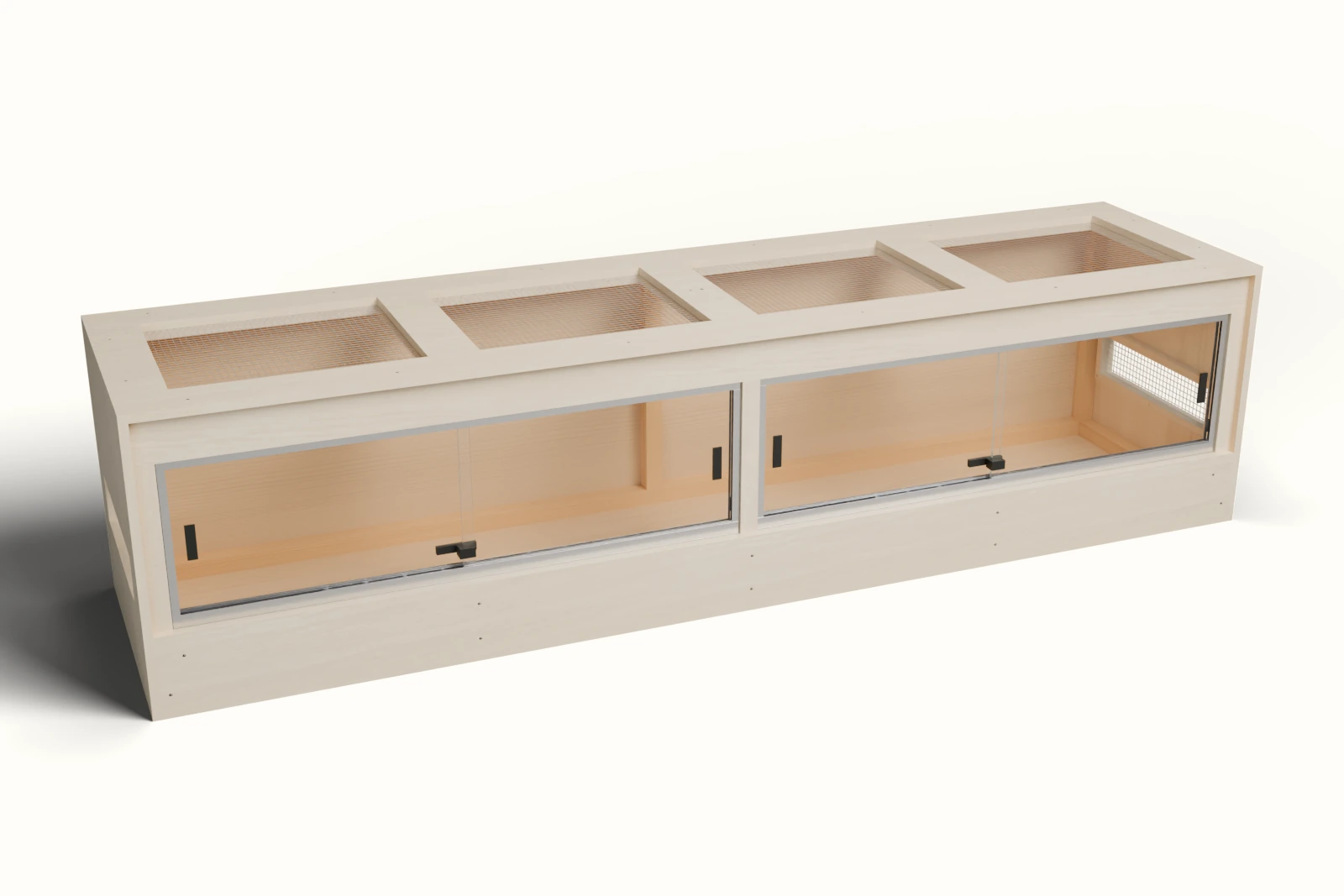
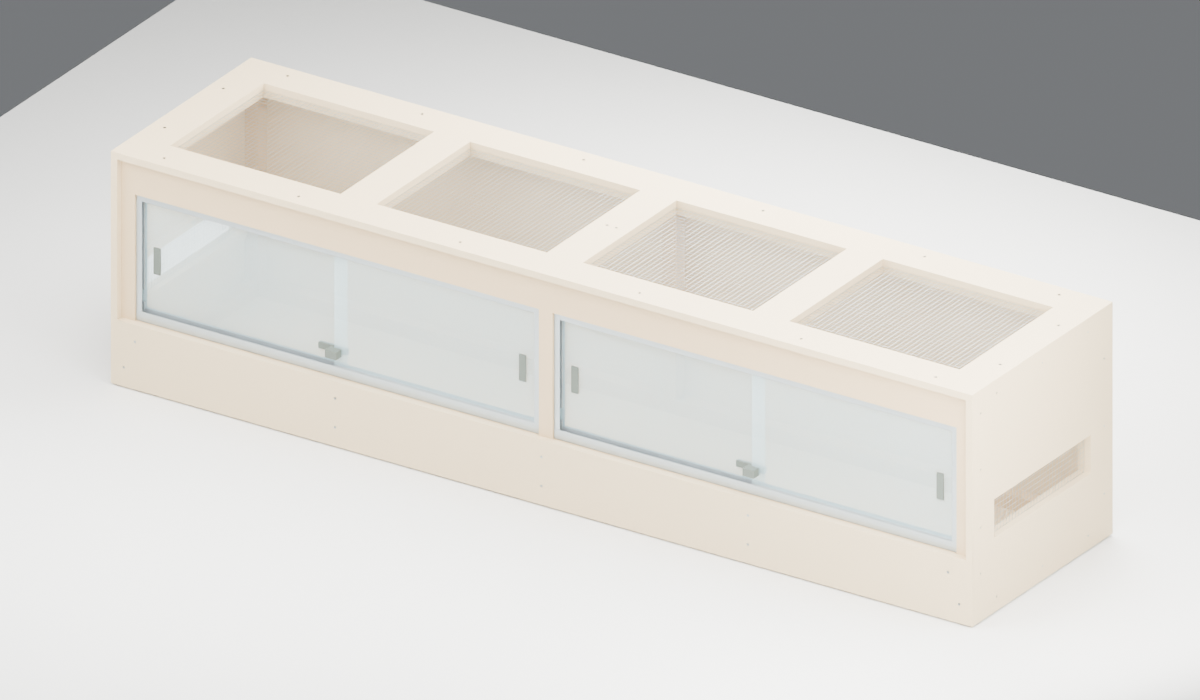
Finish preview: veneer covers the wooden exterior, roof and exposed edges. This full wrap needs revised veneer quantities, core cuts and door clearances before construction; it is not included in this guide’s cut list. Natural grain and color vary by sheet.
About these previews
Rendered from this enclosure’s own construction model, using maple, white oak or walnut textures on the exterior surfaces. Added veneer and edge-band thickness is not modeled here. Construction steps, dimensions, shopping quantities, PDF and 3D reference remain the reviewed guide. Confirm the selected veneer, adhesive, balanced panel treatment and hardware clearances in a coordinated construction revision before building the full wrap.
Texture scans by Jenelle van Heerden via Poly Haven: Maple, White oak, Walnut. CC0 texture license. The scans illustrate natural wood and are not samples from the veneer supplier’s current batch.
A picture-led plan for the wooden shell, four sliding glass panes and six replaceable screens. The solid supports stay at their purchased thickness. Follow the short numbered operations and open the workshop details when a step calls for them.
Indoor dry shell only. No wet basin, saturated substrate, stacking, casters, outdoor use, roof climbing or equipment supported by mesh.
Follow the build in 3D
Complete enclosure
More model controls
Select a part for its name and ID.
About the model
Temporary clamps and supports appear in the step pictures. Early cutting stages show finished-part references, not a moving cutter. Track internals and lock contours are schematic. Received-profile capture, locking and glazing trials are required. Both rear leaves slide in the open-door view after lock bodies are removed; carriers move at half speed. Roofs are removable, right first, while the frame stays fixed.
Before cutting: Stock, glazing and corrosion-compatibility holds remain open. Do not build from the reference hardware sizes.
This is an intermediate to advanced woodworking project. You need accurate sheet cuts, guided recesses, stopped drilling, long-assembly squaring and careful glazing. The pictures explain the work; they do not remove these skills.
Width is left-to-right while facing the front. Local screen rings, backers, channels and fixings reduce usable space in their locations. Pulls/locks project beyond the wooden body. Planning space is not a heat clearance.
Before purchasing: Confirm the smaller access openings suit your maintenance needs. The center post stays fixed. Obtain actual contents, full support and building-floor evidence separately. No capacity, species suitability or enclosure performance is established.
Find the next operation
N11 · ILLUSTRATED PLAN
Start here
Follow the numbered pictured actions in order. Exact buying, cuts and drilling details stay in the references so they do not crowd each step.
Use a flat 112 ×36 in (2844.8 ×914.4 mm) supported bench with a clear walk-around route and separate clean glass/curing area. Rehearse the actual tools and clamps on the dry assembly before glue.
Have ready
Purpose
Tape, square, straightedge, caliper and moisture meter
Measure sound stock; record actual thickness and stabilized workshop conditions.
Supported saw and guides, blade suited to sheet stock
Rough cuts, finished square cuts and repeatable full-section crosscuts.
Guided router, straight bit, templates and chisel
Roof overlap, rib bearing seats and vent/ring openings.
Stopped drill, countersink, hand driver and actual trial bits
11/64 in #8 clearance;7/64 in starting #8 pilot;1/8 in #4 clearance and 1/16 in starting #4 pilot. Verify receiver trials.
Two clamps with≥98 in clear opening; four 30 in clamps; protective half-inch cauls
Long/depth squaring; actual jaw/throat/tool access must be rehearsed. Temporary braces retain loose walls.
Stable padded turning cradle and three helpers
Empty-shell inversion and supported handling; verify actual mass and helper capacity.
Metal cutting/deburring setup, mesh snips and wire gloves
Matched steel rails, chip cleanup and captured wire edges. No gloves near rotating cutters.
Glazing handling gear and supplier help
No drilling or sizing tempered panes in the workshop.
Abrasives, brushes, masking, ventilation and required PPE
Follow your actual tool manuals and product labels; keep adhesive/coating stages separate.
Active work time depends on skills and tools. Plan separate stock stabilization, trials, glue holds, finish cure and track/sealant cure. Do not infer a weekend completion time.
N11 · ILLUSTRATED PLAN
Check and prepare · 1 OF 32
1. Check the delivered wood
Parts: Parts identified in the picture and linked workshop reference; complete IDs in the source schedule.
Have ready: Caliper, tape, square, straightedge, moisture meter
Before you start: Do not start cutting from nominal labels.
Check the delivered wood. Picture explains the action; use the linked drawing for exact settings.
Measure each sheet at several points. The reference plywood is 0.70312 in (17.86 mm). Enter the actual batch thickness in the source and regenerate the parts before cutting.
Each sheet needs at least 96.3125 in (2446.34 mm) ×47.59375 in (1208.88 mm) before the stated squaring cuts. Check the complete layouts, including defects.
Select straight, dry untreated boards:2 ×2 means actual 1.5 ×1.5 in;2 ×4 means actual 1.5 ×3.5 in. Reject splits, loose knots, wane and twisted bearing faces. Record dimensions and stable moisture readings for the workshop.
Check before continuing: Receiving record complete; layouts and regenerated dimensions agree with your actual material.
Watch out: A nominal 3/4 in label does not mean 0.750 in.
Have ready: Matched track samples, scrap wood, caliper, lock and safety-glass sample
Before you start: Do not order glass before the full finished-frame trial.
Check the sliding-door kit. Picture explains the action; use the linked drawing for exact settings.
Check 993 upper channels,999 lower rails,995 shoes and 997 carriers are the same steel Roll-Ezy system. Do not substitute plastic, aluminum or a different profile.
Trial the actual shoe and scant 6 mm glass, both running lanes, cushions, removable lift blocks and 963L lock. Use a supplier-handled sample; do not force a pane into a channel.
Reserve matching wood/metal offcuts for the glue and coating trials. Record actual lane sizes, lock projections and the removal sequence.
Check before continuing: The receiving worksheet identifies every delivered model and each unresolved measurement.
Watch out: Matching exterior sizes do not prove matching running channels.
Parts: Parts identified in the picture and linked workshop reference; complete IDs in the source schedule.
Have ready: Full cutting diagrams, measured saw kerf, supported saw setup
Before you start: Inspect defects before accepting the layout.
Plan the three sheets. Picture explains the action; use the linked drawing for exact settings.
Lay out all rough blanks with the face-grain arrows. Sheet 1 holds the floor and back. Sheet 2 holds the left roof and side, all screen rings and the backer straps. Sheet 3 holds the right roof and side and the retaining face.
Square the long reference edge and one end. The plan reserves 0.125 in (3.17 mm) at each edge and 0.125 in (3.17 mm) between cuts.
Rip the listed rows first, then crosscut each row into blanks. Rip means make a piece narrower; crosscut means shorten it. Keep sound trial offcuts.
Check before continuing: Every rough blank fits its marked usable sheet; no grain direction is rotated.
Watch out: Do not subtract saw kerf from the required finished part.
Parts: Parts identified in the picture and linked workshop reference; complete IDs in the source schedule.
Have ready: Supported saw, guides, square, pencil
Before you start: Support the full sheet and waste; follow your saw manual and keep hands out of the cut.
Cut and label the plywood. Picture explains the action; use the linked drawing for exact settings.
Cut rough blanks in the planned sequence, then finish each to the exact cut schedule. Measure from the same square edges each time.
Label the part ID, FRONT, BOTTOM and INSIDE before turning a piece over. Mark the reference face and the two measuring edges shown on its drawing.
Match paired sides and roof depths within 0.010 in (0.254 mm). Panel length/width target is±1/64 in (±0.397 mm), subject to the tighter mating-part checks.
Check before continuing: Finished sizes, quantities and orientation agree with the cut list.
Parts: Parts identified in the picture and linked workshop reference; complete IDs in the source schedule.
Have ready: Crosscut saw with stop/support, square, part labels
Before you start: Use a carrier or stop setup for short blocks; never hold them beside a moving blade.
Cut the solid supports. Picture explains the action; use the linked drawing for exact settings.
Use the two 2 ×4 boards for the sill and header. Use the five 2 ×2 boards for posts, cleats, blocks and roof ribs.
Follow the linear-stock diagrams, including end squaring and kerf. Crosscut the long members before the small blocks.
These supports retain their purchased thickness and width. No planing or resawing is specified. A different actual section requires recalculating the source.
Check before continuing: All members are square and correctly labeled; the bearing faces are sound.
Watch out: Do not buy shorter precut studs in place of 96 in boards.
Have ready: Tape, square, flat supported bench, clamps and spacers
Before you start: Keep the rear edges of both sides square. Do not rout a back recess.
Check the square-edged back. Picture explains the action; use the linked drawing for exact settings.
Set the sides at the floor edges and support them with clamps. The back fits BETWEEN the sides, with its outer face flush with their rear edges.
For the reference plywood batch, the back is 94 19/32 in (2402.68 mm) wide and 22 19/32 in (573.88 mm) high. Confirm the measured clear distance between the sides before assembly; do not force an oversize back.
Keep the back bottom level with both side bottoms. The rear posts and rails support the back fastening; screws do not go into the plywood edges.
Check before continuing: Both rear corners meet squarely with no step or recess in either side. All three panel bottoms line up.
Watch out: Measure between the inside side faces, not across their outside edges.
Parts: Front sill S01 · Front header S02 · Upper back rail S50T · Roof rib 1 S601 · Roof rib 2 S602 · Roof rib 3 S603
Have ready: Guided router, square, chisel, stop setup
Before you start: Trial one complete bearing joint before machining the six ends.
Prepare the roof-rib seats. Picture explains the action; use the linked drawing for exact settings.
Mark the three rib centers from the left body datum:25,48 and 71 in (635,1219.2 and 1803.4 mm). Use the exact seat positions on the member drawings.
Make each rail seat 0.5 in (12.7 mm) into its width and 0.75 in (19.05 mm) down from its top. Remove the lower 0.75 in from the last 0.5 in of each rib end.
The remaining upper end rests on the seat floor. Check the rib tops finish level with the supporting rails; drill only after the clamped dry fit.
Check before continuing: All six ends bear fully; none hangs from a screw alone.
Watch out: Do not reverse an end notch or cut the entire rib end away.
Have ready: Guided router, depth measurement, offcut coating trial
Before you start: Confirm the left/right labels before removing either face.
Make the roof overlap. Picture explains the action; use the linked drawing for exact settings.
At the center seam, leave the LEFT lower tongue and RIGHT upper tongue. The overlap is 0.5 in (12.7 mm). Use the exact face/depth settings in the machining reference.
The nominal removal is 0.36156 in (9.18 mm) deep. Its allowance leaves room for finish; trial both coated offcuts first.
Keep the outside roof faces level when seated. The roofs remain removable. Do not glue the overlap or drive screws through its thin tongues.
Check before continuing: The cured sample slides together without force and leaves no more than 1/32 in (0.794 mm) local seated gap.
Watch out: Removing the same face from both halves makes a step instead of an overlap.
Parts: Parts identified in the picture and linked workshop reference; complete IDs in the source schedule.
Have ready: Guided router/jigsaw, templates, square, support
Before you start: Keep the cutout supported. Cut-wire handling comes later.
Cut the vent and ring openings. Picture explains the action; use the linked drawing for exact settings.
Mark the side vent from the wall FRONT edge: 3.75 in (95.25 mm). Mark its bottom 7 in (177.8 mm) above the finished wall bottom. Each side opening is 16.5 in (419.1 mm) ×4 in (101.6 mm).
Mark the four 19 ×16 in (482.6 ×406.4 mm) roof openings using the roof drawings. Preserve the center overlap and all webs.
Cut matching through-openings in the six one-piece screen rings. Each ring overlaps its opening by 3/4 in (19.05 mm). Smooth and seal every cut edge later.
Check before continuing: Vent/ring pairs match, supports remain intact and no ring crosses a backer strap or roof rib.
Watch out: Do not enlarge openings into the frame or rib lands.
Parts: Parts identified in the picture and linked workshop reference; complete IDs in the source schedule.
Have ready: Trial screws, stopped drill, clearance/pilot bits, clamps
Before you start: A clearance hole goes through the first piece; a pilot is the smaller hole in the receiving wood.
Trial the screws and mark holes. Picture explains the action; use the linked drawing for exact settings.
Use the exact fastener schedule and drawing datums. Transfer receiver holes during the clamped dry fit; do not build a chain of hole-to-hole measurements.
For #8 screws, start the receiving trial at 7/64 in (2.778 mm); clearance is 11/64 in (4.366 mm). Confirm with the real screw root and batch. Countersink only enough for a flush head.
Limit each pilot to its listed depth. The schedule checks intermediate wood, joint pockets, screw length and at least 1/16 in (1.588 mm) remaining wood beyond the point in this candidate.
Check before continuing: The offcut joint closes without splitting, a buried point or a crushed veneer.
Watch out: A deep countersink can consume the remaining wood at a thin seat.
Parts: Parts identified in the picture and linked workshop reference; complete IDs in the source schedule.
Have ready: Flat 112 ×36 in bench, square, two≥98 in clamps, four 30 in clamps, protective cauls
Before you start: Have three people for large-piece handling. Keep walls clamped until the back/frame hold them.
Dry-fit the complete wooden shell. Picture explains the action; use the linked drawing for exact settings.
Lay the floor on the fully supported bench. Set sides between floor and roof level; place the back between the square side edges, flush at the rear. Rehearse the front frame, blocks, ribs and removable roofs without glue.
Use half-inch cauls to protect faces. Keep long clamps supported and move one clamp at a time to clear a drilling station. Rehearse the actual clamp jaws and tool body.
Compare both top and front diagonals, measure each opening and check flatness. Project target: diagonal difference no more than 1/16 in (1.588 mm), with every joint fully seated.
Check before continuing: No part requires forcing; actual tool/clamp access and helper roles are rehearsed.
Watch out: Clamps can pull a wrong-sized assembly together while hiding a bad cut.
Parts: Parts identified in the picture and linked workshop reference; complete IDs in the source schedule.
Have ready: Clamps, wood glue, stopped drill, W200 screws
Before you start: Glue only clean bare wood. Do not rely on glue as a certified structural adhesive.
Fit the side cleats and rear posts. Picture explains the action; use the linked drawing for exact settings.
Clamp each side flat on the bench. Seat its upper/lower cleats and rear corner post in the locations on the part drawings, leaving the vent clear.
Spread Titebond III on the mating faces and drive the listed screws from the outward side into the solid supports. Keep the heads flush.
Set the sides on the floor with temporary braces. Keep the floor interface clamped and follow the measured dry-fit positions.
Check before continuing: Both sides have the same finished height and the rear posts leave a clear, square opening for the back.
Watch out: Do not coat glue lands or leave side walls standing unsupported.
Allow time: Manufacturer open assembly 8–10 min; total 20–25 min at 70°F/50%RH. Keep stressed joints clamped 24 h; do not stress a new joint for at least 24 h.
Parts: Full back P04 · Lower back rail S50B · Upper back rail S50T · Center back post S51
Have ready: Clamps, wood glue, W200 screws, square
Before you start: Support the back before loosening a wall brace.
Fit the back and its rails. Picture explains the action; use the linked drawing for exact settings.
Clamp the two back rails and center back post to the back, using the drawing locations. Keep the rib seats facing upward.
Glue the bare mating faces and fasten through the back into those solids. Set the back between the sides and onto the floor, with its inside face against the rear posts and its outside face flush with the side rear edges.
Recheck diagonals before driving the screws into the rear corner posts. Use the listed offset stations so side and back screws do not meet.
Check before continuing: Back is flush at both rear corners, case square and all receiver pilots stop inside solid wood.
Watch out: Do not assume a thin removable back would supply this same racking path.
Allow time: Hold stressed glue joints 24 h, longer if actual label/environment requires.
Parts: Parts identified in the picture and linked workshop reference; complete IDs in the source schedule.
Have ready: Helpers, clamps, glue, W200 screws, square
Before you start: The center post is permanent. Keep all temporary supports until the frame is fixed.
Fit the frame and retaining face. Picture explains the action; use the linked drawing for exact settings.
Seat the sill on all five blocks, with the frame ends between the sides. Use the rehearsed side fixing stations to locate the rails and end posts.
Fit the retaining face across the floor front. Its reference height is 6 in (152.4 mm); glue the bare mating lands and screw into the sill and five blocks.
Recheck body width, diagonals and both openings before glue cures. Side screws into rail ends locate the frame; no end-grain screw capacity is claimed.
Check before continuing: The retaining face has continuous upper support and five supported lower stations; the frame is square.
Watch out: Do not use the retaining board as a step or lifting handle.
Allow time: Keep clamped for the required glue hold before handling.
Have ready: Clamps, W125 screws, depth-stopped drill
Before you start: Do not overdrill the thin bearing ends or use the mesh as a support.
Seat the three roof ribs. Picture explains the action; use the linked drawing for exact settings.
Place each rib’s notched ends on their matching header/back-rail seats. Tops align with the roof support plane.
Drive one #8 ×1.25 in screw at each end, through the remaining 0.75 in rib end into 0.5 in receiving wood. Use the listed pilot depth and countersink trial.
Dry-fit both roofs again. Confirm the screen rings clear the ribs and the right roof can lift free before the left.
Check before continuing: Six bearing ends fully seated; roofs lie flat without being forced down.
Watch out: A screw cannot replace a missing bearing seat.
Parts: Parts identified in the picture and linked workshop reference; complete IDs in the source schedule.
Have ready: Three helpers, clamped rigid cradle, bench, W200 screws
Before you start: Turn only the empty cured shell. Clamp the floor to the case before the turn.
Fasten the floor from above after turning. Picture explains the action; use the linked drawing for exact settings.
Remove loose roofs and fittings. Put padded temporary cross supports on the bench at X13,48 and 83 in (330.2,1219.2 and 2108.2 mm). They span the header-to-back support plane.
With three helpers, turn the clamped empty case upside down onto those supports. The fixed rim/ribs bear on the cradle; the floor underside faces upward. Prevent rolling and sliding with stops/clamps.
Drive the listed floor screws downward from this exposed face into lower cleats, rear posts and five blocks. Check all buried points, then return the supported empty shell upright.
Check before continuing: Floor fixings are complete without drilling beneath a flat board or an unstable lifted case.
Watch out: Never attempt the turn with substrate, glass or loose roof panels installed.
Parts: Parts identified in the picture and linked workshop reference; complete IDs in the source schedule.
Have ready: Abrasives 120–220, vacuum, masking, trial pieces
Before you start: Do not dismantle glued structural joints.
Prepare the wood for coating. Picture explains the action; use the linked drawing for exact settings.
Remove the loose roofs and screen rings. Sand exposed wood progressively 120 to 220 grit; ease sharp edges lightly and clean dust from corners and holes.
Mask the exact bare-wood steel-track bond lands on sill/header/jambs. Keep hardware, running surfaces and future adhesive contact clean.
Test the selected coating and sealant on the actual wood and planned cleaner. Reject weak adhesion or incompatibility; record the accepted system.
Check before continuing: All cut edges and holes are accessible; masked bonding lands remain clean bare wood.
Watch out: Silicone contamination can prevent coating or adhesive from bonding.
Parts: Parts identified in the picture and linked workshop reference; complete IDs in the source schedule.
Have ready: Varathane 284473, synthetic brush, ventilation, film check
Before you start: Indoor dry use only. This coating is not a waterproof tank liner.
Coat the shell and let it cure. Picture explains the action; use the linked drawing for exact settings.
Apply the selected finish to exposed faces, cut edges, holes and removable pieces. Stir, do not shake. Use the product’s thick even coat; target 9 mil wet to 3 mil dry rather than wiping on an unmeasured thin film.
Apply two extra coats to the dry-basin contact faces only after the required recoat interval and 220-grit preparation. Keep masked track lands bare.
Record temperature/humidity, last coat time and full-cure end. Keep coated roof samples: they must still fit without forcing.
Check before continuing: Coating is fully cured and the actual trial passes; odor or dry-to-touch alone is not acceptance.
Watch out: Do not substitute a mildew-additive outdoor finish or call low-VOC animal-safe.
Allow time: VAR-35: about 2 h recoat,48 h light handling,7 days full cure at 70°F/50%RH; cooler/damper conditions need longer. Follow the delivered label if it is more restrictive.
Parts: Parts identified in the picture and linked workshop reference; complete IDs in the source schedule.
Have ready: Deburred profiles, bare-wood bond lands, PL Premium 1390595, spacers, clamps
Before you start: Keep adhesive out of rolling channels. Do not drill fasteners through the anvils.
Bond the matched tracks. Picture explains the action; use the linked drawing for exact settings.
Final-size the continuous rails and jamb channels against the finished frame at the named checkpoint. Keep reference end allowances and cured bond-bed thickness in the calculation.
Clean wood/galvanized contact surfaces as the adhesive instructions require. Apply a continuous supporting bond; align upper/lower lanes vertically with the actual sample gauge.
Brace the profiles without twisting them. Trial lock clearance and any required divider relief on a sample before altering the actual jamb.
Check before continuing: Both bays have straight aligned lanes and a recorded cured outside-face opening.
Watch out: A screw in a rolling path or a crooked lower rail can damage the shoe or glass.
Allow time: PL Premium: brace≥24 h; reserve 48 h at 78°F/50%RH before loading, longer if actual conditions require. Complete the real wood/metal bond trial.
Parts: Parts identified in the picture and linked workshop reference; complete IDs in the source schedule.
Have ready: Actual cushions, tracks, lock, sample glass, caliper, fabricator order sheet
Before you start: Do not order from the reference pane dimensions alone.
Measure the finished bays and order glass. Picture explains the action; use the linked drawing for exact settings.
Install/transfer the actual cushion tabs at the two jambs of each bay. Check the 963L clip and bar clear the delivered channels through the whole travel.
Measure each cured track outside-face opening and each cushioned closing width. Pane width=(closing width+1 in overlap)/2; pane height=outside-face opening−1.25 in.
Ask the fabricator to confirm scant 6 mm fit, tempering, polished edges, quantities and tolerances. Four reference panes are 22.89844 in (581.62 mm) wide ×11.78125 in (299.24 mm) high; no holes. Sign the actual order only after the trial.
Check before continuing: Fabricator-approved final dimensions and trial evidence are recorded for both bays.
Watch out: Tempered panes cannot be cut, drilled or ground to repair a bad order.
Parts: Parts identified in the picture and linked workshop reference; complete IDs in the source schedule.
Have ready: Helpers, glazing handling gear, accepted matched profiles
Before you start: Protect glass edges. Keep lift blocks out until panes are safely seated.
Fit the four glass panes. Picture explains the action; use the linked drawing for exact settings.
Use the fabricator-approved shoe seating method. Insert the rear leaf into its upper lane, lift only enough to clear the lower retaining lip, and settle it onto its carrier. Repeat for the front leaf.
Fit both bays separately. Keep the agreed one-inch overlap and the closing stops; check metal never strikes an exposed glass edge.
Slide slowly by hand through the accepted travel. Stop if a shoe catches, a carrier reaches an end or the frame flexes.
Check before continuing: All four panes are correctly supported, overlap at closing and travel without collision.
Watch out: Do not force a pane into a misaligned lane.
Parts: L side mesh M01L · R side mesh M01R · L side screen ring V01L · R side screen ring V01R
Have ready: Mesh snips, wire-handling gloves, W125 screws, trial
Before you start: Wire gloves are for handling only; keep gloves away from rotating cutters.
Capture the side screens. Picture explains the action; use the linked drawing for exact settings.
Cut the two side screens from the layout. Each is 17.5 in (444.5 mm) ×5 in (127 mm). Flatten the edges; remove loose wires. Predrill wood before placing mesh; snip any fixing-station wire clearance behind the ring, without leaving exposed ends.
Lay each screen against the inside side panel, with a half-inch margin around the opening. Place its one-piece ring over it.
Fasten the ring at its six scheduled stations. Keep the buried points inside the outer panel and every cut wire end behind the ring.
Check before continuing: No loose mesh, projecting wire, trapped corner or contact with a front backer remains.
Watch out: Do not assume this mesh aperture suits every animal or feeder.
Parts: Parts identified in the picture and linked workshop reference; complete IDs in the source schedule.
Have ready: Flat bench, mesh snips, W125 screws
Before you start: Work on each loose roof with its underside facing up.
Capture the roof screens. Picture explains the action; use the linked drawing for exact settings.
Cut four 20 ×17 in (508 ×431.8 mm) screens. Position each with half-inch capture margins. Predrill wood before mesh; keep any snipped screw-station wire ends entirely behind the rings.
Clamp the matching one-piece ring over each screen. Drive its six scheduled screws through clearance holes into the roof, without breaking the top face.
Check the ring positions against rib and lap drawings. Keep equipment weight off the mesh.
Check before continuing: All four screens are flat, replaceable and clear of ribs/roof seams.
Watch out: Do not fasten a screen in place before its coating has fully cured.
Parts: Parts identified in the picture and linked workshop reference; complete IDs in the source schedule.
Have ready: Delivered profiles, accepted sample, stopped drill, TRACK screws
Before you start: Every transferred hole must clear the glass and roller sweep.
Fit the lift blocks, locks and pulls. Picture explains the action; use the linked drawing for exact settings.
Fit the eight HDPE lift blocks to the actual upper lanes. Use their removable web-only fixing stations; recorded trial dimensions govern their width/depth.
At every door position, verify no more than 1/16 in lift and positive lower-shoe capture. Check lock clips cannot spread the leaves apart. Fit one 963L lock per bay and fourFP86 pulls by their instructions.
Remove each lock body before sliding. Rehearse unlocking, removing lift blocks, lifting each pane out and refitting everything. Do not load the shell until the complete closure trial passes.
Check before continuing: Locks, lift prevention and the complete removal/refit path pass the actual trial.
Watch out: A keyed lock alone does not stop a pane lifting out of the tracks.
Have ready: Helpers, W200 screws, hand driver, square
Before you start: Seat left roof first, then right. Do not glue them down.
Fit the removable roofs. Picture explains the action; use the linked drawing for exact settings.
Set the LEFT lower tongue on the center rib. Lower the RIGHT upper tongue onto it; both outside faces finish level.
Drive the eighteen listed roof screws into solid support lands, nine per half. Keep the center fixings outside the thin overlap.
Check every seated edge gap and all screen/frame clearances. For service, remove screws and lift the right roof clear first; the fixed support frame remains in place.
Check before continuing: Both roofs seat flat and can be removed without disturbing the center post or ribs.
Watch out: The viewer’s hide-roof control is not permission to remove structural framing.
Parts: Floor P01 · Dry-bed retaining face P05 · L side P03L · R side P03R · Full back P04
Have ready: Selected DAP00688 silicone, accepted coating coupon, masking
Before you start: HOLD: DAP 00688 excludes use on or near zinc and galvanized metal. This build has zinc hardware. Resolve that conflict with the manufacturers, or revise the system and recheck it, before this operation.
Seal the dry-basin seams. Picture explains the action; use the linked drawing for exact settings.
Proceed only after the documented corrosion-compatibility hold is closed. A coated screw head is not manufacturer approval.
Only after full coating cure, clean and mask the dry-basin seams and lower fixed cleat edges. Use the exact accepted silicone formulation without substituting a mildew-additive product.
Tool continuous nominal 1/4 in (6.35 mm) beads where the seam diagram identifies them. Seal penetrations without covering removable screen/roof parts or sliding channels.
Keep a same-depth cutoff sample. Wait for full through-cure and verify adhesion to the actual coating; record dates and conditions.
Check before continuing: Seams are continuous and accepted samples are cured through, without peeling.
Watch out: A surface skin or an odor check does not establish through-cure.
Allow time: Reserve at least 7 days for the project seam/coupon hold; actual product, bead depth and conditions may require longer. This is a project hold, not an immersion approval.
Parts: Parts identified in the picture and linked workshop reference; complete IDs in the source schedule.
Have ready: Receiving/commissioning records, scales, straightedge, actual equipment instructions
Before you start: Do not add animals or contents until unresolved installation and use holds are resolved.
Check the installation before use. Picture explains the action; use the linked drawing for exact settings.
Verify continuous flat support under the full 96 ×24 in floor. Measure the actual shell, dry bed and equipment mass; check the support and building floor separately. Obtain qualified review where inputs or capacities are uncertain.
Check locks, lift prevention, gaps, exposed wire, fixings, coating and full opening/removal paths. Keep bed depth at or below 4 in (101.6 mm) and side vents unobstructed.
Commission species/feeder containment, ventilation, humidity, protected heat and cable/electrical interfaces against their actual requirements. No species suitability, load capacity or heat clearance comes from this shell guide.
Check before continuing: Every required hold has evidence; prototype/physical/qualified status remains separate from digital checks.
Watch out: Average pounds per square foot does not approve a building floor.
Parts: Parts identified in the picture and linked workshop reference; complete IDs in the source schedule.
Have ready: Soft cleaning tools, accepted cleaner, replacement parts list
Before you start: Empty the shell and safely isolate equipment before service. Never move it filled.
Clean, inspect and service the shell. Picture explains the action; use the linked drawing for exact settings.
Inspect glass edges, tracks, lock clips, lift blocks, screen capture, floor support and coatings regularly and after any equipment or loading change. Stop use if a joint loosens, support settles, glass catches or a finish fails.
For glass service, remove the lock body and lift blocks before lifting an empty pane from its carrier. For roof service, remove the right half before the left; keep frame and ribs fixed.
Clean only with the trial-approved method. Replace damaged screens/rings or worn closures with the same verified system; repair coating fully and allow cure before reuse. Record the work and the new acceptance checks.
Check before continuing: Parts remain replaceable and maintenance does not bypass the original fit, cure or containment checks.
Watch out: Do not slide, lift or relocate the filled assembly.
Exact products and purchase packs are listed separately from installed quantities. Confirm delivery and local availability. Substitutions may change geometry, exposure limits or capacity.
Buy 1 pack/stock unit(s), containing 1 48 x 120 in roll. Planned use/allowance 1; unused pack contents 0.
Reference half-inch aperture and wire stack require receiving verification. Mesh is not containment for every animal/feeder. Six captures, wire edges protected.
No location-qualified total price is claimed. Add taxes, delivery, consumables, tool wear and actual labor. The full wooden parts schedule is separate from purchased stock.
N11 · ILLUSTRATED PLAN
Get ready
Shopping list · continued
Exact products and purchase packs are listed separately from installed quantities. Confirm delivery and local availability. Substitutions may change geometry, exposure limits or capacity.
Conservative coated wood area 147.14508 sq ft; extra two dry-basin coats 51.76562 sq ft. At published practical 50 sq ft/quart, 3.97821 quarts calculated. Purchase 4 quarts in two-quart packs. Each coat/recoat and final full cure follows OP21; no immersion or animal-contact test inferred.
Dry lower-seam and trial allowance: 54 ft at nominal quarter-inch bead plus 20 percent, eight tubes, purchase two six-packs. Exact DAP00688, coating adhesion and through-cure trial at OP30; no standing-water claim. HOLD: manufacturer excludes use on or near zinc/galvanized metal. This build contains zinc screws and tracks. Resolve before purchase/application.
No location-qualified total price is claimed. Add taxes, delivery, consumables, tool wear and actual labor. The full wooden parts schedule is separate from purchased stock.
N11 · ILLUSTRATED PLAN
Get ready
Shopping list · continued
Exact products and purchase packs are listed separately from installed quantities. Confirm delivery and local availability. Substitutions may change geometry, exposure limits or capacity.
Polymershapes smooth black high-density polyethylene (HDPE) sheet HDPE
51962104 · retention
Buy 1 pack/stock unit(s), containing 1 24 x 12 in sheet. Planned use/allowance 1; unused pack contents 0.
Eight nominal capture blocks, two per lane. Reference dimensions in cuts/layout; OP28 measures seated glazing and actual lane before sizing. Machine with a supported carrier; maximum lift 1/16 in while shoe remains captured.
No location-qualified total price is claimed. Add taxes, delivery, consumables, tool wear and actual labor. The full wooden parts schedule is separate from purchased stock.
N11 · ILLUSTRATED PLAN
Get ready
Shopping list · continued
Exact products and purchase packs are listed separately from installed quantities. Confirm delivery and local availability. Substitutions may change geometry, exposure limits or capacity.
Reference sizes only. Do not order before OP23 receiving/finished-frame trial. No cutting or drilling after tempering.
No location-qualified total price is claimed. Add taxes, delivery, consumables, tool wear and actual labor. The full wooden parts schedule is separate from purchased stock.
N11 · ILLUSTRATED PLAN
Get ready
Shopping list · continued
Exact products and purchase packs are listed separately from installed quantities. Confirm delivery and local availability. Substitutions may change geometry, exposure limits or capacity.
No heater, lighting, stand, habitat or animal safety is inferred.
No location-qualified total price is claimed. Add taxes, delivery, consumables, tool wear and actual labor. The full wooden parts schedule is separate from purchased stock.
Cut list
N11 · ILLUSTRATED PLAN
Prepare the parts
Cut list
One of each ID. Read u/v from the named part drawing. Finished sizes govern; blanks include their stated finishing allowance. Saw kerf falls between blanks. Reference hardware/glass sizes remain on hold until the named receiving checkpoint.
Part / material
Thickness
Finished u × v
Rough u × v
P01 Floor PLY
45/64 in (17.86 mm)
96 in (2438.4 mm) × 24 in (609.6 mm)
96 1/16 in (2439.99 mm) × 24 1/32 in (610.39 mm)
P03L L side PLY
45/64 in (17.86 mm)
22 19/32 in (573.88 mm) × 24 in (609.6 mm)
22 21/32 in (575.47 mm) × 24 1/32 in (610.39 mm)
P03R R side PLY
45/64 in (17.86 mm)
22 19/32 in (573.88 mm) × 24 in (609.6 mm)
22 21/32 in (575.47 mm) × 24 1/32 in (610.39 mm)
P04 Full back PLY
45/64 in (17.86 mm)
94 19/32 in (2402.68 mm) × 22 19/32 in (573.88 mm)
94 21/32 in (2404.27 mm) × 22 5/8 in (574.67 mm)
P05 Dry-bed retaining face PLY
45/64 in (17.86 mm)
94 19/32 in (2402.68 mm) × 6 in (152.4 mm)
94 21/32 in (2404.27 mm) × 6 1/32 in (153.19 mm)
B1U Post 1 upper backer PLY
45/64 in (17.86 mm)
4 in (101.6 mm) × 1 1/2 in (38.1 mm)
4 1/16 in (103.19 mm) × 1 17/32 in (38.89 mm)
B1D Post 1 lower backer PLY
45/64 in (17.86 mm)
4 in (101.6 mm) × 1 1/2 in (38.1 mm)
4 1/16 in (103.19 mm) × 1 17/32 in (38.89 mm)
Plywood panel target±1/64 in; matched members within 0.010 in. Joint depths±0.005 in. These are project shop targets, not allowable capacities. Received profiles, glazing tolerance and the cured roof sample govern their own fits. The CSV also retains faces, grain, machining, holes, handedness and assembly references.
N11 · ILLUSTRATED PLAN
Prepare the parts
Cut list · continued
One of each ID. Read u/v from the named part drawing. Finished sizes govern; blanks include their stated finishing allowance. Saw kerf falls between blanks. Reference hardware/glass sizes remain on hold until the named receiving checkpoint.
Part / material
Thickness
Finished u × v
Rough u × v
B2U Post 2 upper backer PLY
45/64 in (17.86 mm)
4 in (101.6 mm) × 1 1/2 in (38.1 mm)
4 1/16 in (103.19 mm) × 1 17/32 in (38.89 mm)
B2D Post 2 lower backer PLY
45/64 in (17.86 mm)
4 in (101.6 mm) × 1 1/2 in (38.1 mm)
4 1/16 in (103.19 mm) × 1 17/32 in (38.89 mm)
B3U Post 3 upper backer PLY
45/64 in (17.86 mm)
4 in (101.6 mm) × 1 1/2 in (38.1 mm)
4 1/16 in (103.19 mm) × 1 17/32 in (38.89 mm)
B3D Post 3 lower backer PLY
45/64 in (17.86 mm)
4 in (101.6 mm) × 1 1/2 in (38.1 mm)
4 1/16 in (103.19 mm) × 1 17/32 in (38.89 mm)
P02L Left roof PLY
45/64 in (17.86 mm)
48 1/4 in (1225.55 mm) × 24 in (609.6 mm)
48 5/16 in (1227.14 mm) × 24 1/32 in (610.39 mm)
P02R Right roof PLY
45/64 in (17.86 mm)
48 1/4 in (1225.55 mm) × 24 in (609.6 mm)
48 5/16 in (1227.14 mm) × 24 1/32 in (610.39 mm)
V01L L side screen ring PLY
45/64 in (17.86 mm)
18 in (457.2 mm) × 5 1/2 in (139.7 mm)
18 1/16 in (458.79 mm) × 5 17/32 in (140.49 mm)
Plywood panel target±1/64 in; matched members within 0.010 in. Joint depths±0.005 in. These are project shop targets, not allowable capacities. Received profiles, glazing tolerance and the cured roof sample govern their own fits. The CSV also retains faces, grain, machining, holes, handedness and assembly references.
N11 · ILLUSTRATED PLAN
Prepare the parts
Cut list · continued
One of each ID. Read u/v from the named part drawing. Finished sizes govern; blanks include their stated finishing allowance. Saw kerf falls between blanks. Reference hardware/glass sizes remain on hold until the named receiving checkpoint.
Part / material
Thickness
Finished u × v
Rough u × v
V01R R side screen ring PLY
45/64 in (17.86 mm)
18 in (457.2 mm) × 5 1/2 in (139.7 mm)
18 1/16 in (458.79 mm) × 5 17/32 in (140.49 mm)
V021 Roof screen ring 1 PLY
45/64 in (17.86 mm)
20 1/2 in (520.7 mm) × 17 1/2 in (444.5 mm)
20 9/16 in (522.29 mm) × 17 17/32 in (445.29 mm)
V022 Roof screen ring 2 PLY
45/64 in (17.86 mm)
20 1/2 in (520.7 mm) × 17 1/2 in (444.5 mm)
20 9/16 in (522.29 mm) × 17 17/32 in (445.29 mm)
V023 Roof screen ring 3 PLY
45/64 in (17.86 mm)
20 1/2 in (520.7 mm) × 17 1/2 in (444.5 mm)
20 9/16 in (522.29 mm) × 17 17/32 in (445.29 mm)
V024 Roof screen ring 4 PLY
45/64 in (17.86 mm)
20 1/2 in (520.7 mm) × 17 1/2 in (444.5 mm)
20 9/16 in (522.29 mm) × 17 17/32 in (445.29 mm)
S01 Front sill RAIL
1 1/2 in (38.1 mm)
94 19/32 in (2402.68 mm) × 3 1/2 in (88.9 mm)
94 21/32 in (2404.27 mm) × 3 1/2 in (88.9 mm)
S02 Front header RAIL
1 1/2 in (38.1 mm)
94 19/32 in (2402.68 mm) × 3 1/2 in (88.9 mm)
94 21/32 in (2404.27 mm) × 3 1/2 in (88.9 mm)
Plywood panel target±1/64 in; matched members within 0.010 in. Joint depths±0.005 in. These are project shop targets, not allowable capacities. Received profiles, glazing tolerance and the cured roof sample govern their own fits. The CSV also retains faces, grain, machining, holes, handedness and assembly references.
N11 · ILLUSTRATED PLAN
Prepare the parts
Cut list · continued
One of each ID. Read u/v from the named part drawing. Finished sizes govern; blanks include their stated finishing allowance. Saw kerf falls between blanks. Reference hardware/glass sizes remain on hold until the named receiving checkpoint.
Part / material
Thickness
Finished u × v
Rough u × v
S101 Sill support block 1 SOLID
1 1/2 in (38.1 mm)
2 1/2 in (63.5 mm) × 1 1/2 in (38.1 mm)
2 9/16 in (65.09 mm) × 1 1/2 in (38.1 mm)
S102 Sill support block 2 SOLID
1 1/2 in (38.1 mm)
2 1/2 in (63.5 mm) × 1 1/2 in (38.1 mm)
2 9/16 in (65.09 mm) × 1 1/2 in (38.1 mm)
S103 Sill support block 3 SOLID
1 1/2 in (38.1 mm)
2 1/2 in (63.5 mm) × 1 1/2 in (38.1 mm)
2 9/16 in (65.09 mm) × 1 1/2 in (38.1 mm)
S104 Sill support block 4 SOLID
1 1/2 in (38.1 mm)
2 1/2 in (63.5 mm) × 1 1/2 in (38.1 mm)
2 9/16 in (65.09 mm) × 1 1/2 in (38.1 mm)
S105 Sill support block 5 SOLID
1 1/2 in (38.1 mm)
2 1/2 in (63.5 mm) × 1 1/2 in (38.1 mm)
2 9/16 in (65.09 mm) × 1 1/2 in (38.1 mm)
S201 Front post 1 SOLID
1 1/2 in (38.1 mm)
13 3/32 in (332.58 mm) × 1 1/2 in (38.1 mm)
13 5/32 in (334.17 mm) × 1 1/2 in (38.1 mm)
S202 Front post 2 SOLID
1 1/2 in (38.1 mm)
13 3/32 in (332.58 mm) × 1 1/2 in (38.1 mm)
13 5/32 in (334.17 mm) × 1 1/2 in (38.1 mm)
Plywood panel target±1/64 in; matched members within 0.010 in. Joint depths±0.005 in. These are project shop targets, not allowable capacities. Received profiles, glazing tolerance and the cured roof sample govern their own fits. The CSV also retains faces, grain, machining, holes, handedness and assembly references.
N11 · ILLUSTRATED PLAN
Prepare the parts
Cut list · continued
One of each ID. Read u/v from the named part drawing. Finished sizes govern; blanks include their stated finishing allowance. Saw kerf falls between blanks. Reference hardware/glass sizes remain on hold until the named receiving checkpoint.
Part / material
Thickness
Finished u × v
Rough u × v
S203 Front post 3 SOLID
1 1/2 in (38.1 mm)
13 3/32 in (332.58 mm) × 1 1/2 in (38.1 mm)
13 5/32 in (334.17 mm) × 1 1/2 in (38.1 mm)
S30L L rear corner post SOLID
1 1/2 in (38.1 mm)
22 19/32 in (573.88 mm) × 1 1/2 in (38.1 mm)
22 21/32 in (575.47 mm) × 1 1/2 in (38.1 mm)
S40LB L lower side cleat SOLID
1 1/2 in (38.1 mm)
19 19/32 in (497.68 mm) × 1 1/2 in (38.1 mm)
19 21/32 in (499.27 mm) × 1 1/2 in (38.1 mm)
S40LT L upper side cleat SOLID
1 1/2 in (38.1 mm)
19 19/32 in (497.68 mm) × 1 1/2 in (38.1 mm)
19 21/32 in (499.27 mm) × 1 1/2 in (38.1 mm)
S30R R rear corner post SOLID
1 1/2 in (38.1 mm)
22 19/32 in (573.88 mm) × 1 1/2 in (38.1 mm)
22 21/32 in (575.47 mm) × 1 1/2 in (38.1 mm)
S40RB R lower side cleat SOLID
1 1/2 in (38.1 mm)
19 19/32 in (497.68 mm) × 1 1/2 in (38.1 mm)
19 21/32 in (499.27 mm) × 1 1/2 in (38.1 mm)
S40RT R upper side cleat SOLID
1 1/2 in (38.1 mm)
19 19/32 in (497.68 mm) × 1 1/2 in (38.1 mm)
19 21/32 in (499.27 mm) × 1 1/2 in (38.1 mm)
Plywood panel target±1/64 in; matched members within 0.010 in. Joint depths±0.005 in. These are project shop targets, not allowable capacities. Received profiles, glazing tolerance and the cured roof sample govern their own fits. The CSV also retains faces, grain, machining, holes, handedness and assembly references.
N11 · ILLUSTRATED PLAN
Prepare the parts
Cut list · continued
One of each ID. Read u/v from the named part drawing. Finished sizes govern; blanks include their stated finishing allowance. Saw kerf falls between blanks. Reference hardware/glass sizes remain on hold until the named receiving checkpoint.
Part / material
Thickness
Finished u × v
Rough u × v
S50B Lower back rail SOLID
1 1/2 in (38.1 mm)
91 19/32 in (2326.48 mm) × 1 1/2 in (38.1 mm)
91 21/32 in (2328.07 mm) × 1 1/2 in (38.1 mm)
S50T Upper back rail SOLID
1 1/2 in (38.1 mm)
91 19/32 in (2326.48 mm) × 1 1/2 in (38.1 mm)
91 21/32 in (2328.07 mm) × 1 1/2 in (38.1 mm)
S51 Center back post SOLID
1 1/2 in (38.1 mm)
19 19/32 in (497.68 mm) × 1 1/2 in (38.1 mm)
19 21/32 in (499.27 mm) × 1 1/2 in (38.1 mm)
S601 Roof rib 1 SOLID
1 1/2 in (38.1 mm)
20 19/32 in (523.08 mm) × 1 1/2 in (38.1 mm)
20 21/32 in (524.67 mm) × 1 1/2 in (38.1 mm)
S602 Roof rib 2 SOLID
1 1/2 in (38.1 mm)
20 19/32 in (523.08 mm) × 1 1/2 in (38.1 mm)
20 21/32 in (524.67 mm) × 1 1/2 in (38.1 mm)
S603 Roof rib 3 SOLID
1 1/2 in (38.1 mm)
20 19/32 in (523.08 mm) × 1 1/2 in (38.1 mm)
20 21/32 in (524.67 mm) × 1 1/2 in (38.1 mm)
T1U Bay 1 upper rail KV993
15/16 in (23.81 mm)
44 59/64 in (1141.02 mm) × 5/8 in (15.88 mm)
Receiving checkpoint OP23 / OP28
Plywood panel target±1/64 in; matched members within 0.010 in. Joint depths±0.005 in. These are project shop targets, not allowable capacities. Received profiles, glazing tolerance and the cured roof sample govern their own fits. The CSV also retains faces, grain, machining, holes, handedness and assembly references.
N11 · ILLUSTRATED PLAN
Prepare the parts
Cut list · continued
One of each ID. Read u/v from the named part drawing. Finished sizes govern; blanks include their stated finishing allowance. Saw kerf falls between blanks. Reference hardware/glass sizes remain on hold until the named receiving checkpoint.
Part / material
Thickness
Finished u × v
Rough u × v
T1L Bay 1 lower rail KV999
1 in (25.4 mm)
44 59/64 in (1141.02 mm) × 1 in (25.4 mm)
Receiving checkpoint OP23 / OP28
T1JL Bay 1 L jamb channel KV993
15/16 in (23.81 mm)
11 13/32 in (289.72 mm) × 5/8 in (15.88 mm)
Receiving checkpoint OP23 / OP28
T1JR Bay 1 R jamb channel KV993
15/16 in (23.81 mm)
11 13/32 in (289.72 mm) × 5/8 in (15.88 mm)
Receiving checkpoint OP23 / OP28
G1L Bay 1 L glass GLASS
0.23622 in (6 mm)
22.89844 in (581.62 mm) × 11 25/32 in (299.24 mm)
Receiving checkpoint OP23 / OP28
D1LS Bay 1 L shoe KV995
21/64 in (8.33 mm)
22.89844 in (581.62 mm) × 7/16 in (11.11 mm)
Receiving checkpoint OP23 / OP28
D1LC Bay 1 L carrier KV997
3/8 in (9.52 mm)
33.84766 in (859.73 mm) × 17/32 in (13.49 mm)
Receiving checkpoint OP23 / OP28
A1L1 Bay 1 L lift block 1 HDPE
5/16 in (7.94 mm)
22.39844 in (568.92 mm) × 11/32 in (8.73 mm)
Receiving checkpoint OP23 / OP28
Plywood panel target±1/64 in; matched members within 0.010 in. Joint depths±0.005 in. These are project shop targets, not allowable capacities. Received profiles, glazing tolerance and the cured roof sample govern their own fits. The CSV also retains faces, grain, machining, holes, handedness and assembly references.
N11 · ILLUSTRATED PLAN
Prepare the parts
Cut list · continued
One of each ID. Read u/v from the named part drawing. Finished sizes govern; blanks include their stated finishing allowance. Saw kerf falls between blanks. Reference hardware/glass sizes remain on hold until the named receiving checkpoint.
Part / material
Thickness
Finished u × v
Rough u × v
A1L2 Bay 1 L lift block 2 HDPE
5/16 in (7.94 mm)
22.39844 in (568.92 mm) × 11/32 in (8.73 mm)
Receiving checkpoint OP23 / OP28
G1R Bay 1 R glass GLASS
0.23622 in (6 mm)
22.89844 in (581.62 mm) × 11 25/32 in (299.24 mm)
Receiving checkpoint OP23 / OP28
D1RS Bay 1 R shoe KV995
21/64 in (8.33 mm)
22.89844 in (581.62 mm) × 7/16 in (11.11 mm)
Receiving checkpoint OP23 / OP28
D1RC Bay 1 R carrier KV997
3/8 in (9.52 mm)
33.84766 in (859.73 mm) × 17/32 in (13.49 mm)
Receiving checkpoint OP23 / OP28
A1R1 Bay 1 R lift block 1 HDPE
5/16 in (7.94 mm)
22.39844 in (568.92 mm) × 11/32 in (8.73 mm)
Receiving checkpoint OP23 / OP28
A1R2 Bay 1 R lift block 2 HDPE
5/16 in (7.94 mm)
22.39844 in (568.92 mm) × 11/32 in (8.73 mm)
Receiving checkpoint OP23 / OP28
C1LL Bay 1 L cushion L PAD
1/16 in (1.59 mm)
11 13/32 in (289.72 mm) × 0.28 in (7.11 mm)
Receiving checkpoint OP23 / OP28
Plywood panel target±1/64 in; matched members within 0.010 in. Joint depths±0.005 in. These are project shop targets, not allowable capacities. Received profiles, glazing tolerance and the cured roof sample govern their own fits. The CSV also retains faces, grain, machining, holes, handedness and assembly references.
N11 · ILLUSTRATED PLAN
Prepare the parts
Cut list · continued
One of each ID. Read u/v from the named part drawing. Finished sizes govern; blanks include their stated finishing allowance. Saw kerf falls between blanks. Reference hardware/glass sizes remain on hold until the named receiving checkpoint.
Part / material
Thickness
Finished u × v
Rough u × v
C1LR Bay 1 L cushion R PAD
1/16 in (1.59 mm)
11 13/32 in (289.72 mm) × 0.28 in (7.11 mm)
Receiving checkpoint OP23 / OP28
C1RL Bay 1 R cushion L PAD
1/16 in (1.59 mm)
11 13/32 in (289.72 mm) × 0.28 in (7.11 mm)
Receiving checkpoint OP23 / OP28
C1RR Bay 1 R cushion R PAD
1/16 in (1.59 mm)
11 13/32 in (289.72 mm) × 0.28 in (7.11 mm)
Receiving checkpoint OP23 / OP28
T2U Bay 2 upper rail KV993
15/16 in (23.81 mm)
44 59/64 in (1141.02 mm) × 5/8 in (15.88 mm)
Receiving checkpoint OP23 / OP28
T2L Bay 2 lower rail KV999
1 in (25.4 mm)
44 59/64 in (1141.02 mm) × 1 in (25.4 mm)
Receiving checkpoint OP23 / OP28
T2JL Bay 2 L jamb channel KV993
15/16 in (23.81 mm)
11 13/32 in (289.72 mm) × 5/8 in (15.88 mm)
Receiving checkpoint OP23 / OP28
T2JR Bay 2 R jamb channel KV993
15/16 in (23.81 mm)
11 13/32 in (289.72 mm) × 5/8 in (15.88 mm)
Receiving checkpoint OP23 / OP28
Plywood panel target±1/64 in; matched members within 0.010 in. Joint depths±0.005 in. These are project shop targets, not allowable capacities. Received profiles, glazing tolerance and the cured roof sample govern their own fits. The CSV also retains faces, grain, machining, holes, handedness and assembly references.
N11 · ILLUSTRATED PLAN
Prepare the parts
Cut list · continued
One of each ID. Read u/v from the named part drawing. Finished sizes govern; blanks include their stated finishing allowance. Saw kerf falls between blanks. Reference hardware/glass sizes remain on hold until the named receiving checkpoint.
Part / material
Thickness
Finished u × v
Rough u × v
G2L Bay 2 L glass GLASS
0.23622 in (6 mm)
22.89844 in (581.62 mm) × 11 25/32 in (299.24 mm)
Receiving checkpoint OP23 / OP28
D2LS Bay 2 L shoe KV995
21/64 in (8.33 mm)
22.89844 in (581.62 mm) × 7/16 in (11.11 mm)
Receiving checkpoint OP23 / OP28
D2LC Bay 2 L carrier KV997
3/8 in (9.52 mm)
33.84766 in (859.73 mm) × 17/32 in (13.49 mm)
Receiving checkpoint OP23 / OP28
A2L1 Bay 2 L lift block 1 HDPE
5/16 in (7.94 mm)
22.39844 in (568.92 mm) × 11/32 in (8.73 mm)
Receiving checkpoint OP23 / OP28
A2L2 Bay 2 L lift block 2 HDPE
5/16 in (7.94 mm)
22.39844 in (568.92 mm) × 11/32 in (8.73 mm)
Receiving checkpoint OP23 / OP28
G2R Bay 2 R glass GLASS
0.23622 in (6 mm)
22.89844 in (581.62 mm) × 11 25/32 in (299.24 mm)
Receiving checkpoint OP23 / OP28
D2RS Bay 2 R shoe KV995
21/64 in (8.33 mm)
22.89844 in (581.62 mm) × 7/16 in (11.11 mm)
Receiving checkpoint OP23 / OP28
Plywood panel target±1/64 in; matched members within 0.010 in. Joint depths±0.005 in. These are project shop targets, not allowable capacities. Received profiles, glazing tolerance and the cured roof sample govern their own fits. The CSV also retains faces, grain, machining, holes, handedness and assembly references.
N11 · ILLUSTRATED PLAN
Prepare the parts
Cut list · continued
One of each ID. Read u/v from the named part drawing. Finished sizes govern; blanks include their stated finishing allowance. Saw kerf falls between blanks. Reference hardware/glass sizes remain on hold until the named receiving checkpoint.
Part / material
Thickness
Finished u × v
Rough u × v
D2RC Bay 2 R carrier KV997
3/8 in (9.52 mm)
33.84766 in (859.73 mm) × 17/32 in (13.49 mm)
Receiving checkpoint OP23 / OP28
A2R1 Bay 2 R lift block 1 HDPE
5/16 in (7.94 mm)
22.39844 in (568.92 mm) × 11/32 in (8.73 mm)
Receiving checkpoint OP23 / OP28
A2R2 Bay 2 R lift block 2 HDPE
5/16 in (7.94 mm)
22.39844 in (568.92 mm) × 11/32 in (8.73 mm)
Receiving checkpoint OP23 / OP28
C2LL Bay 2 L cushion L PAD
1/16 in (1.59 mm)
11 13/32 in (289.72 mm) × 0.28 in (7.11 mm)
Receiving checkpoint OP23 / OP28
C2LR Bay 2 L cushion R PAD
1/16 in (1.59 mm)
11 13/32 in (289.72 mm) × 0.28 in (7.11 mm)
Receiving checkpoint OP23 / OP28
C2RL Bay 2 R cushion L PAD
1/16 in (1.59 mm)
11 13/32 in (289.72 mm) × 0.28 in (7.11 mm)
Receiving checkpoint OP23 / OP28
C2RR Bay 2 R cushion R PAD
1/16 in (1.59 mm)
11 13/32 in (289.72 mm) × 0.28 in (7.11 mm)
Receiving checkpoint OP23 / OP28
Plywood panel target±1/64 in; matched members within 0.010 in. Joint depths±0.005 in. These are project shop targets, not allowable capacities. Received profiles, glazing tolerance and the cured roof sample govern their own fits. The CSV also retains faces, grain, machining, holes, handedness and assembly references.
N11 · ILLUSTRATED PLAN
Prepare the parts
Cut list · continued
One of each ID. Read u/v from the named part drawing. Finished sizes govern; blanks include their stated finishing allowance. Saw kerf falls between blanks. Reference hardware/glass sizes remain on hold until the named receiving checkpoint.
Part / material
Thickness
Finished u × v
Rough u × v
M01L L side mesh MESH
0.025 in (0.64 mm)
17 1/2 in (444.5 mm) × 5 in (127 mm)
17.5 × 5 in (444.5 × 127 mm)
M01R R side mesh MESH
0.025 in (0.64 mm)
17 1/2 in (444.5 mm) × 5 in (127 mm)
17.5 × 5 in (444.5 × 127 mm)
M021 Roof mesh 1 MESH
0.025 in (0.64 mm)
20 in (508 mm) × 17 in (431.8 mm)
20 × 17 in (508 × 431.8 mm)
M022 Roof mesh 2 MESH
0.025 in (0.64 mm)
20 in (508 mm) × 17 in (431.8 mm)
20 × 17 in (508 × 431.8 mm)
M023 Roof mesh 3 MESH
0.025 in (0.64 mm)
20 in (508 mm) × 17 in (431.8 mm)
20 × 17 in (508 × 431.8 mm)
M024 Roof mesh 4 MESH
0.025 in (0.64 mm)
20 in (508 mm) × 17 in (431.8 mm)
20 × 17 in (508 × 431.8 mm)
Plywood panel target±1/64 in; matched members within 0.010 in. Joint depths±0.005 in. These are project shop targets, not allowable capacities. Received profiles, glazing tolerance and the cured roof sample govern their own fits. The CSV also retains faces, grain, machining, holes, handedness and assembly references.
Cutting diagrams
N11 · ILLUSTRATED PLAN
Prepare the parts
Cutting layout · PLY-1
This is a feasible cutting sequence, not an optimization claim. Measure stock and kerf first; reject defects in required blanks.
Keep the marked grain direction and part IDs. Use supported cuts; small pieces need a carrier. Received hardware and trial pieces are checked before final sizing.
N11 · ILLUSTRATED PLAN
Prepare the parts
Cutting layout · PLY-2
This is a feasible cutting sequence, not an optimization claim. Measure stock and kerf first; reject defects in required blanks.
Keep the marked grain direction and part IDs. Use supported cuts; small pieces need a carrier. Received hardware and trial pieces are checked before final sizing.
N11 · ILLUSTRATED PLAN
Prepare the parts
Cutting layout · PLY-3
This is a feasible cutting sequence, not an optimization claim. Measure stock and kerf first; reject defects in required blanks.
Keep the marked grain direction and part IDs. Use supported cuts; small pieces need a carrier. Received hardware and trial pieces are checked before final sizing.
N11 · ILLUSTRATED PLAN
Prepare the parts
Cutting layout · RAIL
This is a feasible cutting sequence, not an optimization claim. Measure stock and kerf first; reject defects in required blanks.
Keep the marked grain direction and part IDs. Use supported cuts; small pieces need a carrier. Received hardware and trial pieces are checked before final sizing.
N11 · ILLUSTRATED PLAN
Prepare the parts
Cutting layout · SOLID
This is a feasible cutting sequence, not an optimization claim. Measure stock and kerf first; reject defects in required blanks.
Keep the marked grain direction and part IDs. Use supported cuts; small pieces need a carrier. Received hardware and trial pieces are checked before final sizing.
N11 · ILLUSTRATED PLAN
Prepare the parts
Cutting layout · MESH
This is a feasible cutting sequence, not an optimization claim. Measure stock and kerf first; reject defects in required blanks.
Keep the marked grain direction and part IDs. Use supported cuts; small pieces need a carrier. Received hardware and trial pieces are checked before final sizing.
N11 · ILLUSTRATED PLAN
Prepare the parts
Cutting layout · HDPE
This is a feasible cutting sequence, not an optimization claim. Measure stock and kerf first; reject defects in required blanks.
Keep the marked grain direction and part IDs. Use supported cuts; small pieces need a carrier. Received hardware and trial pieces are checked before final sizing.
N11 · ILLUSTRATED PLAN
Prepare the parts
Steel section layout · KV993
Each uses one 144 in stock length in this reference configuration. Actual metal kerf, final frame measurements and profile compatibility govern acceptance.
N11 · ILLUSTRATED PLAN
Prepare the parts
Steel section layout · KV995
Each uses one 144 in stock length in this reference configuration. Actual metal kerf, final frame measurements and profile compatibility govern acceptance.
N11 · ILLUSTRATED PLAN
Prepare the parts
Steel section layout · KV997
Each uses one 144 in stock length in this reference configuration. Actual metal kerf, final frame measurements and profile compatibility govern acceptance.
N11 · ILLUSTRATED PLAN
Prepare the parts
Steel section layout · KV999
Each uses one 144 in stock length in this reference configuration. Actual metal kerf, final frame measurements and profile compatibility govern acceptance.
Workshop drawings and measurements
Use the exact workshop references
N11 · ILLUSTRATED PLAN
Workshop reference
Step pictures explain the action. These drawings and schedules define sizes and locations. They are not printable sizing templates. Never measure a printed picture to make a part.
Mark / term
Meaning
A / B
A outward/show face; B inside. Keep FRONT/BOTTOM labels when turning a piece.
u 0 / v 0
The two finished local measuring edges shown on each drawing. Measure every location from those datums.
X / Y / Z
X right; Y toward back; Z upward, facing the access front.
Blue recess / white opening
Blue removes only stated depth; a white opening goes through full material.
C / P
Clearance through first wood; smaller pilot transferred into receiver during clamped fit.
Entry axis + / −
Drill direction in assembly axes; identify the physical starting face before drilling.
Exact versus reference
Finished wood cuts are exact source values with project tolerance. Hardware and glazing reference geometry needs the identified receiving trial.
Field fit
OP23 measures actual cured track outside faces and cushioned stops; OP28 sizes actual capture blocks. The documented equations replace an unspecified “cut to fit.”
Full cut-list and fastener CSV files retain exact values. Changing material thickness or hardware invalidates them, the drawings, model, illustrations and guide.
Workshop drawing · Overall
N11 · ILLUSTRATED PLAN
Workshop reference
Revision v 5-square-back-02. The complete part drawing set is available in the drawings download. Product contours and temporary tools are explanatory where labeled.
Workshop drawing · Side
N11 · ILLUSTRATED PLAN
Workshop reference
Revision v 5-square-back-02. The complete part drawing set is available in the drawings download. Product contours and temporary tools are explanatory where labeled.
Workshop drawing · Exploded
N11 · ILLUSTRATED PLAN
Workshop reference
Revision v 5-square-back-02. The complete part drawing set is available in the drawings download. Product contours and temporary tools are explanatory where labeled.
Workshop drawing · Front Frame
N11 · ILLUSTRATED PLAN
Workshop reference
Revision v 5-square-back-02. The complete part drawing set is available in the drawings download. Product contours and temporary tools are explanatory where labeled.
Workshop drawing · Back Joint
N11 · ILLUSTRATED PLAN
Workshop reference
Revision v 5-square-back-02. The complete part drawing set is available in the drawings download. Product contours and temporary tools are explanatory where labeled.
Workshop drawing · Rib Seat
N11 · ILLUSTRATED PLAN
Workshop reference
Revision v 5-square-back-02. The complete part drawing set is available in the drawings download. Product contours and temporary tools are explanatory where labeled.
Workshop drawing · Roof Joint
N11 · ILLUSTRATED PLAN
Workshop reference
Revision v 5-square-back-02. The complete part drawing set is available in the drawings download. Product contours and temporary tools are explanatory where labeled.
Workshop drawing · Screen Section
N11 · ILLUSTRATED PLAN
Workshop reference
Revision v 5-square-back-02. The complete part drawing set is available in the drawings download. Product contours and temporary tools are explanatory where labeled.
Workshop drawing · Track Fit
N11 · ILLUSTRATED PLAN
Workshop reference
Revision v 5-square-back-02. The complete part drawing set is available in the drawings download. Product contours and temporary tools are explanatory where labeled.
Workshop drawing · Retention Service
N11 · ILLUSTRATED PLAN
Workshop reference
Revision v 5-square-back-02. The complete part drawing set is available in the drawings download. Product contours and temporary tools are explanatory where labeled.
Workshop drawing · Workholding
N11 · ILLUSTRATED PLAN
Workshop reference
Revision v 5-square-back-02. The complete part drawing set is available in the drawings download. Product contours and temporary tools are explanatory where labeled.
Workshop drawing · Finish Route
N11 · ILLUSTRATED PLAN
Workshop reference
Revision v 5-square-back-02. The complete part drawing set is available in the drawings download. Product contours and temporary tools are explanatory where labeled.
Workshop drawing · Floor P01
N11 · ILLUSTRATED PLAN
Workshop reference
Revision v 5-square-back-02. The complete part drawing set is available in the drawings download. Product contours and temporary tools are explanatory where labeled.
Workshop drawing · Left roof P02L
N11 · ILLUSTRATED PLAN
Workshop reference
Revision v 5-square-back-02. The complete part drawing set is available in the drawings download. Product contours and temporary tools are explanatory where labeled.
Workshop drawing · Right roof P02R
N11 · ILLUSTRATED PLAN
Workshop reference
Revision v 5-square-back-02. The complete part drawing set is available in the drawings download. Product contours and temporary tools are explanatory where labeled.
Workshop drawing · L side P03L
N11 · ILLUSTRATED PLAN
Workshop reference
Revision v 5-square-back-02. The complete part drawing set is available in the drawings download. Product contours and temporary tools are explanatory where labeled.
Workshop drawing · R side P03R
N11 · ILLUSTRATED PLAN
Workshop reference
Revision v 5-square-back-02. The complete part drawing set is available in the drawings download. Product contours and temporary tools are explanatory where labeled.
Workshop drawing · Full back P04
N11 · ILLUSTRATED PLAN
Workshop reference
Revision v 5-square-back-02. The complete part drawing set is available in the drawings download. Product contours and temporary tools are explanatory where labeled.
Workshop drawing · Dry-bed retaining face P05
N11 · ILLUSTRATED PLAN
Workshop reference
Revision v 5-square-back-02. The complete part drawing set is available in the drawings download. Product contours and temporary tools are explanatory where labeled.
Workshop drawing · Front header S02
N11 · ILLUSTRATED PLAN
Workshop reference
Revision v 5-square-back-02. The complete part drawing set is available in the drawings download. Product contours and temporary tools are explanatory where labeled.
Workshop drawing · Upper back rail S50T
N11 · ILLUSTRATED PLAN
Workshop reference
Revision v 5-square-back-02. The complete part drawing set is available in the drawings download. Product contours and temporary tools are explanatory where labeled.
Workshop drawing · Roof rib 1 S601
N11 · ILLUSTRATED PLAN
Workshop reference
Revision v 5-square-back-02. The complete part drawing set is available in the drawings download. Product contours and temporary tools are explanatory where labeled.
Exact drilling schedule
N11 · ILLUSTRATED PLAN
Workshop reference
All sizes below are inches. u/v are from the first piece’s finished drawing edges. C is diameter × through-stack depth; P is trial starting diameter × receiver-pilot depth. Receiver holes are transferred while clamped. C may include captured mesh spacing; predrill wood before adding wire.
ID / first→receiver
u / v
Entry
C Ø × depth
P Ø × depth
Screw / length
FX001 P03L→S30L
4 / 22.54688
X+
0.17188 × 0.70312
0.10938 × 1.32812
W200 2
FX002 P03L→S30L
11 / 22.54688
X+
0.17188 × 0.70312
0.10938 × 1.32812
W200 2
FX003 P03L→S30L
18 / 22.54688
X+
0.17188 × 0.70312
0.10938 × 1.32812
W200 2
FX004 P03L→S40LB
0.75 / 4.20312
X+
0.17188 × 0.70312
0.10938 × 1.32812
W200 2
FX005 P03L→S40LB
0.75 / 12
X+
0.17188 × 0.70312
0.10938 × 1.32812
W200 2
FX006 P03L→S40LB
0.75 / 19.79688
X+
0.17188 × 0.70312
0.10938 × 1.32812
W200 2
FX007 P03L→S40LT
21.84375 / 4.20312
X+
0.17188 × 0.70312
0.10938 × 1.32812
W200 2
FX008 P03L→S40LT
21.84375 / 12
X+
0.17188 × 0.70312
0.10938 × 1.32812
W200 2
FX009 P03L→S40LT
21.84375 / 19.79688
X+
0.17188 × 0.70312
0.10938 × 1.32812
W200 2
FX010 P03L→S201
9 / 1.45312
X+
0.17188 × 0.70312
0.10938 × 1.32812
W200 2
FX011 P03L→S201
15 / 1.45312
X+
0.17188 × 0.70312
0.10938 × 1.32812
W200 2
FX012 P03L→S01
4.25 / 1.45312
X+
0.17188 × 0.70312
0.10938 × 1.32812
W200 2
FX013 P03L→S02
20.84375 / 1.45312
X+
0.17188 × 0.70312
0.10938 × 1.32812
W200 2
FX014 P03R→S30R
4 / 22.54688
X−
0.17188 × 0.70312
0.10938 × 1.32812
W200 2
FX015 P03R→S30R
11 / 22.54688
X−
0.17188 × 0.70312
0.10938 × 1.32812
W200 2
Countersink flush only after the offcut trial. Metal/HDPE/cushion web holes are separate receiving transfers, not invented manufacturer patterns. Use the exact source CSV for global coordinates and all transfer limits.
Exact drilling schedule · continued
N11 · ILLUSTRATED PLAN
Workshop reference
All sizes below are inches. u/v are from the first piece’s finished drawing edges. C is diameter × through-stack depth; P is trial starting diameter × receiver-pilot depth. Receiver holes are transferred while clamped. C may include captured mesh spacing; predrill wood before adding wire.
ID / first→receiver
u / v
Entry
C Ø × depth
P Ø × depth
Screw / length
FX016 P03R→S30R
18 / 22.54688
X−
0.17188 × 0.70312
0.10938 × 1.32812
W200 2
FX017 P03R→S40RB
0.75 / 4.20312
X−
0.17188 × 0.70312
0.10938 × 1.32812
W200 2
FX018 P03R→S40RB
0.75 / 12
X−
0.17188 × 0.70312
0.10938 × 1.32812
W200 2
FX019 P03R→S40RB
0.75 / 19.79688
X−
0.17188 × 0.70312
0.10938 × 1.32812
W200 2
FX020 P03R→S40RT
21.84375 / 4.20312
X−
0.17188 × 0.70312
0.10938 × 1.32812
W200 2
FX021 P03R→S40RT
21.84375 / 12
X−
0.17188 × 0.70312
0.10938 × 1.32812
W200 2
FX022 P03R→S40RT
21.84375 / 19.79688
X−
0.17188 × 0.70312
0.10938 × 1.32812
W200 2
FX023 P03R→S203
9 / 1.45312
X−
0.17188 × 0.70312
0.10938 × 1.32812
W200 2
FX024 P03R→S203
15 / 1.45312
X−
0.17188 × 0.70312
0.10938 × 1.32812
W200 2
FX025 P03R→S01
4.25 / 1.45312
X−
0.17188 × 0.70312
0.10938 × 1.32812
W200 2
FX026 P03R→S02
20.84375 / 1.45312
X−
0.17188 × 0.70312
0.10938 × 1.32812
W200 2
FX027 P01→S40LB
1.45312 / 4.20312
Z+
0.17188 × 0.70312
0.10938 × 1.32812
W200 2
FX028 P01→S40LB
1.45312 / 19.79688
Z+
0.17188 × 0.70312
0.10938 × 1.32812
W200 2
FX029 P01→S40RB
94.54688 / 4.20312
Z+
0.17188 × 0.70312
0.10938 × 1.32812
W200 2
FX030 P01→S40RB
94.54688 / 19.79688
Z+
0.17188 × 0.70312
0.10938 × 1.32812
W200 2
Countersink flush only after the offcut trial. Metal/HDPE/cushion web holes are separate receiving transfers, not invented manufacturer patterns. Use the exact source CSV for global coordinates and all transfer limits.
Exact drilling schedule · continued
N11 · ILLUSTRATED PLAN
Workshop reference
All sizes below are inches. u/v are from the first piece’s finished drawing edges. C is diameter × through-stack depth; P is trial starting diameter × receiver-pilot depth. Receiver holes are transferred while clamped. C may include captured mesh spacing; predrill wood before adding wire.
ID / first→receiver
u / v
Entry
C Ø × depth
P Ø × depth
Screw / length
FX031 P01→S30L
1.45312 / 22.54688
Z+
0.17188 × 0.70312
0.10938 × 1.32812
W200 2
FX032 P01→S30R
94.54688 / 22.54688
Z+
0.17188 × 0.70312
0.10938 × 1.32812
W200 2
FX033 P01→S101
1.45312 / 1.45312
Z+
0.17188 × 0.70312
0.10938 × 1.32812
W200 2
FX034 P01→S102
25 / 1.45312
Z+
0.17188 × 0.70312
0.10938 × 1.32812
W200 2
FX035 P01→S103
48 / 1.45312
Z+
0.17188 × 0.70312
0.10938 × 1.32812
W200 2
FX036 P01→S104
71 / 1.45312
Z+
0.17188 × 0.70312
0.10938 × 1.32812
W200 2
FX037 P01→S105
94.54688 / 1.45312
Z+
0.17188 × 0.70312
0.10938 × 1.32812
W200 2
FX038 P04→S30L
0.75 / 3
Y−
0.17188 × 0.70312
0.10938 × 1.32812
W200 2
FX039 P04→S30L
0.75 / 9
Y−
0.17188 × 0.70312
0.10938 × 1.32812
W200 2
FX040 P04→S30L
0.75 / 15
Y−
0.17188 × 0.70312
0.10938 × 1.32812
W200 2
FX041 P04→S30L
0.75 / 21
Y−
0.17188 × 0.70312
0.10938 × 1.32812
W200 2
FX042 P04→S30R
93.84375 / 3
Y−
0.17188 × 0.70312
0.10938 × 1.32812
W200 2
FX043 P04→S30R
93.84375 / 9
Y−
0.17188 × 0.70312
0.10938 × 1.32812
W200 2
FX044 P04→S30R
93.84375 / 15
Y−
0.17188 × 0.70312
0.10938 × 1.32812
W200 2
FX045 P04→S30R
93.84375 / 21
Y−
0.17188 × 0.70312
0.10938 × 1.32812
W200 2
Countersink flush only after the offcut trial. Metal/HDPE/cushion web holes are separate receiving transfers, not invented manufacturer patterns. Use the exact source CSV for global coordinates and all transfer limits.
Exact drilling schedule · continued
N11 · ILLUSTRATED PLAN
Workshop reference
All sizes below are inches. u/v are from the first piece’s finished drawing edges. C is diameter × through-stack depth; P is trial starting diameter × receiver-pilot depth. Receiver holes are transferred while clamped. C may include captured mesh spacing; predrill wood before adding wire.
ID / first→receiver
u / v
Entry
C Ø × depth
P Ø × depth
Screw / length
FX046 P04→S51
47.29688 / 5
Y−
0.17188 × 0.70312
0.10938 × 1.32812
W200 2
FX047 P04→S51
47.29688 / 11
Y−
0.17188 × 0.70312
0.10938 × 1.32812
W200 2
FX048 P04→S51
47.29688 / 17
Y−
0.17188 × 0.70312
0.10938 × 1.32812
W200 2
FX049 P04→S50B
7.29688 / 0.75
Y−
0.17188 × 0.70312
0.10938 × 1.32812
W200 2
FX050 P04→S50B
31.29688 / 0.75
Y−
0.17188 × 0.70312
0.10938 × 1.32812
W200 2
FX051 P04→S50B
55.29688 / 0.75
Y−
0.17188 × 0.70312
0.10938 × 1.32812
W200 2
FX052 P04→S50B
79.29688 / 0.75
Y−
0.17188 × 0.70312
0.10938 × 1.32812
W200 2
FX053 P04→S50T
7.29688 / 21.84375
Y−
0.17188 × 0.70312
0.10938 × 1.32812
W200 2
FX054 P04→S50T
31.29688 / 21.84375
Y−
0.17188 × 0.70312
0.10938 × 1.32812
W200 2
FX055 P04→S50T
55.29688 / 21.84375
Y−
0.17188 × 0.70312
0.10938 × 1.32812
W200 2
FX056 P04→S50T
79.29688 / 21.84375
Y−
0.17188 × 0.70312
0.10938 × 1.32812
W200 2
FX057 P05→S101
0.75 / 1.25
Y+
0.17188 × 0.70312
0.10938 × 1.32812
W200 2
FX058 P05→S102
24.29688 / 1.25
Y+
0.17188 × 0.70312
0.10938 × 1.32812
W200 2
FX059 P05→S103
47.29688 / 1.25
Y+
0.17188 × 0.70312
0.10938 × 1.32812
W200 2
FX060 P05→S104
70.29688 / 1.25
Y+
0.17188 × 0.70312
0.10938 × 1.32812
W200 2
Countersink flush only after the offcut trial. Metal/HDPE/cushion web holes are separate receiving transfers, not invented manufacturer patterns. Use the exact source CSV for global coordinates and all transfer limits.
Exact drilling schedule · continued
N11 · ILLUSTRATED PLAN
Workshop reference
All sizes below are inches. u/v are from the first piece’s finished drawing edges. C is diameter × through-stack depth; P is trial starting diameter × receiver-pilot depth. Receiver holes are transferred while clamped. C may include captured mesh spacing; predrill wood before adding wire.
ID / first→receiver
u / v
Entry
C Ø × depth
P Ø × depth
Screw / length
FX061 P05→S105
93.84375 / 1.25
Y+
0.17188 × 0.70312
0.10938 × 1.32812
W200 2
FX062 P05→S01
2 / 4.25
Y+
0.17188 × 0.70312
0.10938 × 1.32812
W200 2
FX063 P05→S01
24.29688 / 4.25
Y+
0.17188 × 0.70312
0.10938 × 1.32812
W200 2
FX064 P05→S01
47.29688 / 4.25
Y+
0.17188 × 0.70312
0.10938 × 1.32812
W200 2
FX065 P05→S01
70.29688 / 4.25
Y+
0.17188 × 0.70312
0.10938 × 1.32812
W200 2
FX066 P05→S01
92.59375 / 4.25
Y+
0.17188 × 0.70312
0.10938 × 1.32812
W200 2
FX067 B1U→S201
0.75 / 0.75
Y−
0.17188 × 0.70312
0.10938 × 0.57812
W125 1.25
FX068 B1U→S201
1.5 / 0.75
Y−
0.17188 × 0.70312
0.10938 × 0.57812
W125 1.25
FX069 B1U→S02
2.5 / 0.75
Y−
0.17188 × 0.70312
0.10938 × 0.57812
W125 1.25
FX070 B1U→S02
3.25 / 0.75
Y−
0.17188 × 0.70312
0.10938 × 0.57812
W125 1.25
FX071 B1D→S01
0.75 / 0.75
Y−
0.17188 × 0.70312
0.10938 × 0.57812
W125 1.25
FX072 B1D→S01
1.5 / 0.75
Y−
0.17188 × 0.70312
0.10938 × 0.57812
W125 1.25
FX073 B1D→S201
2.5 / 0.75
Y−
0.17188 × 0.70312
0.10938 × 0.57812
W125 1.25
FX074 B1D→S201
3.25 / 0.75
Y−
0.17188 × 0.70312
0.10938 × 0.57812
W125 1.25
FX075 B2U→S202
0.75 / 0.75
Y−
0.17188 × 0.70312
0.10938 × 0.57812
W125 1.25
Countersink flush only after the offcut trial. Metal/HDPE/cushion web holes are separate receiving transfers, not invented manufacturer patterns. Use the exact source CSV for global coordinates and all transfer limits.
Exact drilling schedule · continued
N11 · ILLUSTRATED PLAN
Workshop reference
All sizes below are inches. u/v are from the first piece’s finished drawing edges. C is diameter × through-stack depth; P is trial starting diameter × receiver-pilot depth. Receiver holes are transferred while clamped. C may include captured mesh spacing; predrill wood before adding wire.
ID / first→receiver
u / v
Entry
C Ø × depth
P Ø × depth
Screw / length
FX076 B2U→S202
1.5 / 0.75
Y−
0.17188 × 0.70312
0.10938 × 0.57812
W125 1.25
FX077 B2U→S02
2.5 / 0.75
Y−
0.17188 × 0.70312
0.10938 × 0.57812
W125 1.25
FX078 B2U→S02
3.25 / 0.75
Y−
0.17188 × 0.70312
0.10938 × 0.57812
W125 1.25
FX079 B2D→S01
0.75 / 0.75
Y−
0.17188 × 0.70312
0.10938 × 0.57812
W125 1.25
FX080 B2D→S01
1.5 / 0.75
Y−
0.17188 × 0.70312
0.10938 × 0.57812
W125 1.25
FX081 B2D→S202
2.5 / 0.75
Y−
0.17188 × 0.70312
0.10938 × 0.57812
W125 1.25
FX082 B2D→S202
3.25 / 0.75
Y−
0.17188 × 0.70312
0.10938 × 0.57812
W125 1.25
FX083 B3U→S203
0.75 / 0.75
Y−
0.17188 × 0.70312
0.10938 × 0.57812
W125 1.25
FX084 B3U→S203
1.5 / 0.75
Y−
0.17188 × 0.70312
0.10938 × 0.57812
W125 1.25
FX085 B3U→S02
2.5 / 0.75
Y−
0.17188 × 0.70312
0.10938 × 0.57812
W125 1.25
FX086 B3U→S02
3.25 / 0.75
Y−
0.17188 × 0.70312
0.10938 × 0.57812
W125 1.25
FX087 B3D→S01
0.75 / 0.75
Y−
0.17188 × 0.70312
0.10938 × 0.57812
W125 1.25
FX088 B3D→S01
1.5 / 0.75
Y−
0.17188 × 0.70312
0.10938 × 0.57812
W125 1.25
FX089 B3D→S203
2.5 / 0.75
Y−
0.17188 × 0.70312
0.10938 × 0.57812
W125 1.25
FX090 B3D→S203
3.25 / 0.75
Y−
0.17188 × 0.70312
0.10938 × 0.57812
W125 1.25
Countersink flush only after the offcut trial. Metal/HDPE/cushion web holes are separate receiving transfers, not invented manufacturer patterns. Use the exact source CSV for global coordinates and all transfer limits.
Exact drilling schedule · continued
N11 · ILLUSTRATED PLAN
Workshop reference
All sizes below are inches. u/v are from the first piece’s finished drawing edges. C is diameter × through-stack depth; P is trial starting diameter × receiver-pilot depth. Receiver holes are transferred while clamped. C may include captured mesh spacing; predrill wood before adding wire.
ID / first→receiver
u / v
Entry
C Ø × depth
P Ø × depth
Screw / length
FX091 S601→S02
0.25 / 0.75
Z−
0.17188 × 0.75
0.10938 × 0.53125
W125 1.25
FX092 S601→S50T
20.34375 / 0.75
Z−
0.17188 × 0.75
0.10938 × 0.53125
W125 1.25
FX093 S602→S02
0.25 / 0.75
Z−
0.17188 × 0.75
0.10938 × 0.53125
W125 1.25
FX094 S602→S50T
20.34375 / 0.75
Z−
0.17188 × 0.75
0.10938 × 0.53125
W125 1.25
FX095 S603→S02
0.25 / 0.75
Z−
0.17188 × 0.75
0.10938 × 0.53125
W125 1.25
FX096 S603→S50T
20.34375 / 0.75
Z−
0.17188 × 0.75
0.10938 × 0.53125
W125 1.25
FX097 P02L→S02
5 / 1.45312
Z−
0.17188 × 0.70312
0.10938 × 1.32812
W200 2
FX098 P02L→S02
20 / 1.45312
Z−
0.17188 × 0.70312
0.10938 × 1.32812
W200 2
FX099 P02L→S02
38 / 1.45312
Z−
0.17188 × 0.70312
0.10938 × 1.32812
W200 2
FX100 P02L→S50T
5 / 22.54688
Z−
0.17188 × 0.70312
0.10938 × 1.32812
W200 2
FX101 P02L→S50T
20 / 22.54688
Z−
0.17188 × 0.70312
0.10938 × 1.32812
W200 2
FX102 P02L→S50T
38 / 22.54688
Z−
0.17188 × 0.70312
0.10938 × 1.32812
W200 2
FX103 P02L→S40LT
1.45312 / 7
Z−
0.17188 × 0.70312
0.10938 × 1.32812
W200 2
FX104 P02L→S40LT
1.45312 / 17
Z−
0.17188 × 0.70312
0.10938 × 1.32812
W200 2
FX105 P02L→S602
47.5 / 12
Z−
0.17188 × 0.70312
0.10938 × 1.32812
W200 2
Countersink flush only after the offcut trial. Metal/HDPE/cushion web holes are separate receiving transfers, not invented manufacturer patterns. Use the exact source CSV for global coordinates and all transfer limits.
Exact drilling schedule · continued
N11 · ILLUSTRATED PLAN
Workshop reference
All sizes below are inches. u/v are from the first piece’s finished drawing edges. C is diameter × through-stack depth; P is trial starting diameter × receiver-pilot depth. Receiver holes are transferred while clamped. C may include captured mesh spacing; predrill wood before adding wire.
ID / first→receiver
u / v
Entry
C Ø × depth
P Ø × depth
Screw / length
FX106 P02R→S02
10.25 / 1.45312
Z−
0.17188 × 0.70312
0.10938 × 1.32812
W200 2
FX107 P02R→S02
28.25 / 1.45312
Z−
0.17188 × 0.70312
0.10938 × 1.32812
W200 2
FX108 P02R→S02
43.25 / 1.45312
Z−
0.17188 × 0.70312
0.10938 × 1.32812
W200 2
FX109 P02R→S50T
10.25 / 22.54688
Z−
0.17188 × 0.70312
0.10938 × 1.32812
W200 2
FX110 P02R→S50T
28.25 / 22.54688
Z−
0.17188 × 0.70312
0.10938 × 1.32812
W200 2
FX111 P02R→S50T
43.25 / 22.54688
Z−
0.17188 × 0.70312
0.10938 × 1.32812
W200 2
FX112 P02R→S40RT
46.79688 / 7
Z−
0.17188 × 0.70312
0.10938 × 1.32812
W200 2
FX113 P02R→S40RT
46.79688 / 17
Z−
0.17188 × 0.70312
0.10938 × 1.32812
W200 2
FX114 P02R→S602
0.75 / 12
Z−
0.17188 × 0.70312
0.10938 × 1.32812
W200 2
FX115 V01L→P03L
0.375 / 0.375
X−
0.17188 × 0.72813
0.10938 × 0.55312
W125 1.25
FX116 V01L→P03L
17.625 / 0.375
X−
0.17188 × 0.72813
0.10938 × 0.55312
W125 1.25
FX117 V01L→P03L
0.375 / 5.125
X−
0.17188 × 0.72813
0.10938 × 0.55312
W125 1.25
FX118 V01L→P03L
17.625 / 5.125
X−
0.17188 × 0.72813
0.10938 × 0.55312
W125 1.25
FX119 V01L→P03L
9 / 0.375
X−
0.17188 × 0.72813
0.10938 × 0.55312
W125 1.25
FX120 V01L→P03L
9 / 5.125
X−
0.17188 × 0.72813
0.10938 × 0.55312
W125 1.25
Countersink flush only after the offcut trial. Metal/HDPE/cushion web holes are separate receiving transfers, not invented manufacturer patterns. Use the exact source CSV for global coordinates and all transfer limits.
Exact drilling schedule · continued
N11 · ILLUSTRATED PLAN
Workshop reference
All sizes below are inches. u/v are from the first piece’s finished drawing edges. C is diameter × through-stack depth; P is trial starting diameter × receiver-pilot depth. Receiver holes are transferred while clamped. C may include captured mesh spacing; predrill wood before adding wire.
ID / first→receiver
u / v
Entry
C Ø × depth
P Ø × depth
Screw / length
FX121 V01R→P03R
0.375 / 0.375
X+
0.17188 × 0.72813
0.10938 × 0.55312
W125 1.25
FX122 V01R→P03R
17.625 / 0.375
X+
0.17188 × 0.72813
0.10938 × 0.55312
W125 1.25
FX123 V01R→P03R
0.375 / 5.125
X+
0.17188 × 0.72813
0.10938 × 0.55312
W125 1.25
FX124 V01R→P03R
17.625 / 5.125
X+
0.17188 × 0.72813
0.10938 × 0.55312
W125 1.25
FX125 V01R→P03R
9 / 0.375
X+
0.17188 × 0.72813
0.10938 × 0.55312
W125 1.25
FX126 V01R→P03R
9 / 5.125
X+
0.17188 × 0.72813
0.10938 × 0.55312
W125 1.25
FX127 V021→P02L
0.375 / 0.375
Z+
0.17188 × 0.72813
0.10938 × 0.55312
W125 1.25
FX128 V021→P02L
20.125 / 0.375
Z+
0.17188 × 0.72813
0.10938 × 0.55312
W125 1.25
FX129 V021→P02L
0.375 / 17.125
Z+
0.17188 × 0.72813
0.10938 × 0.55312
W125 1.25
FX130 V021→P02L
20.125 / 17.125
Z+
0.17188 × 0.72813
0.10938 × 0.55312
W125 1.25
FX131 V021→P02L
10.25 / 0.375
Z+
0.17188 × 0.72813
0.10938 × 0.55312
W125 1.25
FX132 V021→P02L
10.25 / 17.125
Z+
0.17188 × 0.72813
0.10938 × 0.55312
W125 1.25
FX133 V022→P02L
0.375 / 0.375
Z+
0.17188 × 0.72813
0.10938 × 0.55312
W125 1.25
FX134 V022→P02L
20.125 / 0.375
Z+
0.17188 × 0.72813
0.10938 × 0.55312
W125 1.25
FX135 V022→P02L
0.375 / 17.125
Z+
0.17188 × 0.72813
0.10938 × 0.55312
W125 1.25
Countersink flush only after the offcut trial. Metal/HDPE/cushion web holes are separate receiving transfers, not invented manufacturer patterns. Use the exact source CSV for global coordinates and all transfer limits.
Exact drilling schedule · continued
N11 · ILLUSTRATED PLAN
Workshop reference
All sizes below are inches. u/v are from the first piece’s finished drawing edges. C is diameter × through-stack depth; P is trial starting diameter × receiver-pilot depth. Receiver holes are transferred while clamped. C may include captured mesh spacing; predrill wood before adding wire.
ID / first→receiver
u / v
Entry
C Ø × depth
P Ø × depth
Screw / length
FX136 V022→P02L
20.125 / 17.125
Z+
0.17188 × 0.72813
0.10938 × 0.55312
W125 1.25
FX137 V022→P02L
10.25 / 0.375
Z+
0.17188 × 0.72813
0.10938 × 0.55312
W125 1.25
FX138 V022→P02L
10.25 / 17.125
Z+
0.17188 × 0.72813
0.10938 × 0.55312
W125 1.25
FX139 V023→P02R
0.375 / 0.375
Z+
0.17188 × 0.72813
0.10938 × 0.55312
W125 1.25
FX140 V023→P02R
20.125 / 0.375
Z+
0.17188 × 0.72813
0.10938 × 0.55312
W125 1.25
FX141 V023→P02R
0.375 / 17.125
Z+
0.17188 × 0.72813
0.10938 × 0.55312
W125 1.25
FX142 V023→P02R
20.125 / 17.125
Z+
0.17188 × 0.72813
0.10938 × 0.55312
W125 1.25
FX143 V023→P02R
10.25 / 0.375
Z+
0.17188 × 0.72813
0.10938 × 0.55312
W125 1.25
FX144 V023→P02R
10.25 / 17.125
Z+
0.17188 × 0.72813
0.10938 × 0.55312
W125 1.25
FX145 V024→P02R
0.375 / 0.375
Z+
0.17188 × 0.72813
0.10938 × 0.55312
W125 1.25
FX146 V024→P02R
20.125 / 0.375
Z+
0.17188 × 0.72813
0.10938 × 0.55312
W125 1.25
FX147 V024→P02R
0.375 / 17.125
Z+
0.17188 × 0.72813
0.10938 × 0.55312
W125 1.25
FX148 V024→P02R
20.125 / 17.125
Z+
0.17188 × 0.72813
0.10938 × 0.55312
W125 1.25
FX149 V024→P02R
10.25 / 0.375
Z+
0.17188 × 0.72813
0.10938 × 0.55312
W125 1.25
FX150 V024→P02R
10.25 / 17.125
Z+
0.17188 × 0.72813
0.10938 × 0.55312
W125 1.25
Countersink flush only after the offcut trial. Metal/HDPE/cushion web holes are separate receiving transfers, not invented manufacturer patterns. Use the exact source CSV for global coordinates and all transfer limits.
Exact openings and recesses
N11 · ILLUSTRATED PLAN
Workshop reference
Inches. Coordinates are local u/v from each named drawing, with depth along its normal. Use its face label; a roof lap and a rib notch remove different faces.
Part / feature
u / v start
u × v size
Depth
Operation
P03L side-vent-L
7 / 3.75
4 × 16.5
0.70312
through side vent
P03R side-vent-R
7 / 3.75
4 × 16.5
0.70312
through side vent
P02L P02L-lap
47.75 / 0
0.5 × 24
0.36156
complementary roof overlap with finish-fit allowance
P02L P02L-vent 1
4 / 4
19 × 16
0.70312
through roof vent
P02L P02L-vent 2
27 / 4
19 × 16
0.70312
through roof vent
P02R P02R-lap
0 / 0
0.5 × 24
0.36156
complementary roof overlap with finish-fit allowance
P02R P02R-vent 1
2.25 / 4
19 × 16
0.70312
through roof vent
P02R P02R-vent 2
25.25 / 4
19 × 16
0.70312
through roof vent
V01L V01L-opening
0.75 / 0.75
16.5 × 4
0.70312
through opening
V01R V01R-opening
0.75 / 0.75
16.5 × 4
0.70312
through opening
V021 V021-opening
0.75 / 0.75
19 × 16
0.70312
through opening
V022 V022-opening
0.75 / 0.75
19 × 16
0.70312
through opening
Exact openings and recesses
N11 · ILLUSTRATED PLAN
Workshop reference
Inches. Coordinates are local u/v from each named drawing, with depth along its normal. Use its face label; a roof lap and a rib notch remove different faces.
Part / feature
u / v start
u × v size
Depth
Operation
V023 V023-opening
0.75 / 0.75
19 × 16
0.70312
through opening
V024 V024-opening
0.75 / 0.75
19 × 16
0.70312
through opening
S02 S02-seat 1
23.54688 / 2.75
1.5 × 0.75
0.5
roof-rib bearing seat
S02 S02-seat 2
46.54688 / 2.75
1.5 × 0.75
0.5
roof-rib bearing seat
S02 S02-seat 3
69.54688 / 2.75
1.5 × 0.75
0.5
roof-rib bearing seat
S50T S50T-seat 1
22.04688 / 0.75
1.5 × 0.75
0.5
roof-rib bearing seat
S50T S50T-seat 2
45.04688 / 0.75
1.5 × 0.75
0.5
roof-rib bearing seat
S50T S50T-seat 3
68.04688 / 0.75
1.5 × 0.75
0.5
roof-rib bearing seat
S601 rib-front-1
0 / 0
0.5 × 1.5
0.75
lower end notch
S601 rib-back-1
20.09375 / 0
0.5 × 1.5
0.75
lower end notch
S602 rib-front-2
0 / 0
0.5 × 1.5
0.75
lower end notch
S602 rib-back-2
20.09375 / 0
0.5 × 1.5
0.75
lower end notch
Exact openings and recesses
N11 · ILLUSTRATED PLAN
Workshop reference
Inches. Coordinates are local u/v from each named drawing, with depth along its normal. Use its face label; a roof lap and a rib notch remove different faces.
Part / feature
u / v start
u × v size
Depth
Operation
S603 rib-front-3
0 / 0
0.5 × 1.5
0.75
lower end notch
S603 rib-back-3
20.09375 / 0
0.5 × 1.5
0.75
lower end notch
Part detail · Lower back rail S50B
N11 · ILLUSTRATED PLAN
Workshop reference
Use the exact cut/machining/fastener schedules, not a measurement of this picture.
Part detail · L side screen ring V01L
N11 · ILLUSTRATED PLAN
Workshop reference
Use the exact cut/machining/fastener schedules, not a measurement of this picture.
Part detail · R side screen ring V01R
N11 · ILLUSTRATED PLAN
Workshop reference
Use the exact cut/machining/fastener schedules, not a measurement of this picture.
N11 · ILLUSTRATED PLAN
Workshop reference
Finishing, adhesives and moisture limits
Structural bearing/fasteners, wood glue, metal-track adhesive, decorative coating and seam sealant have different jobs. None independently certifies the enclosure.
Product / role
Required process / limitation
Titebond III1414, bare wood joints
Above 47°F application;8–10 min open/20–25 min total at 70°F/50%RH. Tight seated joints, stressed clamp hold 24 h. Manufacturer excludes certified structural/load-bearing and continuous submersion. No allowable bond strength is used.
PL Premium 1390595, wood–zinc tracks
Clean bare wood/metal, continuous aligned bond,≥24 h bracing and 48 h project loading hold at 78°F/50%RH, longer in cold/dry conditions. Actual bonded-profile coupon required. Not HDPE adhesive, tank liner or rolling-lane filler.
Varathane 284473, dry interior coating
120→220 preparation, dust removal, stir, synthetic brush;9 mil wet/3 mil dry;50sqft/quart published practical coverage.2 h recoat/48 h light handling/7 days full cure at 70°F/50%RH. No immersion, outdoor or floor-wear approval. Delivered label controls.
DAP00688 exact clear silicone, dry seams
HOLD for zinc/galvanized-metal exclusion; written disposition or revised system required. Coating-adhesion and same-depth cure sample required; nominal 1/4 in beads,≥7 day project hold. No mildew-additive substitution or water-tank approval.
Coverage / purchasing
Derived finish-area ceiling 147.14508sqft; extra basin-coat allowance 51.76562sqft. At 50sqft/quart: 3.97821quarts, buy 4. Sealant planning ceiling 54 ft plus 20%: eight 2.8 fl oz tubes, buy two 6-packs.
The owner’s finish decision permits this dry/moderate-humidity research scope. It is not an animal-contact, abrasion, cleaner or leak test. Stop use if coatings wear, seams peel or wood swells. These questions need actual intended-use evidence.
Inspection records
N11 · ILLUSTRATED PLAN
Records
Record receiving and trials
Blank fields are intentional. Reference values and digital checks are not receiving or physical measurements.
V5 topics 02/04/07 and USDA2021 Wood Handbook, chapters 4/5/8/11. No laboratory property has been treated as an allowable capacity.
Owner-authorized square-back revision, 4 October 2026. Research, dimensional checks, bounded calculations and digital checks have separate evidence records. Prototype construction, physical testing and qualified review are NOT PERFORMED. Website publication is recorded separately. Unknown stock/hardware/support/intended-use inputs block an unconditional construction or capacity claim.
Build nb 20260929-n 11 · v 5-square-back-02 · illustrated-02
Source SHA256 e 2bfe 02531ebb 93ef 07eb 3e 4adef 511cb 1b 29f 909249c 51e 9421b 8fa 4450047f


 N11 · ILLUSTRATED PLAN