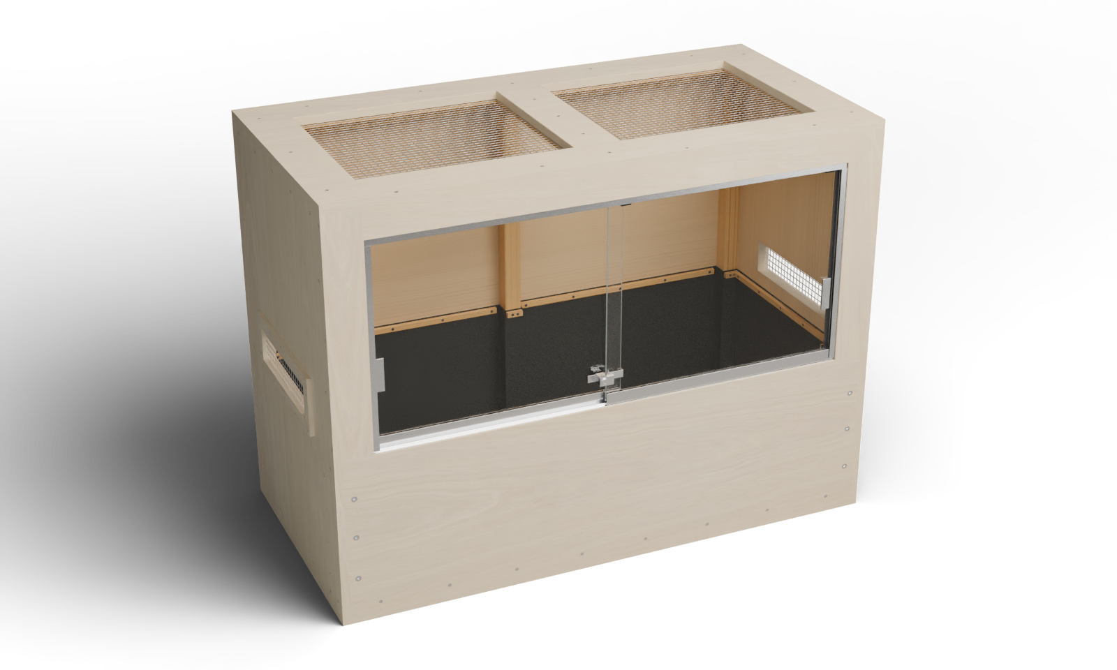
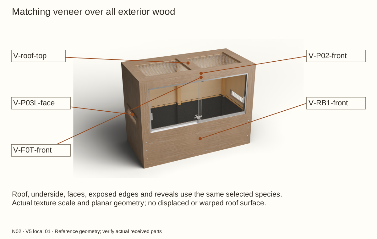
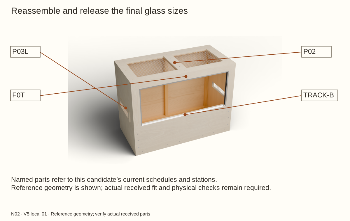
Full exterior veneer: the roof, faces, edges and reveals are included in this guide’s coordinated veneer schedule and geometry. Supplier balance, bond and actual-stack acceptance remain required. Natural grain and color vary.
About these previews
Rendered from this enclosure’s actual reference geometry. Veneer layers preserve service seams and bare hardware seats. The 3D viewer shows maple; these choices change the main picture. Texture scans by Jenelle van Heerden via Poly Haven, CC0 illustrate appearance and are not delivered veneer samples.
Two removable rolling glass doors, a separate one-piece lined bed and a removable screened roof. Follow 63 pictured operations with named parts, required waits and checks before continuing.
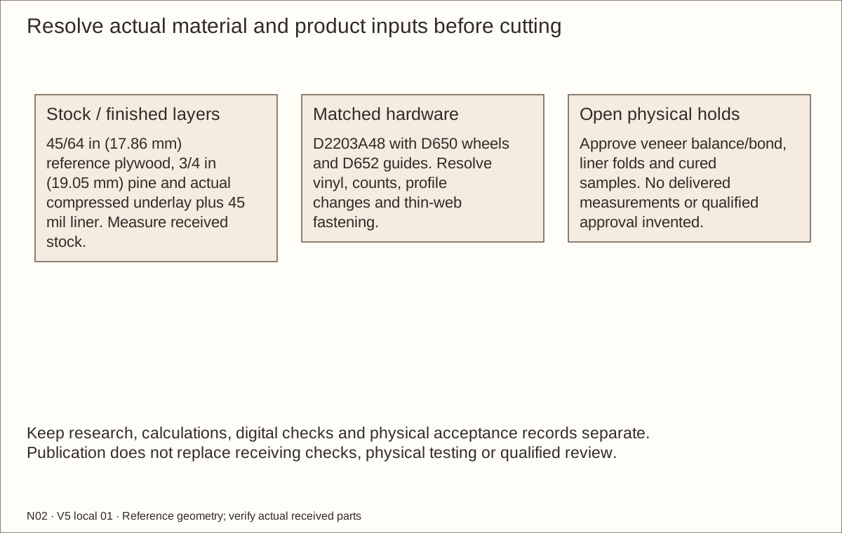
Construction holds: the six recessed retainer connections, received hardware, the disputed vinyl selection, modified jamb, veneer balance/bond, liner folds, prototype construction, physical testing and qualified review remain open.
This is the individual N02 lined design. Receive, measure and trial the exact materials before dependent final cuts. A changed plywood gauge, compressed lining, track profile or veneer system requires coordinated recalculation.
Measurement
Reference
Bare case
48 × 24 × 36 in (1219.2 × 609.6 × 914.4 mm)
Reference covered wood
48.061 in (1220.75 mm) × 24.061 in (611.15 mm) × 36.061 in (915.95 mm)
Maximum covered wood
48.092 in (1221.54 mm) × 24.092 in (611.94 mm) × 36.092 in (916.74 mm)
External capture width
48.811 in (1239.8 mm) at reference veneer; allow separate hardware/service space
Finished floor / bed
Floor 53/64 in (21.03 mm) above underside; maximum total bed 12 in (304.8 mm)
Clear rectangle above bed
43 11/32 in (1100.93 mm) × 17 15/16 in (455.61 mm) × 20 31/32 in (532.61 mm); equipment/furnishings reduce this
Bare door opening
41 19/32 in (1056.48 mm) × 17 31/32 in (456.41 mm)
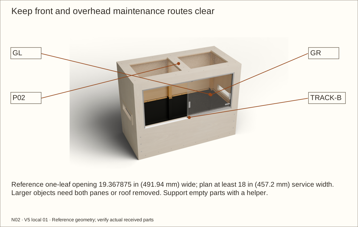
Reference one-leaf access
19.367875 in (491.94 mm) × 17.16375 in (435.96 mm); plan at least 18 in (457.2 mm) service width
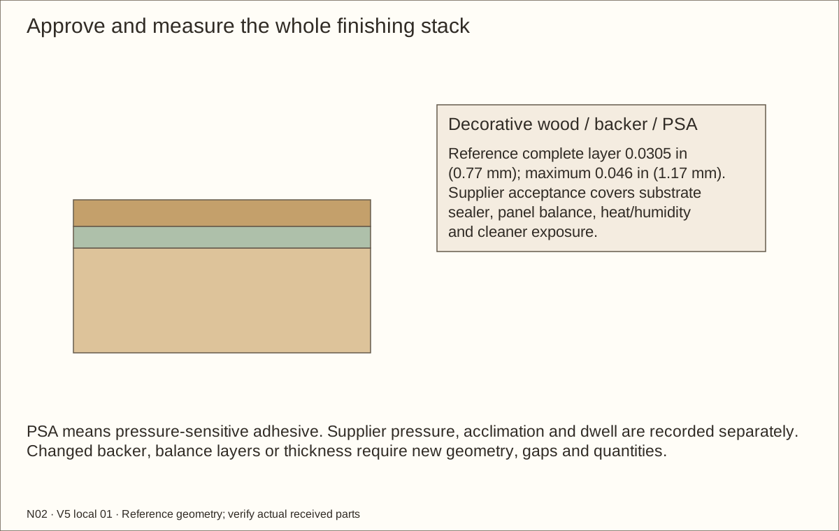
Complete veneer layer
Reference 0.0305 in (0.77 mm); maximum 0.046 in (1.17 mm)
Datums: assembly X starts at outside LEFT, Y at outside FRONT and Z at FLOOR UNDERSIDE, unless a local part edge is explicitly named. Exact mating decimals are retained. in means inches; mm means millimetres. The actual lining stack must be measured.
Tools, terms and safe workholding
Prepare a padded flat bench, helper, clamps, straight cauls, tape, square, marking knife, straightedge, caliper and drill depth stops. Use supported saw/router/jigsaw setups, sacrificial backing and safe wide carriers for narrow stock. Follow each tool maker’s guards and minimum feed lengths.
Use root-matched pilots, separate clearance bits, matching countersinks and fitting hand drivers. For each retainer connection, trial a 1-inch (25.4 mm) flat-bottom boring bit with a 5/8-inch (15.875 mm) depth stop, 9/32-inch (7.1438 mm) through bit, 82-degree countersink, 5/32-inch (3.9688 mm) hex key and 7/16-inch (11.1125 mm) socket no wider than 7/8 inch (22.225 mm). These are reference tools; prove the actual bit point, depth and socket fit on scrap first. Metal needs padded vise jaws, a suitable saw, files and supported drilling. Mesh needs snips and edge protection. Veneer needs a sharp knife, straightedge, sacrificial board and supplier-specified scraper. Glass comes fully fabricated; never cut/drill/grind it after tempering.
Wear eye/hearing protection, control dust and ventilate adhesives/coatings. Protect hands while handling sharp wire and metal; keep gloves and loose clothing away from rotating tools. Support both work and waste.
Term
Plain meaning
Cleat / lamination
Wood strip receiving screws / layers glued together
Jamb / header / retainer
Side of the opening / top frame member / front wall holding the bed
Ethylene propylene diene monomer rubber / one thousandth of an inch
Record the actual stock and floor datum
Plywood thickness: t = ______ in / ______ mm Compressed underlay + liner: a = ______ in / ______ mm Finished-floor elevation: F = t + a = ______
Part / elevation
Equation in inches
Reference
Floor / roof
48 × 24
48 × 24 in (1219.2 × 609.6 mm)
Side height
36 − 2t
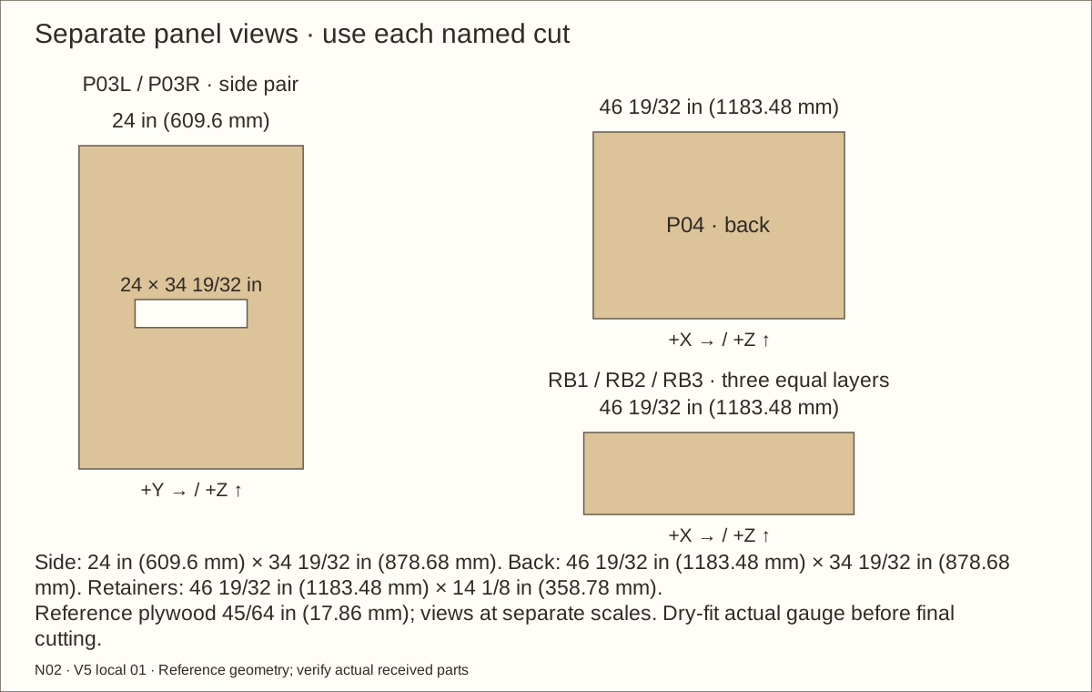
34 19/32 in (878.68 mm)
Back / retainer width
48 − 2t
46 19/32 in (1183.48 mm)
Retainer height above P01
14 + a
14 1/8 in (358.78 mm)
Door opening width
48 − 2t − 2 × 2.5
41 19/32 in (1056.48 mm)
Door opening height
36 − t − 2.5 − (F + 14)
17 31/32 in (456.41 mm)
Vent bottom from floor underside
F + 15
15 53/64 in (402.03 mm)
Maximum bed top
F + 12
12 53/64 in (325.83 mm)
Clamp screw centre
F + 13 3/8
14 13/64 in (360.76 mm)
Liner top
F + 13 3/4
14 37/64 in (370.28 mm)
These equations retain the core size and accepted nominal frame sections. They do not automatically revise every joint, screw, liner clamp or glass size. Recalculate the full coordinated candidate when a measured input changes. Use a marked measuring strip to transfer shared heights.
Tools / setup: Measuring tape, square, pencil and the tools named below
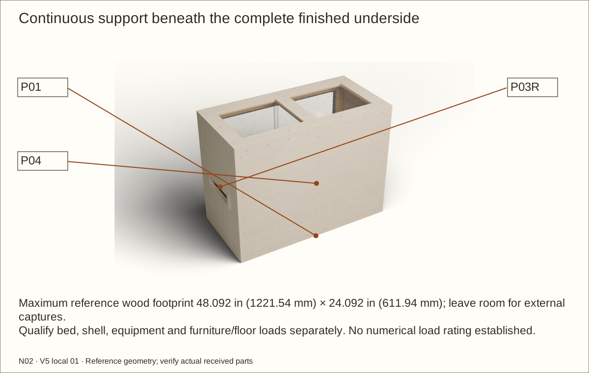
Qualify full support and the actual load
Choose a level, rigid, continuously supporting surface at least 48.092 in (1221.54 mm) wide × 24.092 in (611.94 mm) deep. It must support the complete veneered underside and every floor edge. Feet or two end rails do not satisfy this design.
The conservative bed-volume envelope is 6.74 cubic feet (191 L), before wood support displacement. At an assumed wet bulk density of 100 lb/ft³ (1602 kg/m³), the bed alone is 674 lb (306 kg). Weigh the actual wet mix; add the shell, water, furnishings and equipment when qualifying the furniture and floor.
Check before continuing: The full-footprint support and total-load review are recorded before assembly or loading.
Tools / setup: Measuring tape, square, pencil and the tools named below
Plan transport and maintenance access
Keep room above for complete roof/rib removal, in front for a helper supporting each pane, and beside both vents for airflow and cleaning. Allow the scheduled external capture width 48.811 in (1239.8 mm) plus working space. Rehearse the transport path while empty.
Do not stack enclosures, hang this box, climb on it or move it loaded. Plan separate furniture restraint to the actual wall structure if tipping is possible; this guide does not rate a stand or wall anchorage.
Check before continuing: The empty enclosure has a continuous support plan and a clear route for removing both glass leaves and the roof.
Parts: Actual product samples and supplier replies
Tools / setup: Measuring tape, square, pencil and the tools named below
Resolve the product and veneer holds
Read H01–H10 before dependent purchases or cuts. Obtain CRL acceptance for this matched D2203A48 closure, vinyl, uncapped shoes, modified right jamb, thin-web screws and removal/anti-lift design. Save the supplier response; rejected details need redesign.
Choose ONE exterior species: maple, white oak or walnut. The schedule needs three 48 in (1219.2 mm) × 96 in (2438.4 mm) sheets with the approved PSA backer. Confirm panel balance, cured coating compatibility, humidity/heat/cleaner exposure, acclimation, pressure and dwell. A changed backing or balancing layer needs new geometry and quantities.
Approve the exact liner/underlay application and coating/cushion-bond samples. No received product or physical trial has yet been supplied. The open holds distinguish this digital candidate from construction acceptance.
Check before continuing: Required written answers are recorded before proceeding; rejected or unresolved substitutions stay on hold.
Tools / setup: Measuring tape, square, pencil and the tools named below
Inventory wood and the nylon-wheel track kit
Measure the actual thickness of the nominal 3/4 in (19.05 mm) plywood at several points. Reject delaminated sheets and warped stock. Check solid wood supports are 1 1/2 in (38.1 mm) square and the frame pine is 3/4 in (19.05 mm) thick.
Receive the complete CRL D2203A48 kit, separately selected glazing vinyl, separate 144 in (3657.6 mm) D603A jamb stock, 963L lock and FP86 pulls. The precut kit uses four D650 nylon wheels and four D652 guides. Confirm actual inventory and the usable length of both overlapping shoe blanks. Cosmetic caps are omitted subject to accepted wheel retention and smooth uncapped ends.
Check before continuing: Received wood gauges and matched D2203A48 kit contents are recorded; no glass has been ordered.
Tools / setup: Measuring tape, square, pencil and the tools named below
Measure the lining and transfer height marks
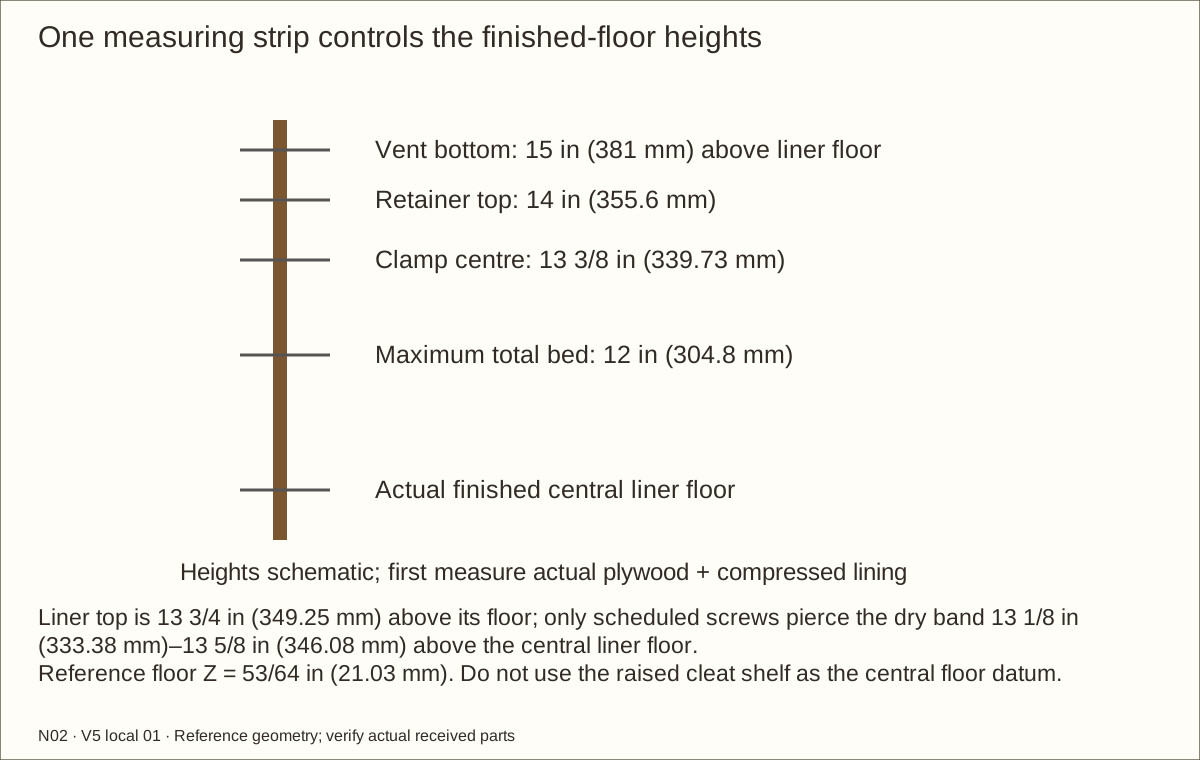
Place the underlay and 45 mil (0.045 in / 1.14 mm) EPDM liner together on a smooth offcut. Measure the actual compressed stack without a corner fold. The reference is 0.08 in (2.03 mm) underlay plus 0.045 in (1.14 mm) liner, totaling 1/8 in (3.18 mm). These separate values are planning allowances, not measured delivery. Record the actual result on a marked measuring strip.
On the measuring strip, mark the floor underside. Above it, mark the actual plywood thickness plus compressed lining to locate the finished floor. From that mark, measure up 12 in (304.8 mm) for the maximum total bed, 14 in (355.6 mm) for the retaining-panel top and 15 in (381 mm) for the vent bottom. Transfer these marks to the build.
Check before continuing: The actual compressed lining and all shared height marks are recorded on the measuring strip.
Tools / setup: Measuring tape, square, pencil and the tools named below
Cut this build’s plywood blanks
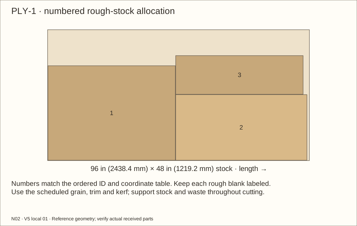
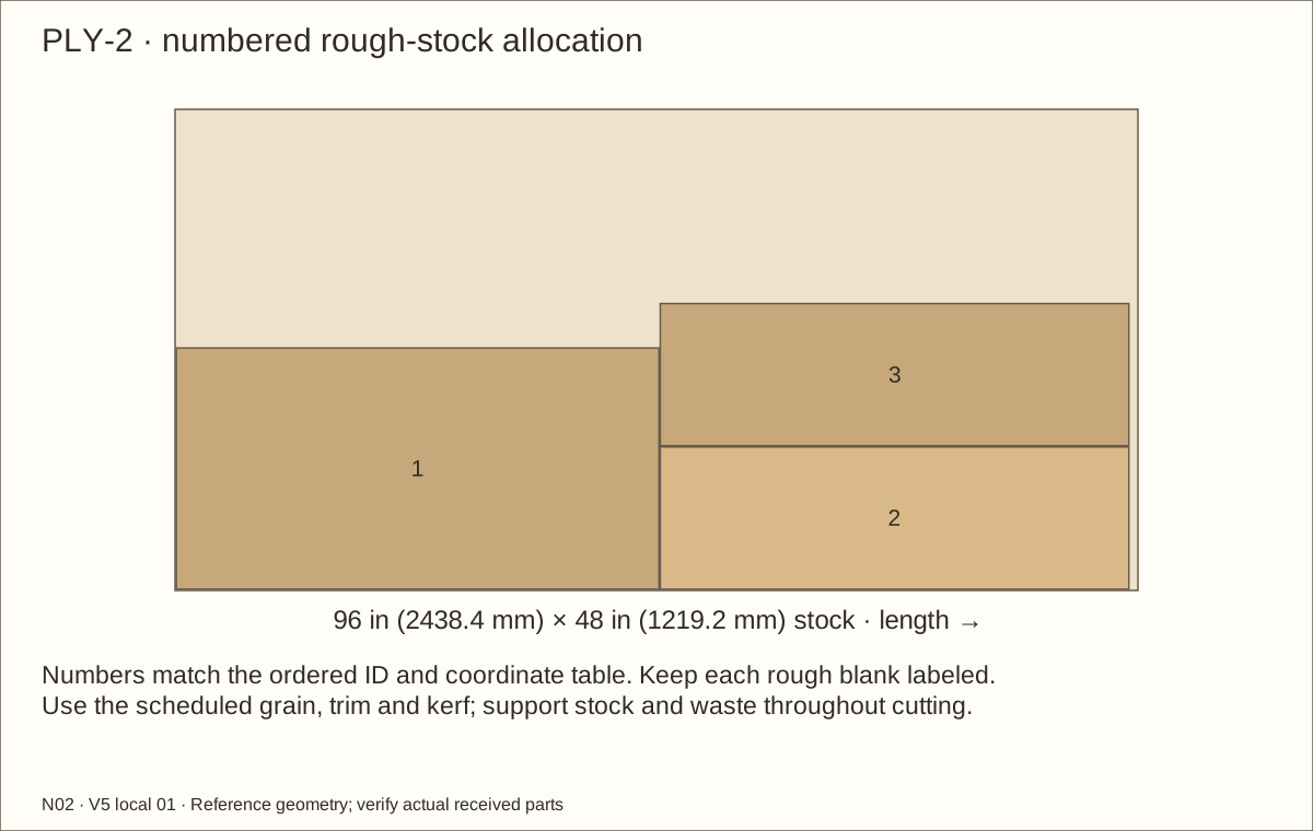
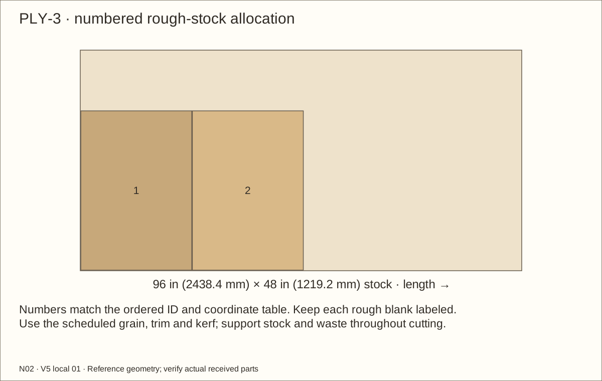
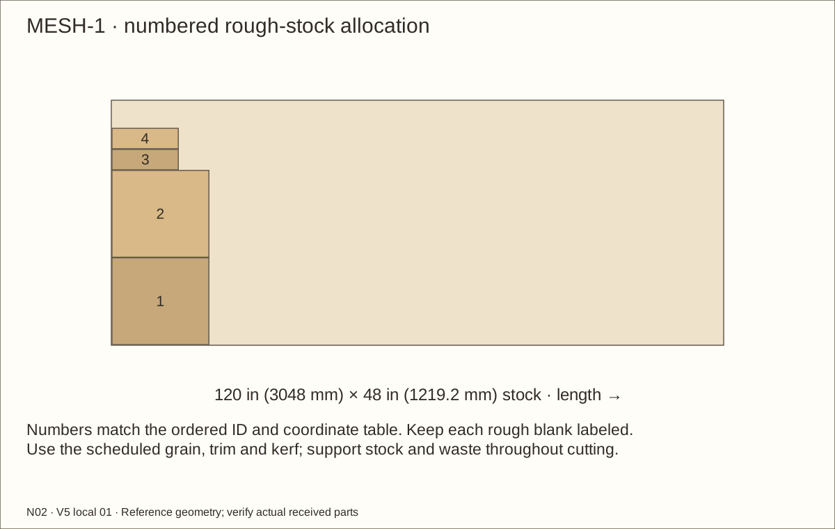
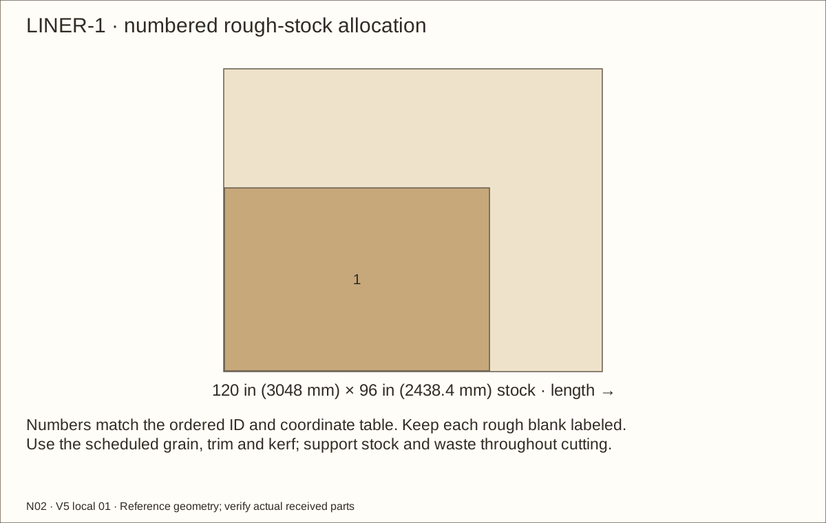
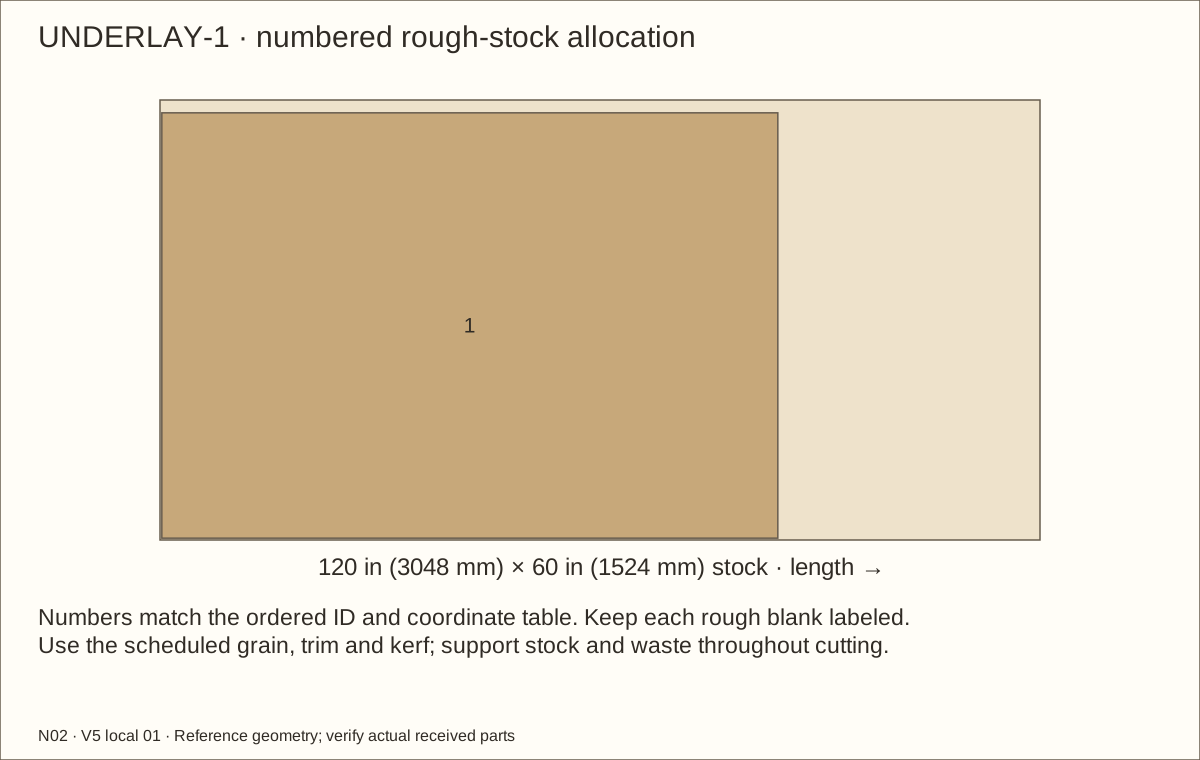
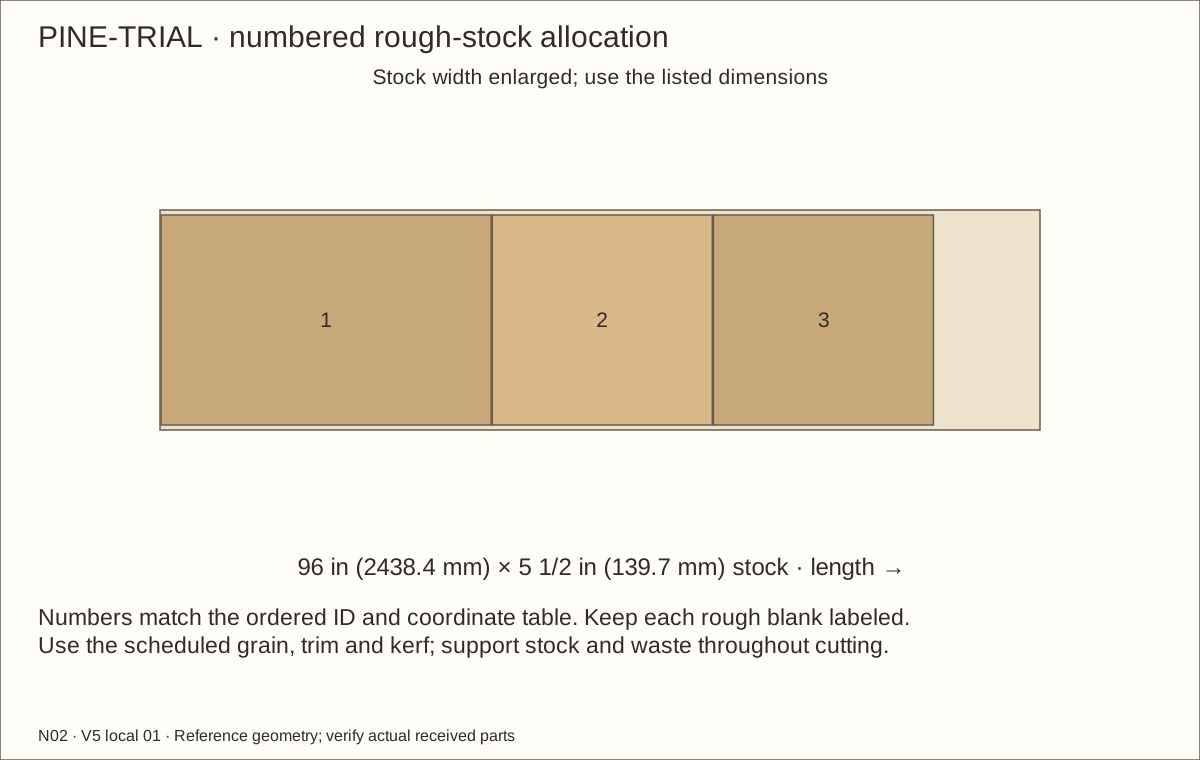
Use all three PLY layouts and matching exact stock tables. Square a reference edge, support both cut sides and allow the scheduled 1/8 in (3.18 mm) kerf. Start with labeled rough blanks; floor and roof finish at 48 in (1219.2 mm) × 24 in (609.6 mm). Keep their grain along the 48 in (1219.2 mm) dimension and the long back/retainer span. This trim-tolerant layout uses three sheets; it does not depend on a perfect factory 48 in (1219.2 mm) edge.
For the 45/64 in (17.86 mm) reference plywood, side panels finish at 24 in (609.6 mm) × 34 19/32 in (878.68 mm); the back at 46 19/32 in (1183.48 mm) × 34 19/32 in (878.68 mm); and all three retainer layers at 46 19/32 in (1183.48 mm) × 14 1/8 in (358.78 mm). Fit sides between floor and roof within the 36 in (914.4 mm) core height, and back/retainer between sides. A changed received gauge requires coordinated recalculation before final cutting.
Check before continuing: Opposite sides match; all three retainer boards have the same height and square edges.
Tools / setup: Measuring tape, square, pencil and the tools named below
Label, pair and fit the plywood
Mark every part ID, front edge, inside face and grain direction in pencil. Keep the long grain across the back and retainer span. Stack matching parts and check them with a straightedge; correct discrepancies before holes.
Use one imperial measuring system and a shared marked strip. Metric values are equivalents. Exact mating decimals in the workshop tables are intentional. Mark the final line from the actual mating pieces, leave it during the rough cut, then fit matching pairs together.
Check before continuing: Opposite sides match; all three retainer boards have the same height and square edges.
Tools / setup: Measuring tape, square, pencil and the tools named below
Mark the two roof openings
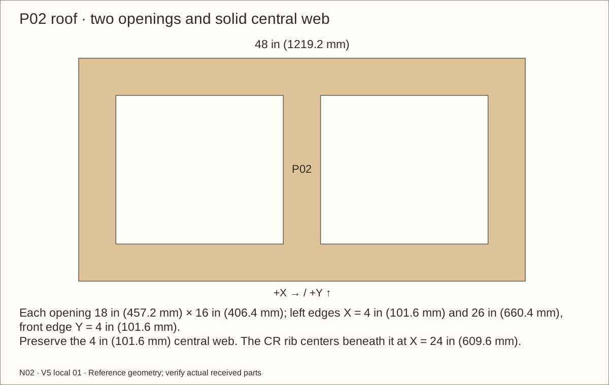
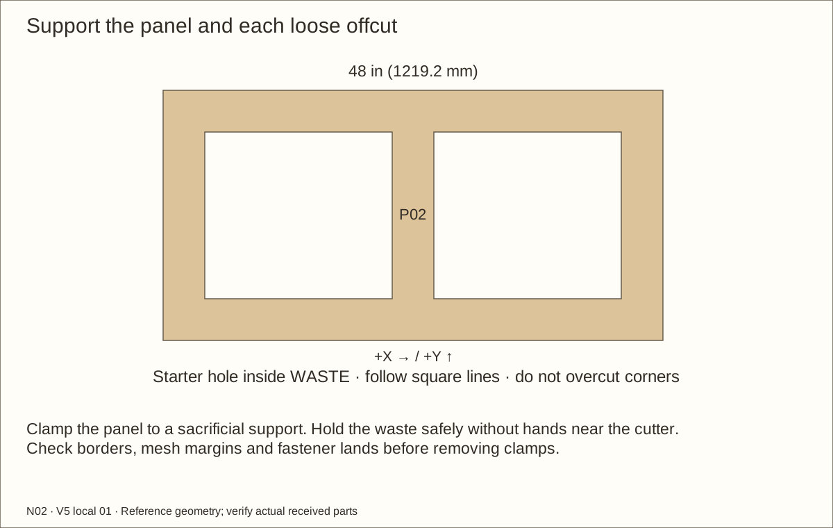
On the roof, mark two 18 in (457.2 mm) × 16 in (406.4 mm) openings. Their front edges are 4 in (101.6 mm) from the front; left edges are 4 in (101.6 mm) and 26 in (660.4 mm) from the left. Keep the centre strip intact.
Check before continuing: Both roof-opening outlines have the scheduled borders and intact centre strip.
Tools / setup: Measuring tape, square, pencil and the tools named below
Mark both raised wall vents
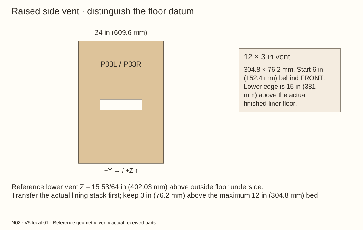
On each side, mark a 12 in (304.8 mm) × 3 in (76.2 mm) opening starting 6 in (152.4 mm) behind the front edge. Its lower edge is 15 in (381 mm) above the finished-floor mark, not the floor underside.
Check before continuing: Both side-vent outlines start 3 in (76.2 mm) above the maximum bed line measured from the actual finished floor.
Parts: P02 — Removable roof; P03L — L wall; P03R — R wall
Tools / setup: Measuring tape, square, pencil and the tools named below
Cut supported openings and check borders
Drill starter holes entirely inside the waste. Cut with a guided router or supported jigsaw; do not cross the marked corner lines. Ease sharp reveals and remove every splinter.
Mark the scheduled capture-strip footprints over the opening margins, using full-size paper templates while the strips are still uncut. Each mesh edge must fit beneath a strip, and no fastener station may land in an opening. Leave the rest of the roof solid; equipment penetrations are a later, separately fitted operation.
Check before continuing: Both vents start 3 in (76.2 mm) above the maximum total bed; all roof borders and the centre strip remain intact.
Tools / setup: Measuring tape, square, pencil and the tools named below
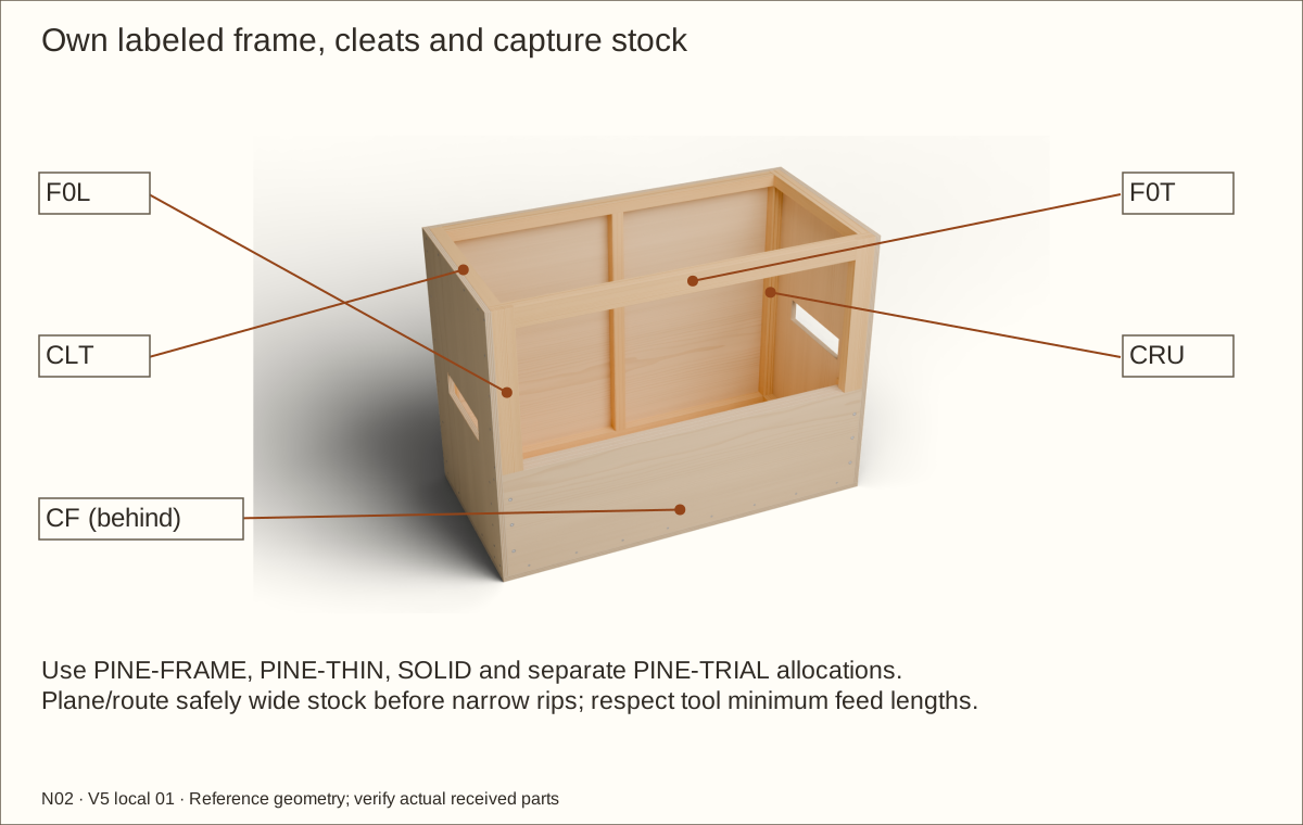
Prepare safe wide frame and strip stock
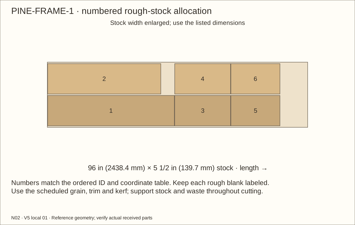
Use the labeled PINE-FRAME layouts, not a guessed board number. Rip the 2 1/2 in (63.5 mm) frame strips with guards, featherboards and push sticks; crosscut the named jamb/header layers. Reserve the separate trial board for hardware, screen and finish samples.
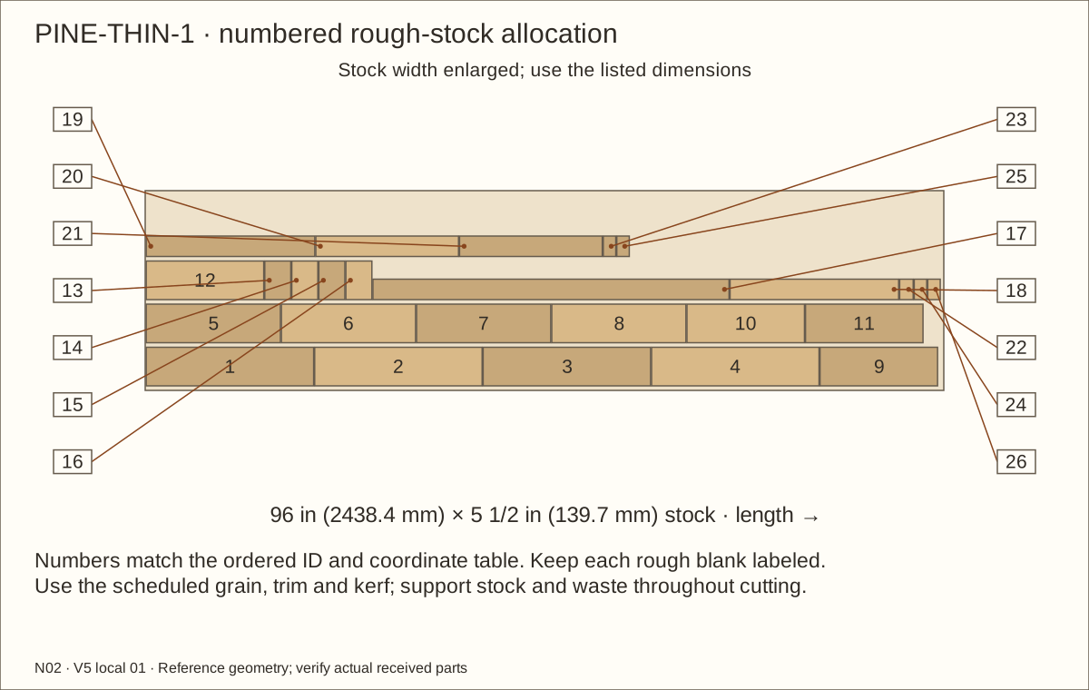
Prepare safe full-width PINE-THIN stock to 3/8 in (9.53 mm) thickness before ripping the new 1 in (25.4 mm) screen captures and 1/2 in (12.7 mm) liner clamps. Route screen recesses while blanks are wide and supported. Follow machine minimum feed lengths; never thickness or route a loose narrow strip by hand near a cutter.
Check before continuing: Frame and strip stock is identified, sound and safely prepared for the next cuts.
Tools / setup: Measuring tape, square, pencil and the tools named below
Cut and dress the solid supports
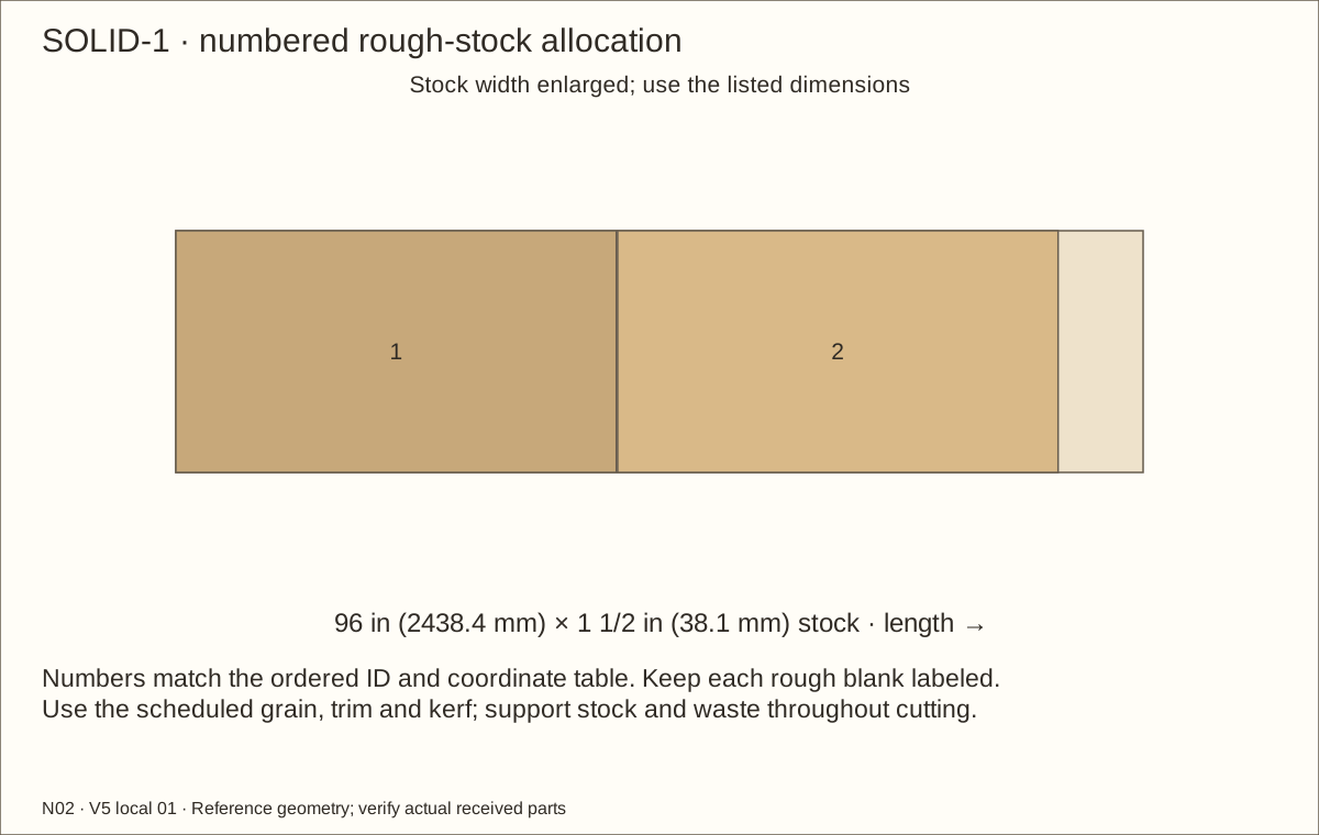
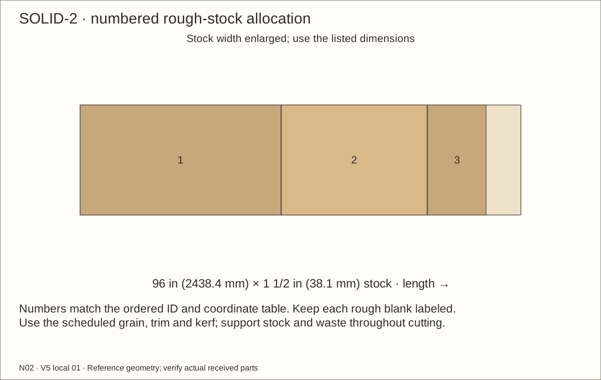
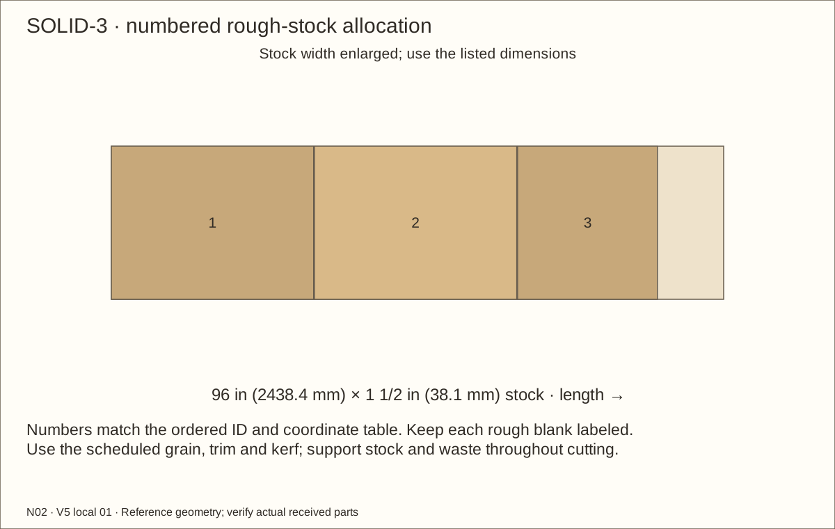
Use the five labeled SOLID-stock layouts for the four bottom cleats, three rear uprights, two front posts, three upper supports and one roof rib. The nominal 2-by-2 lumber designation means a reference section of 1 1/2 in (38.1 mm) square. Measure the full received section; these are solid supports, not laminated strips.
Lightly ease exposed corners and especially the wood supports beneath the liner. Keep joint faces square and bare. Label the underside of each roof capture so it returns to its own holes.
Check before continuing: Each solid member and thin strip is identified; no cracked or knot-weakened wood support is used.
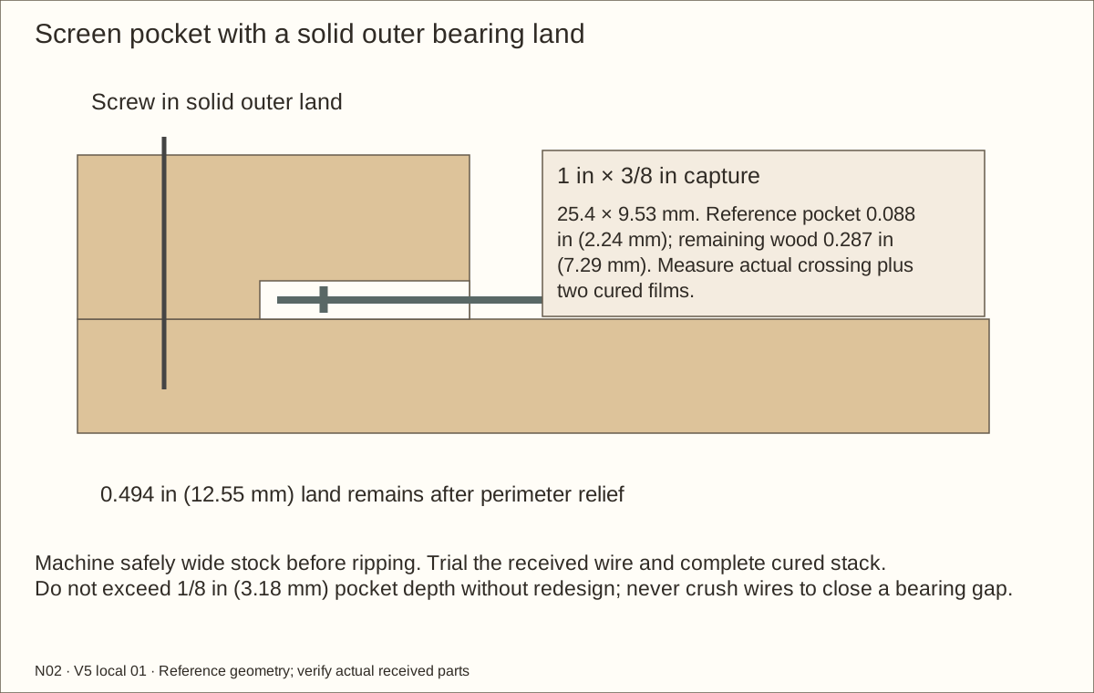
Measure the largest welded-wire crossing and the actual cured film on both bearing faces. Reference wire is 0.041 in (1.04 mm), crossing 0.082 in (2.08 mm), and two 0.003 in (0.08 mm) films give a 0.088 in (2.24 mm) pocket. These are model inputs, not delivered tolerances.
On a wide clamped trial blank, use a guided router and shallow passes to form the rebate: a shallow edge pocket. Leave a full outer bearing land. The nominal 1/2 in (12.7 mm) land loses 0.006 in (0.15 mm) to perimeter fitting relief, leaving 0.494 in (12.55 mm). It must sit flat while all wire ends remain buried.
Do not exceed 1/8 in (3.18 mm) pocket depth without redesign. Trial with the received mesh and finish, then machine safely wide blanks before final ripping/crosscutting. Record depths and labels on all sixteen capture strips.
Check before continuing: Pocket fits the actual crossing; lands sit flat and wire cannot peel or rattle.
14. Laminate the retainer and staggered front frame
Parts: RB1, RB2, RB3, F0L, F0R, F0T, F1L, F1R, F1T; use labeled picture and schedules
Tools / setup: Measuring tape, square, pencil and the tools named below
Laminate the retainer and staggered front frame
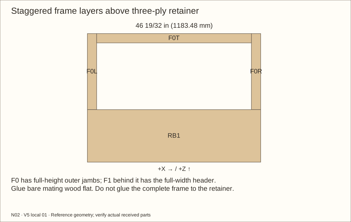
Dry-stack RB1, RB2 and RB3 face to face, flush at their top and ends. Their combined depth matches three layers of the actual plywood. Dry-lay the front frame above them: outer layer jambs run full height, inner layer header runs full width.
Spread Titebond III on the two retainer bond interfaces and between the two frame layers. Keep a consistent film across bare wood; use padded straight clamping pads and enough clamps to close the joints without bowing the long members.
Compare both frame diagonals and check the track-bearing faces with a straightedge. Wipe away squeeze-out before it hardens. Do not glue the frame to the retainer; these remain separate assemblies for finishing and removal.
Follow the glue label for temperature and clamping. Leave these unstressed glue-ups for at least 24 hours before drilling or loading, extending the wait when the manufacturer requires it.
Check before continuing: The laminated retainer is flat and the 1 1/2 in (38.1 mm) deep frame has staggered, closed joints.
Required wait: Glue cure: at least 24 hours; follow the received label
Tools / setup: Measuring tape, square, pencil and the tools named below
Trial the received track and glass system
Make a rigid gauge matching the actual square dry frame. The reference clear opening is 41 19/32 in (1056.48 mm) × 17 31/32 in (456.41 mm). Use a smooth disposable 6 mm thickness sample for initial fit; it is not a substitute door. Final approval includes a fabricator-provided glass sample of the accepted thickness.
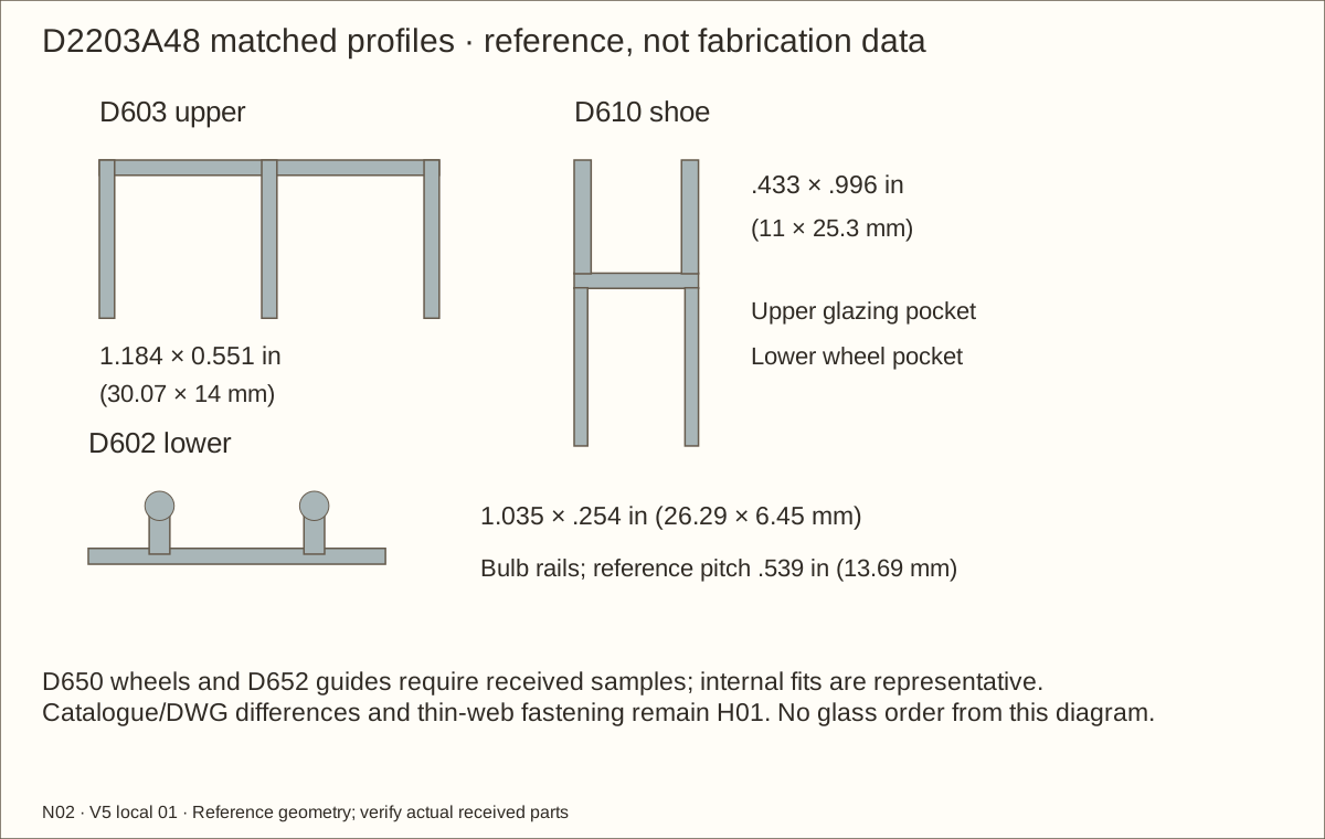
Seat the sample in a D610 offcut with supplier-confirmed vinyl. Fit a D650 wheel assembly and a D652 guide according to the received instructions. Compare the D602 bulb rail, D603 upper channel and guide engagement with the catalogue/DWG reference; resolve discrepancies before final cuts.
Check the nominal 1 1/8 in (28.58 mm) glass-height deduction with the complete received assembly. Trial uncapped, fully deburred shoe ends, wheel retention, closing cushions, right-jamb divider relief and sufficient removal lift. Do not cut a supplier-rejected profile or force a tight glazing channel.
Check before continuing: The sample rolls, lifts out with retention removed, and seats securely with the guide inside the upper channel.
Tools / setup: Measuring tape, square, pencil and the tools named below
Trial uncut liner folds around a post
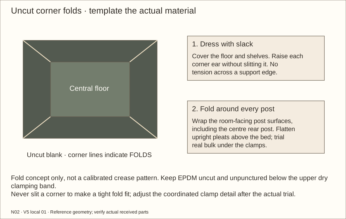
Fold actual liner and underlay offcuts over a dressed cleat and around representative front and rear post corners. Keep the central floor mark distinct from the raised shelf. Test uncut corner pleats and the clamp grip. The nominal 1/8 in (3.18 mm) wall allowance may not accommodate folded bulk; change clamp offsets and all dependent checks before proceeding if the real stack requires more space.
Check before continuing: Actual folded stack fits without a stretched membrane, sharp contact or unsupported clamp.
Parts: P01 — Floor; CLB — L bottom cleat; CRB — R bottom cleat; CF — Front floor cleat; CB — Back floor cleat
Tools / setup: Measuring tape, square, pencil and the tools named below
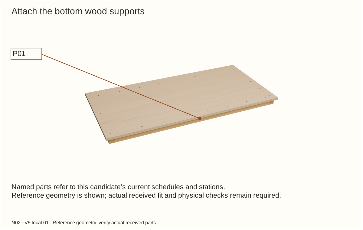
Position and drill the bottom cleats
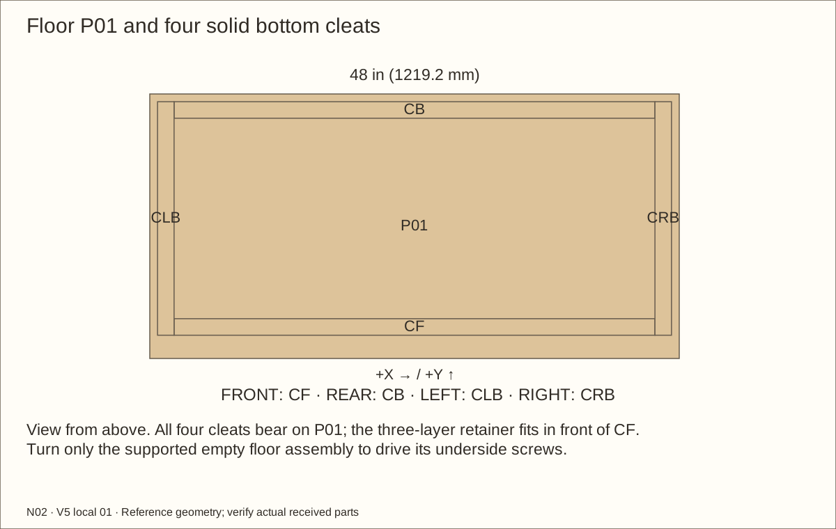
Place P01 on a flat sacrificial board. Set the left and right bottom supports inward by the actual side-panel thickness, using an offcut as a spacer. Set their front ends behind the three-layer retaining panel. Fit CF between them against the back of that panel; fit CB between them against the inside face of the back panel.
Clamp each wood support. Transfer the bottom-support stations through the floor: #8 clearance holes are 11/64 in (4.37 mm) through P01 only; start 7/64 in (2.78 mm) pilots into pine and confirm grip on an offcut. Set a stop so no drill or screw can emerge.
Check before continuing: Cleats are clamped in their scheduled positions; front and rear panel recesses fit; pilot and clearance paths remain within their receivers.
Parts: P01 — Floor; CLB — L bottom cleat; CRB — R bottom cleat; CF — Front floor cleat; CB — Back floor cleat
Tools / setup: Measuring tape, square, pencil and the tools named below
Glue and fasten the floor from underneath
Apply Titebond III only to the floor/wood support bond faces. Drive the #8 × 1 1/4 in (31.75 mm) screws from below, leaving their heads flush with the floor underside. Wipe all squeeze-out and keep the four corner beds smooth.
Check the retainer and back-panel recesses before the glue sets. Let the floor assembly remain flat and unstressed during cure.
Check before continuing: The floor underside sits completely flat, with no projecting head; the front recess fits the three-layer retaining panel.
Required wait: Do not stress glued wood supports for at least 24 hours
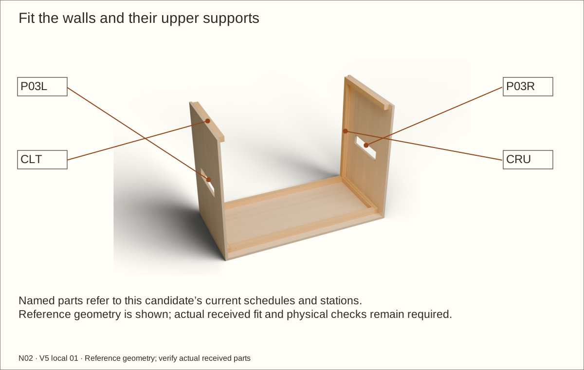
Parts: P03L — L wall; P03R — R wall; CLU — L rear upright; CRU — R rear upright; CLT — L upper cleat; CRT — R upper cleat
Tools / setup: Measuring tape, square, pencil and the tools named below
Fit the two walls and upper supports
Clamp CLU and CLT to the inside of the left wall; repeat with CRU and CRT on the right. Upper wood supports end at the back-panel face and start 1 1/2 in (38.1 mm) behind the front. The rear uprights fit between lower and upper wood supports.
Stand each wall on P01, flush with its outer edge and front. Clamp it to the bottom wood support. Use a helper while the box is open.
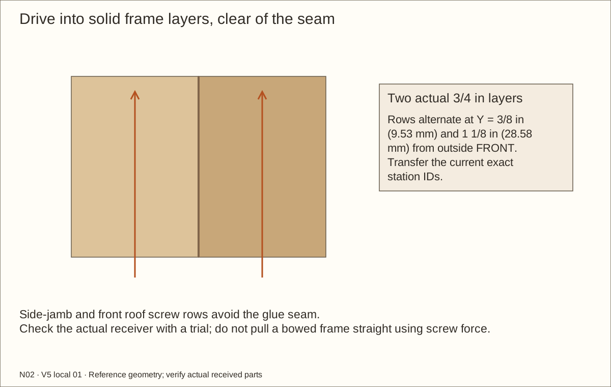
Transfer the listed stations through each wall into the matching solid receiver. Drill the #8 clearance through the plywood, then a stopped pilot into pine. Keep the rear-upright back screws offset from the side screws as shown in the station schedule.
Fasten with #8 × 1 1/4 in (31.75 mm) screws, tightening by hand for the last turn. These wall joints stay dry during fitting so the panels can be removed for finishing.
Check before continuing: Walls are upright and parallel; all screw points terminate in solid wood supports, and no screw projects into the room.
Tools / setup: Measuring tape, square, pencil and the tools named below
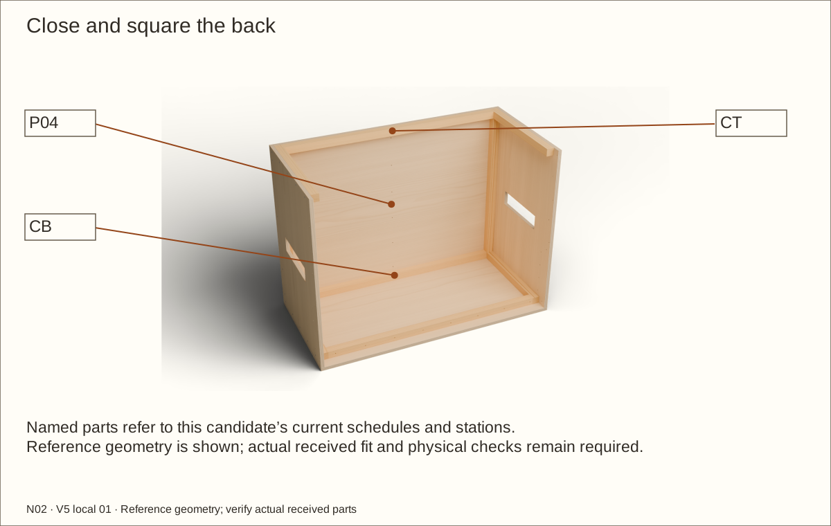
Close and square the back
Fit P04 between the side panels, resting on the floor with its outside face flush to the side-panel rear edges. Clamp to CB, CT and both rear uprights.
Compare the two diagonals across the front and across the back. Adjust until each pair differs by no more than 1/16 in (1.59 mm). Recheck on the final supporting surface if it differs from the bench.
Drill clearance through P04 and stopped pilots into the named receivers at the close and square the back operation stations. Use the offset upright positions so a back screw does not meet a side screw.
Fit the #8 × 1 1/4 in (31.75 mm) screws and check that the full back edge sits flush. Do not pull a twisted box square by overdriving a screw.
Check before continuing: The shell remains square without clamp pressure; the back and both walls bear on the floor.
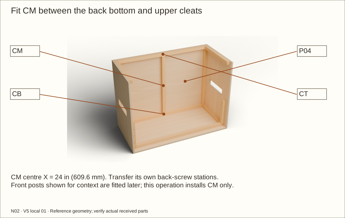
Parts: CM — centre rear upright; P04 — back; CB / CT — lower and upper rear cleats
Tools / setup: Measuring tape, square, pencil and the tools named below
Fit the centre rear upright
Fit CM centrally against P04 at X = 24 in (609.6 mm), between the lower rear cleat CB and upper support CT. Its reference length is 31 19/32 in (802.48 mm). Keep the ends square and in full bearing.
Clamp CM square without bowing P04. Transfer its six rear-facing stations using the matching drawing and exact table. Drill clearance through P04 and stopped pilots into CM.
Fit six #8 × 1 1/4 in (31.75 mm) screws flush from the back. Keep the entire screw point buried; check the reference pilot and countersink in matching offcuts first.
Recheck the back diagonals and support bearing. Ease the liner-facing corners while preserving the full load-bearing section. The two front posts are fitted in the following pictured operations.
Check before continuing: CM is square, in full end bearing and fixed by six buried-point rear screws; the back stays square.
Tools / setup: Measuring tape, square, pencil and the tools named below
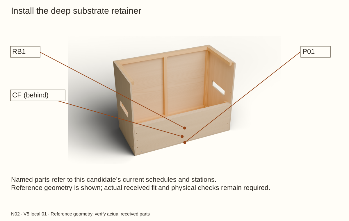
Seat the three-layer retaining front
Seat the cured three-layer retainer on P01 in front of CF. Its ends fit between the side panels and its front face is flush with the front of the floor.
Set the wood retaining-panel top 14 in (355.6 mm) above the finished floor, before adding the track. A 12 in (304.8 mm) total bed leaves 2 in (50.8 mm) to the wood top.
Check before continuing: The retaining top is level at the marked height and the cured laminate bears fully on the floor.
Tools / setup: Measuring tape, square, pencil and the tools named below
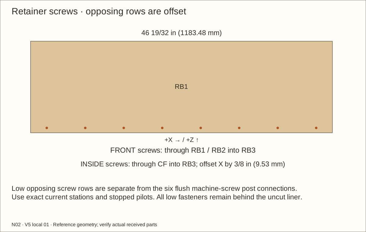
Fasten the retainer with offset screw rows
At the end stations, drill #8 clearance through each side and pilots into the retainer ends. At the front stations, drill clearance through RB1 and RB2 and pilots into RB3; keep the 2 in (50.8 mm) screws within the laminate.
From inside, drill clearance through CF and pilots into RB3 for the separate rear-facing 2 in (50.8 mm) screws. Offset these stations 3/8 in (9.53 mm) to the right of the front-facing stations so opposing screws cannot meet. Tighten all screws flush; these low fasteners will be isolated behind the uncut liner.
Check before continuing: The retaining top is level, continuous and at the marked reference mark; no screw point projects through its inner face.
Parts: CFL / CFR — front posts; CLB / CRB — bottom side cleats; RB3 — inner retainer layer
Tools / setup: Measuring tape, square, pencil and the tools named below
Before you begin: Bolt and hardware dimensions are receiving checks; never infer structural capacity from bolt count.
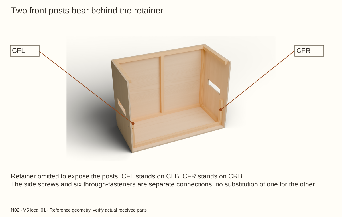
Position and secure both front posts
Stand CFL and CFR behind the retainer, bearing on CLB and CRB respectively. Their reference length is 12 5/8 in (320.68 mm). Clamp each square with its front face against RB3 and top flush with the retainer.
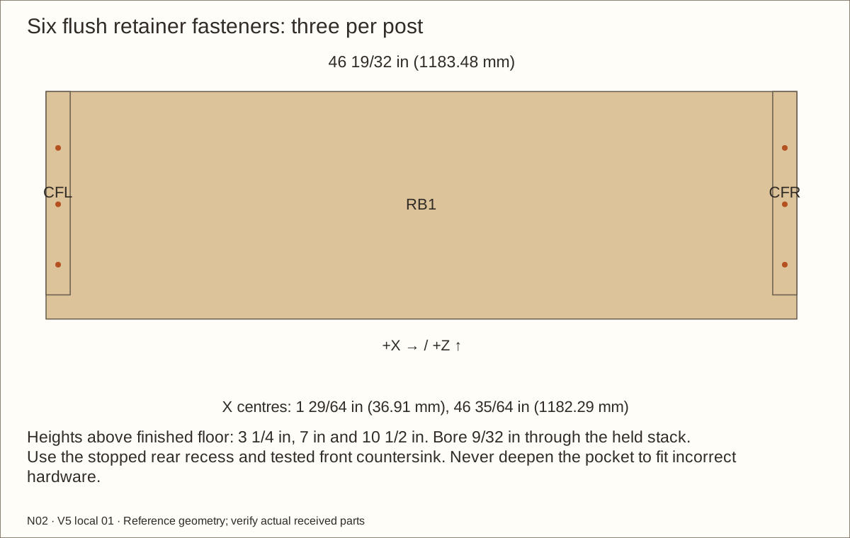
Fit four side screws per post at 2 1/2 in (63.5 mm), 5 1/2 in (139.7 mm), 8 1/2 in (215.9 mm) and 11 1/2 in (292.1 mm) above the finished floor, using clearance through each side and stopped pilots into its clamped post. Keep both posts square and bearing on their lower cleats.
Check before continuing: Both posts bear on their named cleats and are square, with four side screws each and six through-connections still to fit.
Tools / setup: Measuring tape, square, pencil and the tools named below
Before you begin: Bolt and hardware dimensions are receiving checks; never infer structural capacity from bolt count.
Trial the flush retainer connection and nut recess
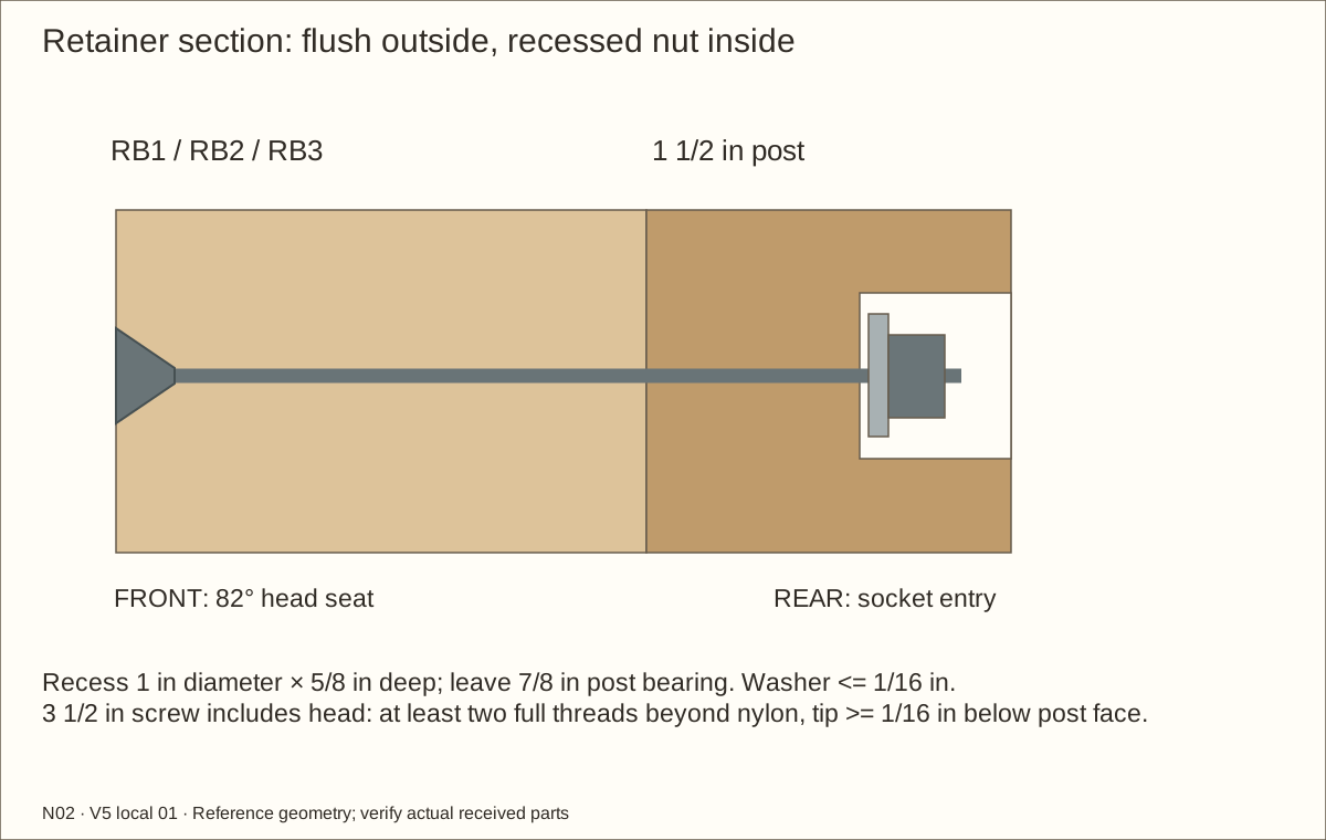
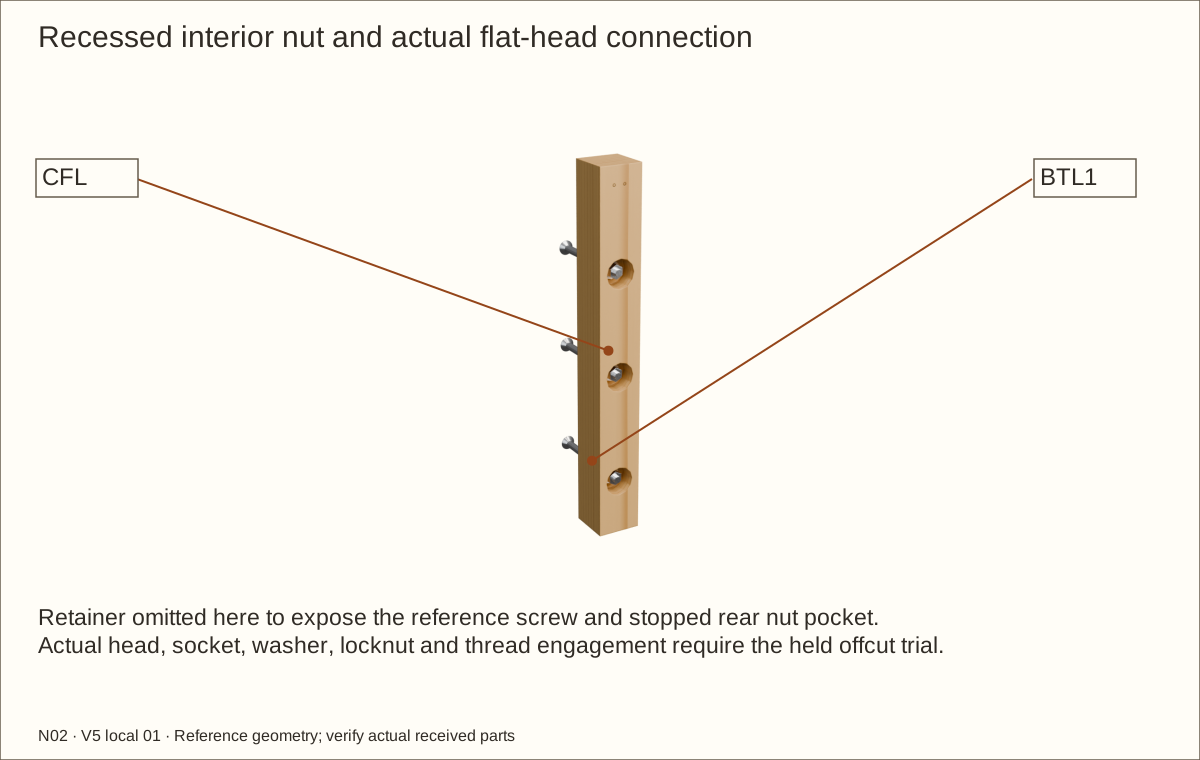
Before touching a finished part, trial the exact Bolt Depot 24910 1/4-20 × 3 1/2 in (88.9 mm) flat-head screw, 16019 washer and 16008 nylon locknut in matching offcuts. Length includes the head. Use a 5/32 in (3.97 mm) hex driver and the received nut’s 7/16 in (11.11 mm) wrench. Hand-tighten slowly; stainless can seize, so stop rather than force binding threads.
Reference rear recess is 1 in (25.4 mm) diameter and 5/8 in (15.88 mm) deep, leaving 7/8 in (22.23 mm) of the 1 1/2 in (38.1 mm) post at its washer seat. Hold the loose post square under a stopped flat-bottom bit with backing and clamps. Confirm the actual socket outside diameter is no more than 7/8 in (22.23 mm) and can enter with clearance. Do not deepen the recess to make a wrong bolt fit.
Check before continuing: Actual hardware and held sample satisfy socket, wood-bearing, thread and tip-clearance limits.
Tools / setup: Measuring tape, square, pencil and the tools named below
Before you begin: Bolt and hardware dimensions are receiving checks; never infer structural capacity from bolt count.
Bore and fit all six flush retainer screws
Mark three centres per post at 3 1/4 in (82.55 mm), 7 in (177.8 mm) and 10 1/2 in (266.7 mm) above the finished floor. Their X coordinates are 1 29/64 in (36.91 mm) and 46 35/64 in (1182.29 mm) from outside left. These revised centres avoid N02’s own four side screw paths. Clamp the stack and drill 9/32 in (7.14 mm) clearance square through RB1/RB2/RB3 and the post. Use the tested 82-degree front countersink only deep enough for the flat head to sit flush.
Insert the screw from outside. Inside its rear post recess, install one washer and the complete nylon locknut. Received washer must be at most 1/16 in (1.59 mm) thick for this reference stack. Require at least two full threads beyond the nylon and at least 1/16 in (1.59 mm) tip clearance below the post face. Tighten only to close the joint; do not crush wood or assign a torque from this drawing.
Check before continuing: Six joints close flat, threads fully engage and all tails remain safely recessed.
Tools / setup: Measuring tape, square, pencil and the tools named below
Before you begin: Bolt and hardware dimensions are receiving checks; never infer structural capacity from bolt count.
Inspect and protect the recessed hardware
Check the post is flat, remaining wood intact and no metal edge can catch the liner. Keep a 0.55 in (13.97 mm) veneer service opening around each exterior flat head. Finish and fully cure the recess before reassembly; place supplementary loose underlay pads over the recessed hardware. No fastener pierces the membrane. Connection capacity and actual sample acceptance remain open holds.
Check before continuing: Reference bearing remains intact; surfaces are smooth and the accepted padding arrangement can be fitted.
Parts: F0L — L jamb layer; F0R — R jamb layer; F0T — Header layer; F1L — L jamb layer; F1R — R jamb layer; F1T — Header layer
Tools / setup: Measuring tape, square, pencil and the tools named below
Fit the laminated jambs and header
Set the laminated front frame on the retaining top. Align its front face with the retainer and sides. Both jambs must bear fully on the retainer; do not suspend them on screws.
Clamp the frame square. Drill #8 clearance through the side panels into stopped pilots in the jamb ends at the scheduled heights. Fit #8 × 2 in (50.8 mm) screws.
Measure the clear opening at the top, middle and bottom and its clear height at three positions. The reference width is 41 19/32 in (1056.48 mm) and height 17 31/32 in (456.41 mm). Record the smallest values and both diagonals.
Lay a straightedge beneath the header and over the retainer. Correct any bow now. The detachable roof will later screw into the header and wood supports, further closing the box.
Check before continuing: The opening is square within 1/16 in (1.59 mm) and its upper/lower track faces are straight and parallel.
29. Check receivers, stopped pilots and flush heads
Parts: Named parts shown in the picture
Tools / setup: Measuring tape, square, pencil and the tools named below
Check receivers, stopped pilots and flush heads
Compare the assembled shell with the part list and inspect every joint from both sides. Use the fastener-stations download to check that no receiver, through-member or screw is missing.
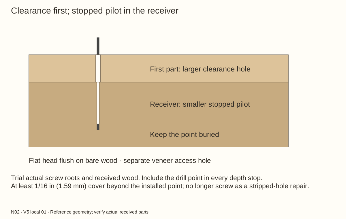
Make pilot tests in matching offcuts. The starting pilots are 7/64 in (2.78 mm) for #8, 3/32 in (2.38 mm) for #6 and 1/16 in (1.59 mm) for #4. Adjust for the actual wood and screw root; a split or spinning test means the setup is wrong.
Set the clearance depth separately from the receiver pilot. Use 11/64 in (4.37 mm), 9/64 in (3.57 mm) and 1/8 in (3.18 mm) starting clearance bits for #8, #6 and #4 respectively. Confirm head shape in a scrap countersink.
Keep at least 1/16 in (1.59 mm) undrilled wood beyond a screw point. Do not substitute a longer screw to repair a stripped hole; repair or replace its receiver and repeat the trial.
Check before continuing: No point, burr, split, hollow screw path or proud floor screw remains.
Parts: ML — L ventilation mesh; MR — R ventilation mesh; MTL — Roof mesh; MTR — Roof mesh
Tools / setup: Measuring tape, square, pencil and the tools named below
Cut, deburr and label the four mesh pieces
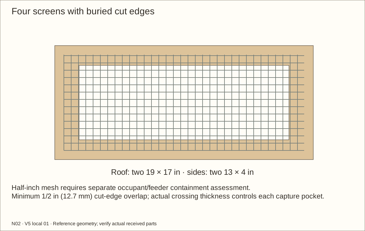
Cut two roof pieces 19 in (482.6 mm) × 17 in (431.8 mm), and two side pieces 13 in (330.2 mm) × 4 in (101.6 mm), from the hardware-cloth roll. Wear eye protection and cut-resistant gloves while handling the cut edges.
Remove projecting wire ends and burrs. Keep a minimum 1/2 in (12.7 mm) mesh margin beyond each opening, fully under the capture strips. Do not leave a sharp wire end exposed to the room.
Check the mesh opening against the future occupant and feeder plan. This 1/2 in (12.7 mm) construction mesh will require a securely retained finer barrier for many occupants; do not treat it as universal animal containment.
Label the two roof pieces and two side pieces. Store them flat until their capture strips are ready.
Check before continuing: All edges are smooth and will be enclosed; none of the four pieces is stretched, rusted or damaged.
Parts: ML, MR, VLB, VLT, VLF, VLA, VRB, VRT, VRF, VRA; use labeled picture and schedules
Tools / setup: Measuring tape, square, pencil and the tools named below
Capture both side screens on solid lands
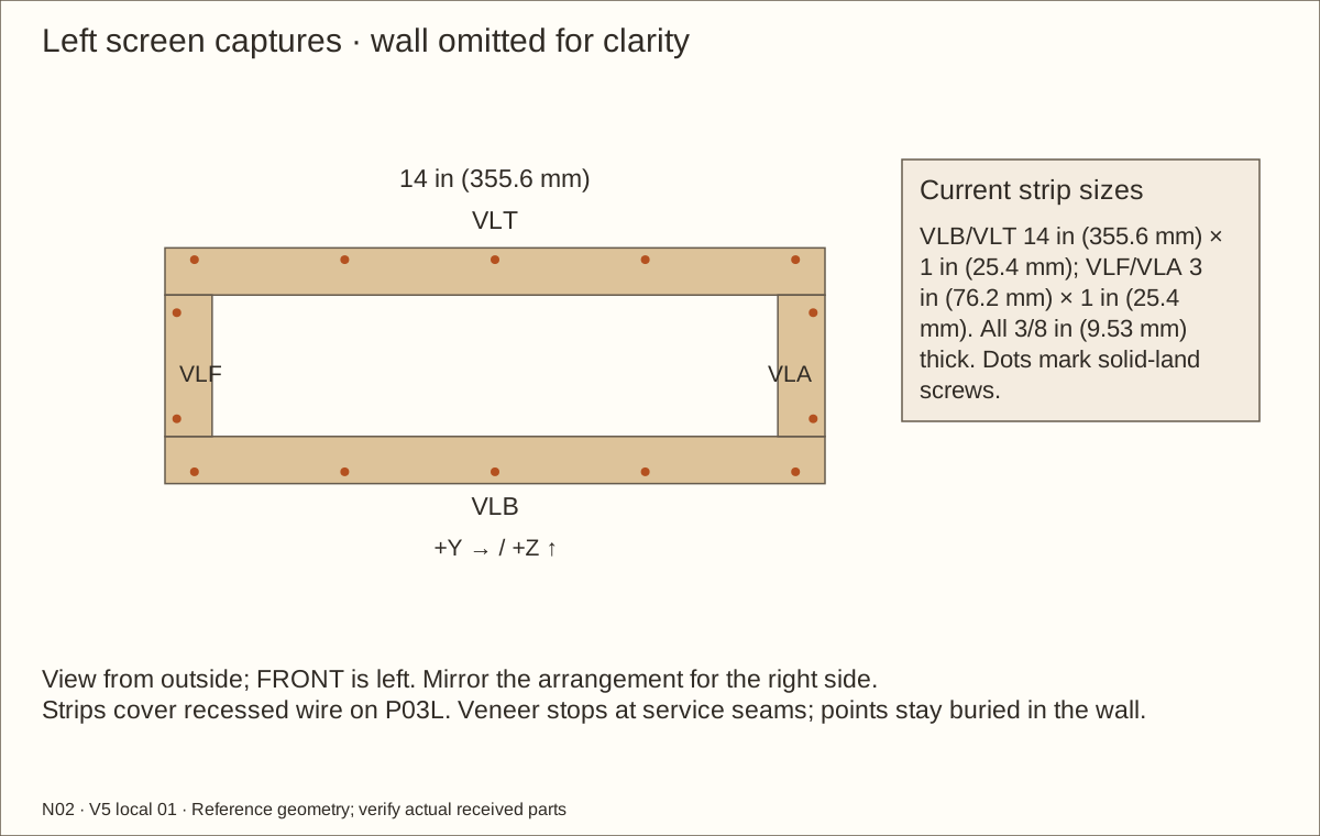
Centre ML/MR over their own wall openings. Dry-seat all four widened captures with their routed pockets facing the wire. The outer solid lands must touch the wall; every wire crossing and cut end must fit inside its pocket.
Clamp the strips flat without bowing wire. Transfer the revised stations on the solid outer lands, outside the wire perimeter. Drill #6 clearance through each strip only, then a stopped pilot into the wall. Do not drill through a wire crossing.
Drive the #6 × 1 in (25.4 mm) screws until the strips hold the mesh firmly. With 3/8 in (9.53 mm) captures and the reference plywood, the points must stay buried; verify from inside after every group.
Run a cloth along the entire interior reveal and gently press the mesh perimeter. Fix any snag or loose edge. Remove the assemblies again during the finishing step, preserving the labels.
Check before continuing: There is no accessible cut wire or loose mesh edge; the opening remains above the fill line.
Parts: P02, CR, MTL, MTR, RTLF, RTLA, RTLL, RTLR, RTRF, RTRA, RTRL, RTRR; use labeled picture and schedules
Tools / setup: Measuring tape, square, pencil and the tools named below
Build the removable screened roof
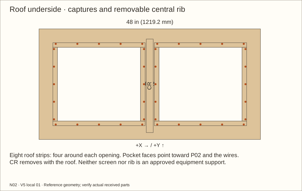
Place the roof underside up on padded supports. Fit CR between the front frame position and rear upper wood support, centred across the roof width. Transfer its top-down #8 screw stations through the roof into the rib.
Centre MTL/MTR under the roof openings. Seat their eight 1 in (25.4 mm) captures with routed pockets toward the wire and solid lands flat against the roof. Transfer the revised outer-land stations, drill clearance through strips and stopped pilots in P02, then fit #6 × 1 in (25.4 mm) screws flush.
Turn the roof with a helper and check every point remains beneath the outer face. The centre rib sits between the openings and ends against the rear wood support; the vent borders stay fully supported.
Dry-seat the roof on the shell and transfer the final roof screw holes. Leave them unfastened until the later access work is complete. The roof and mesh are not shelves; heat and light fixtures require separately supported, specifically qualified equipment.
Check before continuing: The roof sits flat, its wire edges are enclosed and it can lift off without catching the frame.
Tools / setup: Measuring tape, square, pencil and the tools named below
Cut and deburr the accepted profiles
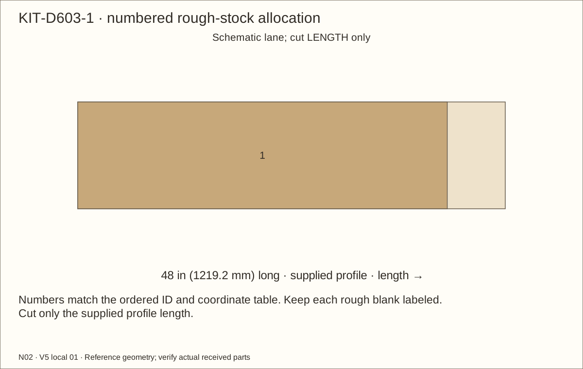
After H01 acceptance, cut two vertical D603A jambs from the separate D603A stock to fit between the lower rail and upper channel. The reference jamb length is 17.16375 in (435.96 mm). Clamp the extrusion with protected jaws, use a square guided metal cut and file every burr. Keep swarf out of channels.
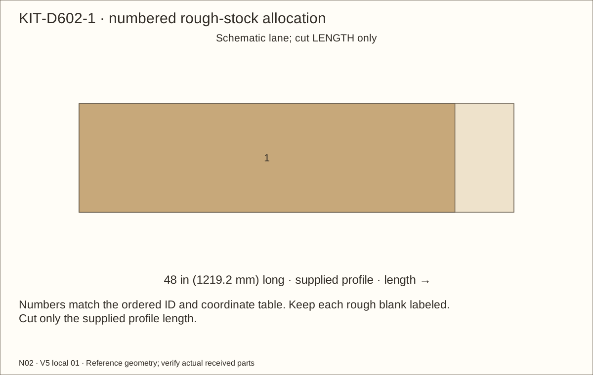
Cut the horizontal D602 and D603 from their designated kit lengths to the accepted cushion-to-cushion fit. Both reference lengths are 41.36275 in (1050.61 mm). Cut each D610 shoe from its own supplied overlapping kit blank after confirming received usable length and shipping cuts, wheel retention and the glass-order allowance. Do not rip a profile to the schematic lane width in a stock drawing.
Check before continuing: Each labeled profile has its accepted fitted length, square ends and no sharp burrs; factory sections and wheel retention are intact.
Tools / setup: Measuring tape, square, pencil and the tools named below
Fit the jambs and approved divider relief
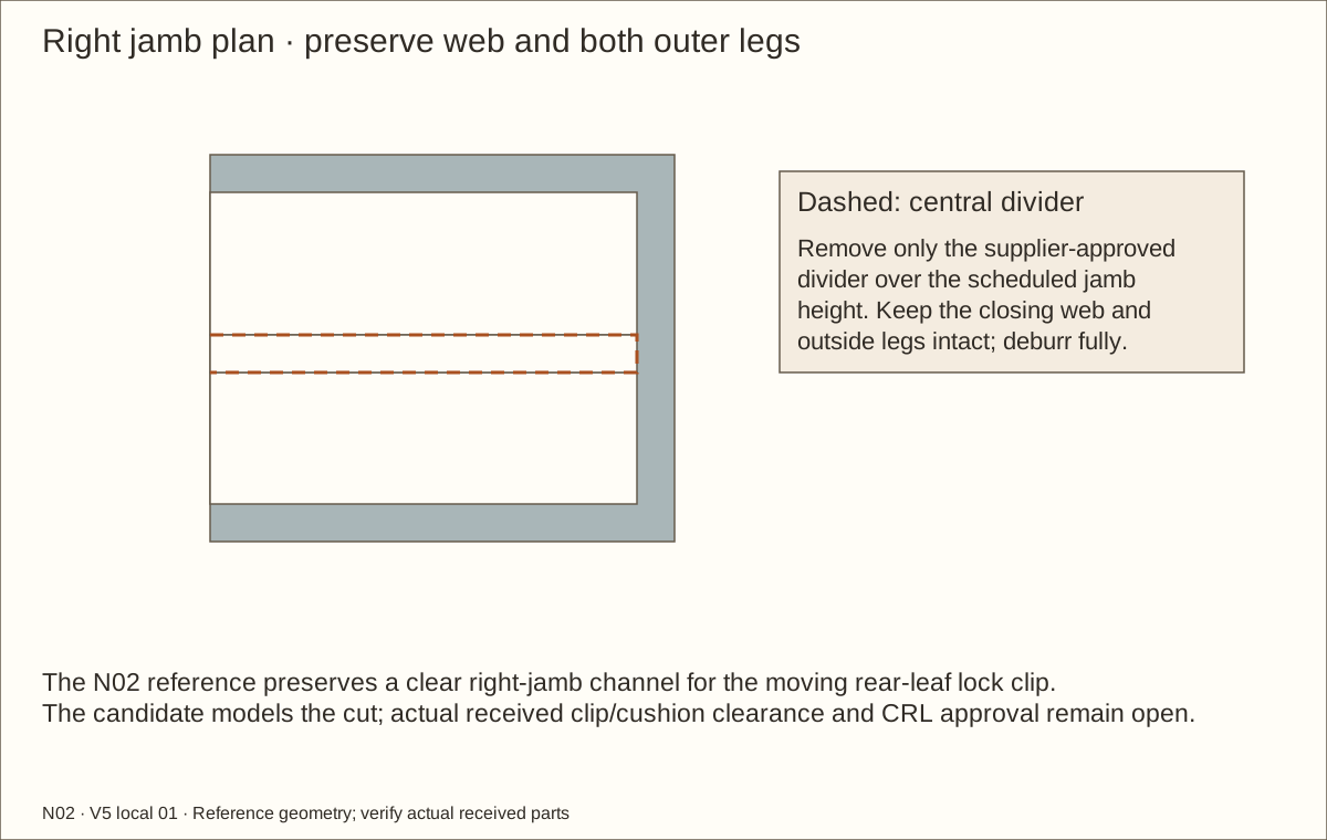
Only after supplier approval, remove the right-jamb central divider over the specified full jamb height, preserving its web and outer legs. Smooth the cut completely. This lets the rear-leaf lock clip approach the closing cushion. Trial the exact clip; if CRL rejects the change, redesign the closure before purchase/construction.
Secure the vertical jamb webs flush: left screws in the front lane, right screws in the rear lane. Use the exact stations. Keep track seats bare and unchanged; veneer and finish must stop at traced bearing footprints.
Check before continuing: Accepted jamb relief is smooth, webs and outer legs are intact, and flush jamb screws leave the guide and closing paths clear.
Tools / setup: Measuring tape, square, pencil and the tools named below
Align and fasten the rolling tracks
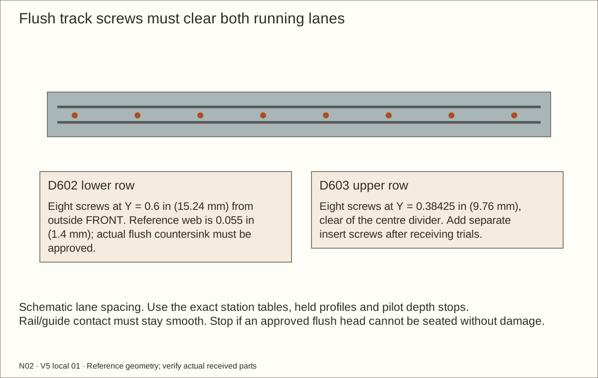
Align D602 with the corresponding D603 lanes using the complete gauge, plumb strip and straightedge. The published lane spacings differ slightly. Transfer the lower-web row at Y = 0.6 in (15.24 mm) and the upper row at Y = 0.38425 in (9.76 mm); upper screws must clear the centre divider. These are assembly distances from the outside front.
Use only supplier-approved thin-web countersinks matching the actual #4 flat heads. Drill clearance through metal, then stopped pilots into the named wood receiver. Fit #4 × 3/4 in (19.05 mm) screws by hand. Eight lower, eight upper and six jamb screws are installed at this stage. Roll both gauge leaves end to end; no head may meet a wheel, guide or glass.
Check before continuing: Both gauge leaves move freely with consistent engagement; mounting heads never touch the wheels or guides.
Tools / setup: Measuring tape, square, pencil and the tools named below
Predrill the removable anti-lift inserts
With the accepted closure gauge and received guide fully seated, measure the free space above each D652 guide. Machine the HDPE strips from broad safely held stock to fit each upper-channel lane, leaving at most 1/16 in (1.59 mm) upward movement. The reference thickness is illustrative; the received guide and extrusion govern.
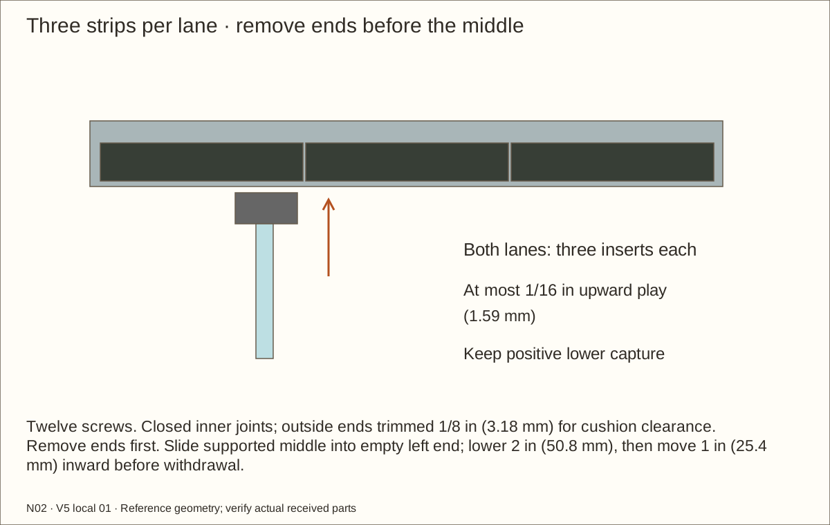
Use three strips per lane, with two closed internal butt joints. The outside ends stop 1/8 in (3.18 mm) short of the former full-lane ends, leaving 0.122 in (3.1 mm) reference clearance to the cured cushions. End-strip length is 13.663 in (347.04 mm); middle length is 13.788 in (350.22 mm). Trial both guides throughout full travel: no guide may escape through a service gap.
Remove glass before transferring the twelve insert stations from the current table. The original eight positions are retained and four inner-end positions are added. Drill clearance through each supported HDPE strip and the accepted upper-track web, then stopped pilots in the named header layer. Countersink the strip heads flush. Mark each ID and orientation; trial the actual driver with panes parked opposite each screw.
Check before continuing: Gauge confirms continuous upper capture; all holes are prepared before coating.
Tools / setup: Measuring tape, square, pencil and the tools named below
Disassemble, sand and mask the wood
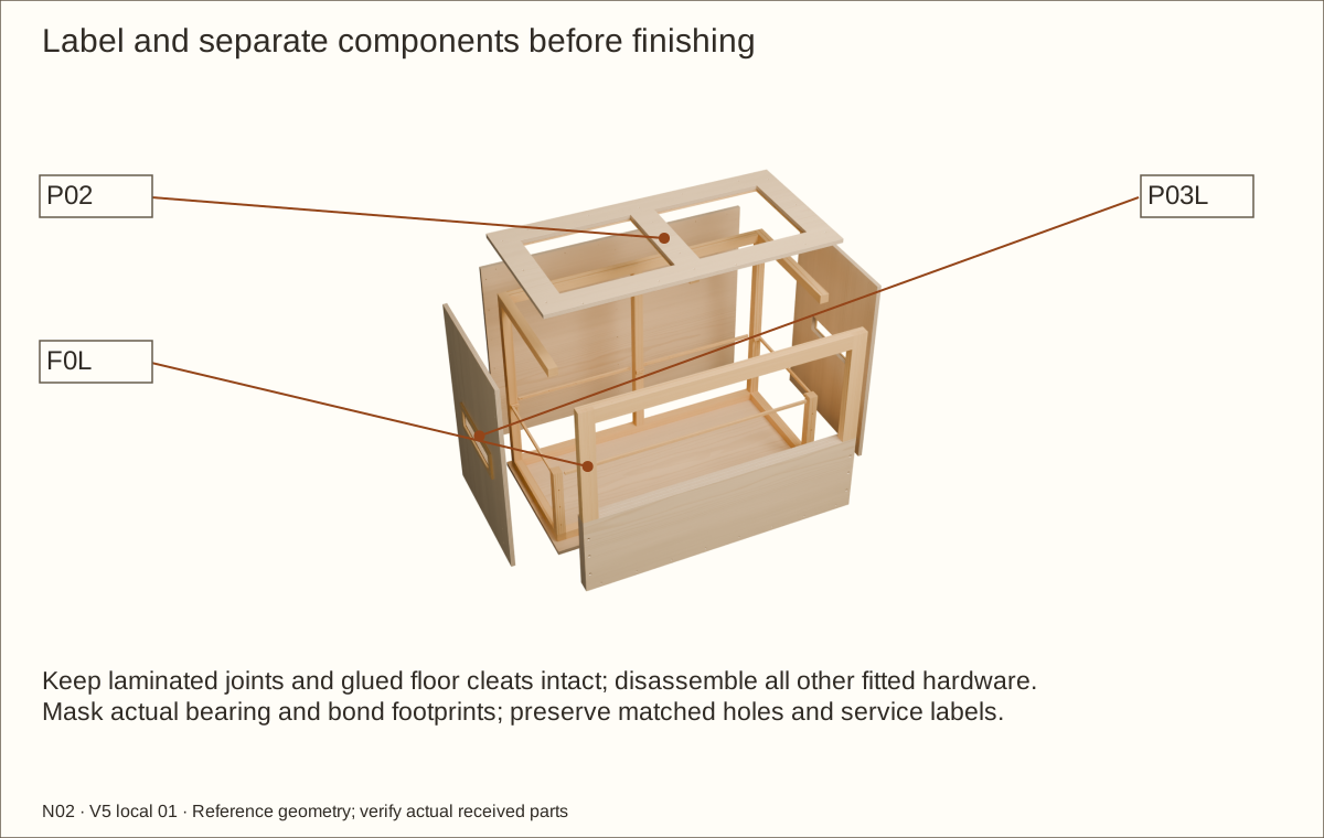
Photograph and label the complete hardware dry fit, including all anti-lift holes, lock and pull positions, and the supported removal trial with the accepted closure gauge and sample. Final panes are ordered only after the cured assembly is measured. Remove hardware, captures, roof, walls, frame and retainer for finishing. Keep the glued floor/cleat and laminated frame/retainer assemblies intact.
Sand from 120 to 220 grit along the grain. Ease all liner-contact edges; vacuum dust and wipe with a clean lint-free cloth. Fill no structural defect with finish; replace damaged material.
Keep glass, rollers, mesh and liner away from sanding and coating. Mask bare glue faces and all actual track/bond/bearing footprints. Use the supplier-approved substrate preparation beneath veneer. No glue joint may rely on an unapproved cured coating.
The calculated one-coat planning area is 219.3 square feet (20.37 square metres), including conservative rectangular wood faces, veneer topcoat, samples and contingency. It needs 5 US quart cans (0.946 L each); buy 3 two-can packs. Extra coats or balancing layers need new quantities.
Check before continuing: Wood is clean and dry, the liner path is smooth and all fittings are labelled for reinstatement.
Tools / setup: Measuring tape, square, pencil and the tools named below
Apply the accepted wood sealer
Check the can is Varathane Triple Thick clear satin water-based polyurethane, manufacturer 284473. The selected Lowe’s pack contains two quart cans. Stir; do not shake. Follow the received label and use a quality synthetic-bristle brush.
Apply the manufacturer-approved sealer/topcoat sequence to the exposed wood, edges and reveals, while keeping all marked bare bearing and bond seats masked. The label application range is 60–90°F (16–32°C) below 85% relative humidity. Use ventilation and label protective equipment. The veneer supplier must accept the actual cured substrate.
Check before continuing: Correct product and conditions; every required face and reveal coated, masked seats preserved.
Required wait: Follow the received application and recoat directions; the full cure is recorded in the next operation.
39. Record and complete the wood coating’s full cure
Parts: Named parts shown in the picture
Tools / setup: Measuring tape, square, pencil and the tools named below
Record and complete the wood coating’s full cure
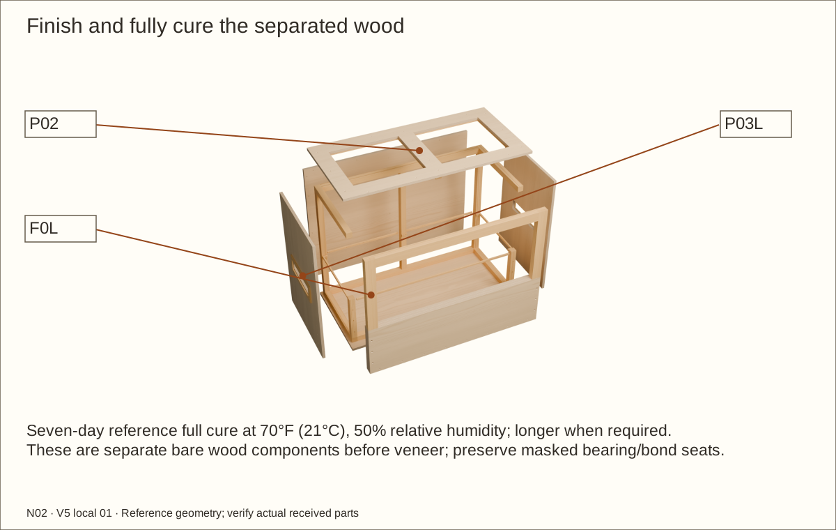
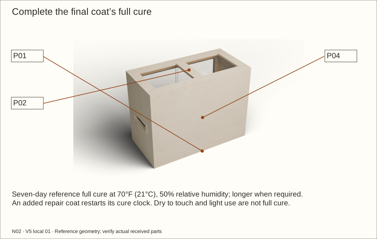
Record the time and conditions of the final applied coat. Full cure is seven days at 70°F (21°C) and 50% relative humidity (RH) with ventilation; adverse conditions need longer under the manufacturer’s directions. Two-hour recoat and 48-hour light-use times are not full cure.
If repair coverage is needed, follow the 220-grit intercoat preparation and recoat instructions; add its coat area to the quantity record and restart the final-coat cure clock. Inspect the dry film for missed end grain, runs, tackiness and damage.
This coating protects an ordinary indoor wood shell. The separate liner takes the damp bed; do not rely on polyurethane or wood glue as an immersed joint seal.
Check before continuing: The recorded full-cure period has passed under suitable conditions and every coated surface is intact.
Required wait: Full cure: seven days at 70°F (21°C), 50% relative humidity (RH); longer when required
Parts: Veneer trial piece and complete finishing system
Tools / setup: Measuring tape, square, pencil and the tools named below
Approve the complete veneer sample
Use the actual substrate, sealer, selected veneer/backer/PSA and topcoat on a spare piece. PSA means pressure-sensitive adhesive. Supplier instructions control cleaning, acclimation, application pressure and dwell; no unsupported dwell time is substituted.
Measure the whole cured layer. The reference is 0.0305 in (0.77 mm); maximum 0.046 in (1.17 mm) before this design must be recalculated. Confirm one-sided panel balance and inspect after the intended humidity, heat and cleaning exposure.
Keep metal and cushion-bond footprints bare. The sample must remain flat and well bonded, with no lifting corners, bubbles or coating damage. Record the supplier-approved wait and the completed result.
Check before continuing: Approved sample is flat, secure and within the coordinated stack limit.
Required wait: Complete supplier-confirmed acclimation and adhesive dwell plus the received topcoat full cure.
Tools / setup: Measuring tape, square, pencil and the tools named below
Cut and apply the matching edge strips
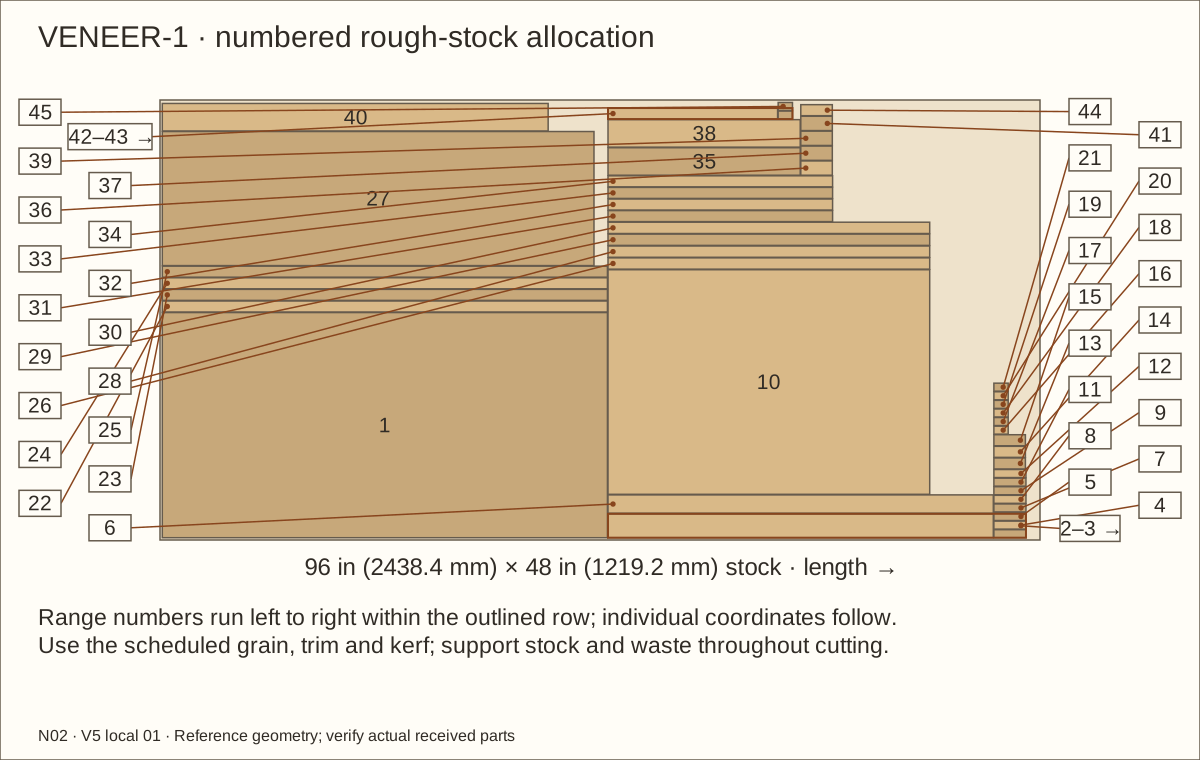
Use the VENEER layouts and labeled V-pieces. Put grain along each scheduled grain axis. Cover the floor/roof edges, exposed wall edges, roof-opening reveals, vent lips and external capture edges before their broad faces.
Cut oversized blanks on a sacrificial board with a sharp knife and straightedge. Use repeated shallow passes; keep fingers behind the cut. Transfer actual traced bearing footprints before peeling backing.
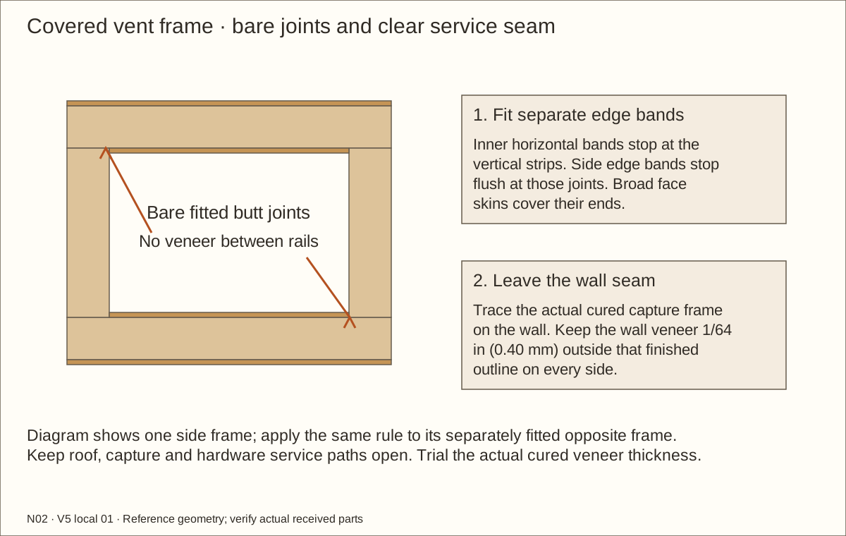
Apply the accepted PSA system with the specified firm scraper/pressure. Support fibers while trimming flush, then ease edges lightly. Do not bend veneer around a sharp plywood edge or bridge a removable seam. Stop vent edge bands at bare fitted butt joints; keep wall skins 1/64 in (0.4 mm) outside the finished capture-frame outline.
Check before continuing: Exposed plywood layers are covered; hardware seats and service seams remain usable.
Parts: All face V-pieces; separate roof, body and captures
Tools / setup: Measuring tape, square, pencil and the tools named below
Veneer the complete outside faces
Apply the scheduled roof top, floor underside, sides, back, front frame, retainer front and external capture faces. Face veneers cover the ends of their matching edge strips. Keep roof grain straight and widthwise, including the front edge.
Trace openings from the actual parts, cut from the supported side and preserve all margins. Keep separate skins on the removable roof and each capture. Do not cover an assembly screw or the bare track footprint.
Open the scheduled full-depth screw-head access holes with supported tooling after the dry trial. Heads remain flush on their original wood datum. Inspect all outside corners and reveals before the final topcoat.
Check before continuing: Uniform chosen species covers faces, roof and edges without blocking removal or rolling hardware.
Tools / setup: Measuring tape, square, pencil and the tools named below
Topcoat veneer and finish the full cure
Use the supplier-approved topcoat on the accepted veneer system. Protect marked track, cushion-bond and bare bearing seats; keep all service holes clear. Record application conditions and final coat time.
The selected coating’s reference full cure is seven days at 70°F (21°C) and 50% relative humidity. Follow the received label if conditions require longer. Recoat/light-use times do not establish full cure.
Inspect for bubbles, lifted edges, runs, tackiness and warp. Repair using an approved method and restart the affected cure clock. Recheck total layer thickness and flatness before final assembly.
Check before continuing: All affected surfaces are fully cured, flat and intact.
Required wait: Seven-day reference full cure after the final coat; longer when actual conditions or the received label require.
Tools / setup: Measuring tape, square, pencil and the tools named below
Before you begin: Reference glass dimensions are not a blind ordering instruction.
Reassemble the cured body and tracks
Reassemble the labelled shell, two front posts, six complete flush machine-screw sets, frame, captures and tracks in their matched holes. Reach interior nuts before underlay and liner cover them. Recheck threads and recessed tips without crushing cured wood or finish. Confirm full support, diagonals, flat bearing lands, alignment and the accepted closure-gauge removal trial.
Check before continuing: The cured shell is square and supported, captures bear flat, and reinstalled tracks pass the accepted gauge and removal trials.
Parts: STOPLF/STOPLB/STOPRF/STOPRB and accepted contact bond
Tools / setup: Measuring tape, square, pencil and the tools named below
Bond the four accepted jamb cushions
Use DAP Weldwood Original 00271 only after CRL/DAP approval of the received anodized aluminium and plain neoprene. Trial cleaning and two-face coating on matching offcuts. Never use this bond on EPDM, glass or HDPE.
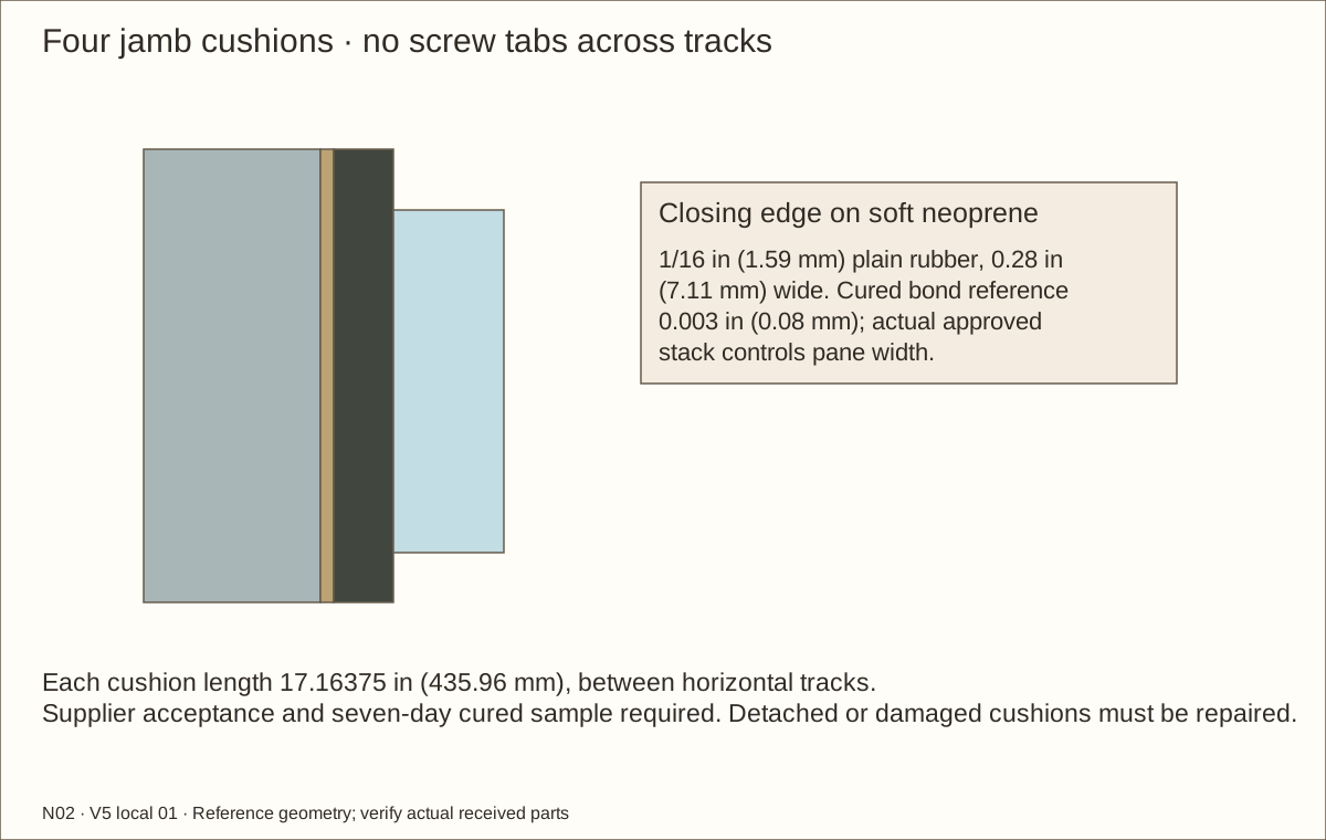
Cut four 17.16375 in (435.96 mm) × 0.28 in (7.11 mm) × 1/16 in (1.59 mm) strips. They fit between the horizontal tracks, with no tabs across the rails. Mask adjacent channels and apply the accepted thin contact-bond film by its label.
Fit each strip on its named jamb lane, press as specified and leave it undisturbed. The model film is 0.003 in (0.08 mm); measure the actual cured stack before glass sizing. Reject lifting edges or movement during repeated sample closing/service trials.
Check before continuing: Four cushions are secure, correctly placed and clear of track/guide paths.
Required wait: Seven days to the published maximum-strength reference; follow actual label and supplier requirements.
Tools / setup: Measuring tape, square, pencil and the tools named below
Before you begin: Reference glass dimensions are not a blind ordering instruction.
Measure and release the final glass order
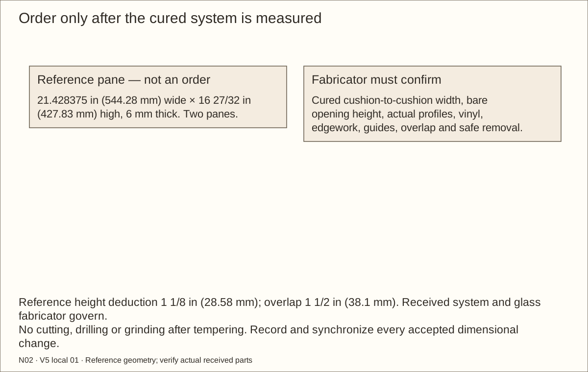
Install the four accepted bond-retained cushions between the horizontal tracks and complete their full cure. Then measure the smallest width between their cured contact faces and the bare seat-to-seat opening height. Give the glass fabricator the actual track, shoe, vinyl, guide and lock samples with those measurements.
Reference pane size is 21.428375 in (544.28 mm) wide × 16 27/32 in (427.83 mm) high × 6 mm thick, approximately 7.7 lb (3.49 kg) per pane. These are NOT order dimensions. Width starts from (measured cushion-to-cushion width + accepted overlap) ÷ two; height starts from measured bare opening minus the accepted profile deduction. The fabricator confirms all final allowances.
Resolve the GC728C listing conflict before glazing: the kit recommends it for 6 mm glass while the current vinyl page lists a different glass-thickness range. CRL must identify the exact received vinyl and fit. Confirm polished edges, corner treatment, tolerances and monolithic tempered glass. All fabrication happens before tempering; never drill, trim or grind a tempered pane on site.
Record both accepted final pane cuts and revise the coordinated specification if they differ. The complete D2203A48 kit suggests no more than 36 in (914.4 mm) × 48 in (1219.2 mm) per panel. No numerical mass capacity was established for these two-wheel reference panes. This smaller two-roller reference pane is about 2.506 square feet (0.233 square metres). That comparison is not a load rating or approval of the altered closure.
Check before continuing: The final measured opening, exact profiles and supplier-confirmed glass cuts are recorded; the panes are within the kit’s stated size guidance.
47. Lay protective underlay and the one-piece liner
Parts: LINER, LCL, LCR, LCF, LCBL, LCBR, LCM, LCQL, LCQR, LCPL, LCPR; use labeled picture and schedules
Tools / setup: Measuring tape, square, pencil and the tools named below
Lay protective underlay and the one-piece liner
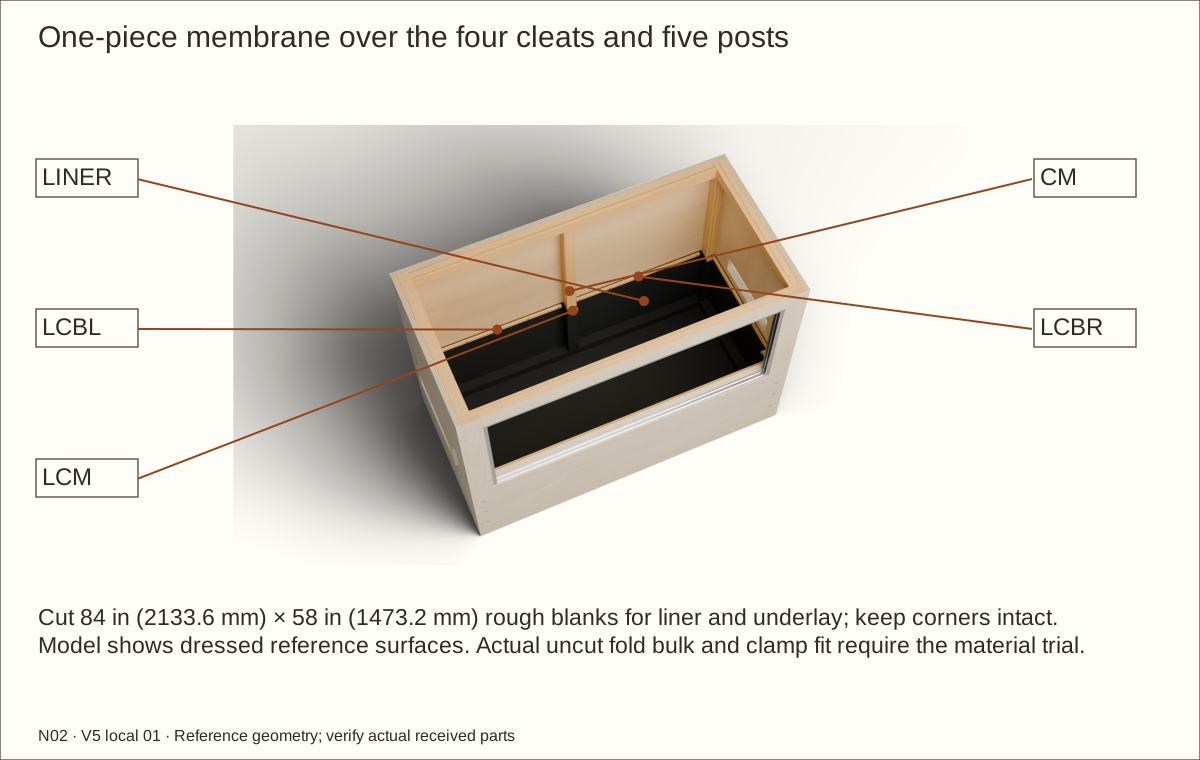
With roof and doors off, cut one 84 in (2133.6 mm) × 58 in (1473.2 mm) underlay blank and one matching EPDM blank. Keep their centers marked and corners intact. Vacuum the clean floor and dress every sharp support edge. The larger rough blank allows folding and handling; it is not the installed basin size.
Lay the soft underlay over every contact face, including the central floor, four cleat shelves and all five front/rear posts. Place supplementary loose protective pads over each recessed nut pocket; actual bulk must fit without pulling the liner tight. Place the liner above it with slack. Work from the floor center outward; do not stretch it between supports or hang it from clamps. The model separately shows the reference protective layer.
Check before continuing: Underlay covers every hard contact and the intact liner lies slack over all five post returns.
48. Fold corners and mark the actual liner heights
Parts: LINER, LCL, LCR, LCF, LCBL, LCBR, LCM, LCQL, LCQR, LCPL, LCPR; use labeled picture and schedules
Tools / setup: Measuring tape, square, pencil and the tools named below
Fold corners and mark the actual liner heights
At each corner, raise an uncut diagonal ear. Dress the liner over the cleats and around both front posts and all three rear uprights on their room-facing surfaces; never force it through or behind a fixed post. Fold surplus into upright pleats; do not slit, staple or splice below the upper dry clamping band. Use the actual-material trial to decide the fold direction and bulk.
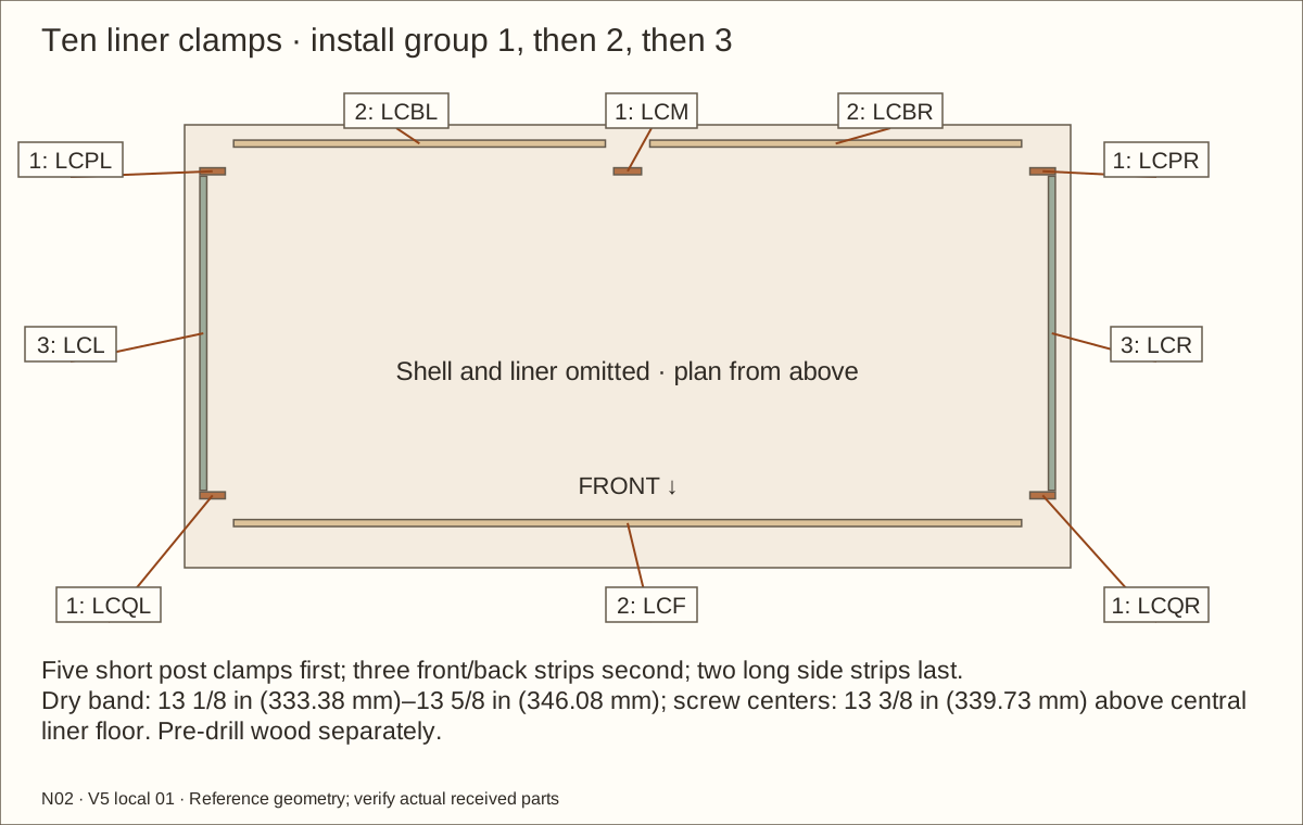
Check the actual central finished-floor elevation with a straightedge and depth gauge. Mark maximum total bed 12 in (304.8 mm) above it, clamp screw centers 13 3/8 in (339.73 mm) above it and final liner top 13 3/4 in (349.25 mm) above it. If the compressed/folded stack changes those positions or clamp bearing, stop and revise the dimensions. Keep liner below the retainer top and clear of tracks.
Check before continuing: Uncut folds fit without tension; bed, clamp and top lines are transferred from the measured central liner floor.
Parts: LINER, LCL, LCR, LCF, LCBL, LCBR, LCM, LCQL, LCQR, LCPL, LCPR; use labeled picture and schedules
Tools / setup: Measuring tape, square, pencil and the tools named below
Fasten the ten removable liner clamps
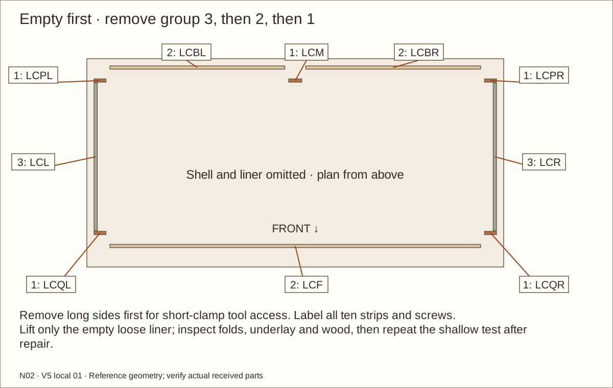
Install all five short rounded post clamps LCQL/LCQR and LCPL/LCM/LCPR first while the long side clamps are absent; this preserves straight driver access. Then fit LCBL/LCBR and LCF, followed by LCL/LCR. Dry-fit the actual folds beneath each strip before holes. Transfer the exact screw centers halfway across each 1/2 in (12.7 mm) strip; only the scheduled screws pierce the upper dry band, from 13 1/8 in (333.38 mm) to 13 5/8 in (346.08 mm) above the actual central liner floor; their centers are 13 3/8 in (339.73 mm) above that floor. The basin below 13 1/8 in (333.38 mm) remains uncut and unpunctured.
Pre-drill clearance through each held wood clamp and a stopped #6 pilot in its wood receiver with the liner lifted away. Return the liner and underlay, then make only the scheduled small screw punctures by hand under the clamp. Never drill loose membrane around a rotating bit. Fit the listed #6 × 1 in (25.4 mm) screws without crushing or cutting the liner. Round clamp edges, keep corners smooth and check buried tips. Trim excess only above the final top line after the entire dry fit is accepted.
Check before continuing: All ten clamps are secure in the stated order; only scheduled dry-band screws pierce the lining and the basin below stays intact.
Parts: LINER, LCL, LCR, LCF, LCBL, LCBR, LCM, LCQL, LCQR, LCPL, LCPR; use labeled picture and schedules
Tools / setup: Measuring tape, square, pencil and the tools named below
Complete the 24-hour shallow liner check
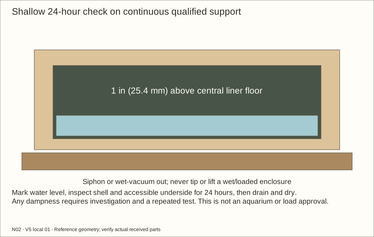
On qualified continuous support, add 1 in (25.4 mm) of water above the central floor for 24 hours before substrate. Mark the level and inspect the shell/accessible underside for dampness. The rectangular upper water estimate is 4.23 US gallons (16.0 L); cleats displace some water. This is a shallow leak check, not aquarium approval.
Siphon or wet-vacuum the water out; never tip the box. Dry it and investigate any moisture, tears, stressed folds or moved clamps. Repair or replace the membrane using an accepted method, then repeat the full check. Do not cover a failed test with substrate.
Check before continuing: The recorded 24-hour shallow test shows no leak or shell dampness; water is removed and the liner and shell are dry.
Required wait: Inspect a 24-hour shallow water test before filling
Parts: GL, GR, HL, HR, WHL1, WHL2, WHR1, WHR2, TGL1, TGL2, TGR1, TGR2; use labeled picture and schedules
Tools / setup: Measuring tape, square, pencil and the tools named below
Glaze each shoe and fit its wheels and guides
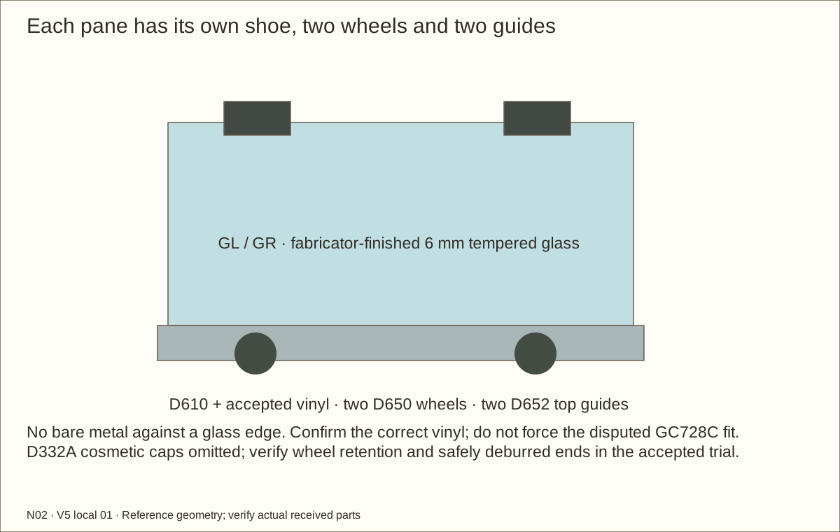
Inspect the fabricator-supplied tempered panes for chips and cracks on a clean padded bench with a helper. Fit the supplier-confirmed glazing vinyl in each D610 shoe and seat the glass evenly using received instructions. Do not force a disputed vinyl or let bare metal touch a polished glass edge.
Install two D650 wheel assemblies and two D652 guides per pane at the accepted gauge positions. Wheel centers reference 1 1/2 in (38.1 mm) from each glass end. Deburr uncapped shoe ends and check the assemblies cannot shift or work out; the optional D332A cosmetic caps are not part of this candidate.
Check before continuing: Each supported pane is undamaged; accepted vinyl separates glass from metal, and both wheels and guides are securely retained.
Parts: GL, GR, HL, HR, WHL1, WHL2, WHR1, WHR2, TGL1, TGL2, TGR1, TGR2; use labeled picture and schedules
Tools / setup: Measuring tape, square, pencil and the tools named below
Seat the rear leaf, then the front leaf
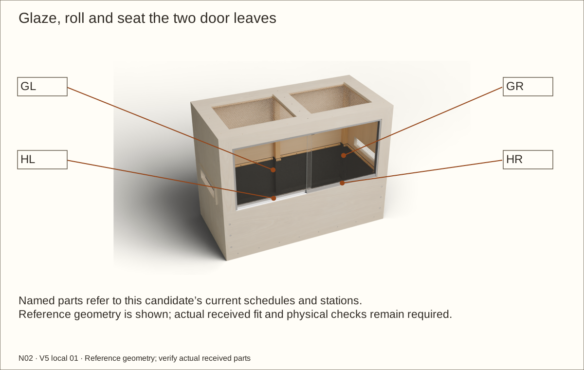
Insert the left closing leaf into the rear upper channel first, lift it, bring the roller shoe over the corresponding lower rail and lower gently. Install the right closing leaf in the front lane in the same way. Do not let the pane twist.
Move each leaf through its entire path and check the 1 1/2 in (38.1 mm) closed overlap. Inspect the guide engagement at both ends and the middle. The panes must not rub one another, a mounting head or a wood edge.
Check before continuing: Both doors roll without binding and remain seated throughout their travel; there is no glass-edge damage.
53. Install anti-lift inserts around the parked panes
Parts: ALF1/ALF2/ALF3 and ALB1/ALB2/ALB3; twelve #4 × 3/4-inch screws
Tools / setup: Measuring tape, square, pencil and the tools named below
Install anti-lift inserts around the parked panes
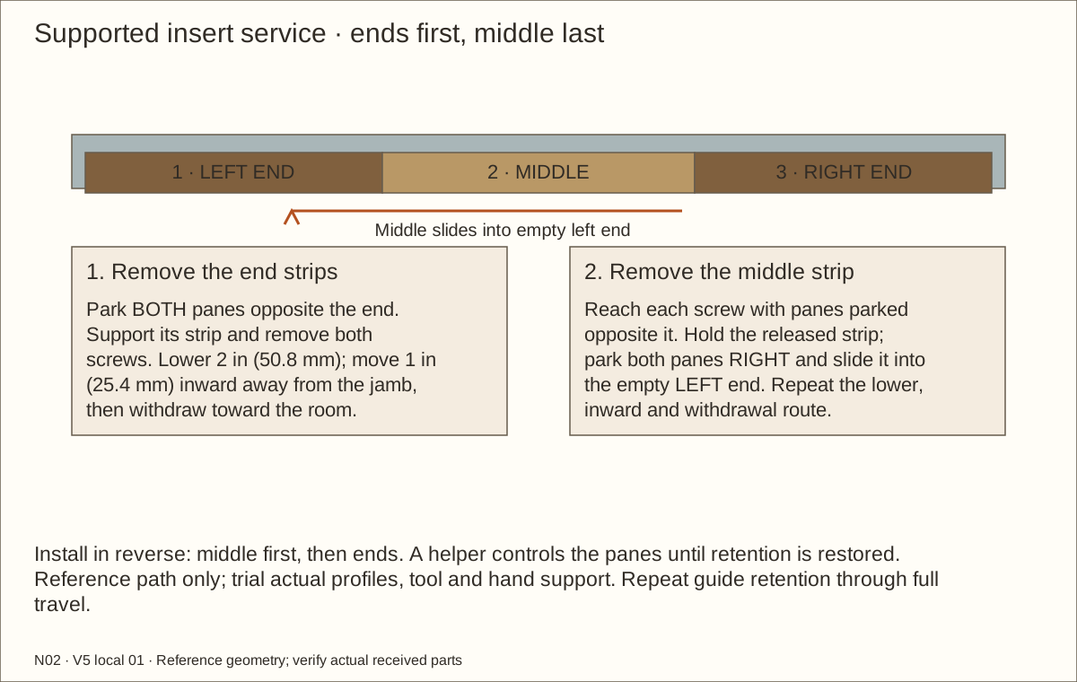
With the lock removed and a helper controlling both seated panes, park both panes to the RIGHT. Bring the middle strip into the vacant LEFT opening 2 in (50.8 mm) below its channel and 1 in (25.4 mm) in from the jamb; move it toward the jamb, then raise it into the empty LEFT end of its lane and slide it into the middle above the guides. Hold it while fitting its left screw. Park panes LEFT to reach the right screw; retain positive support throughout.
Fit the left end strip with both panes RIGHT, then the right end strip with both panes LEFT. Repeat for the other lane. Keep both internal joints closed and leave only the specified outer service gaps. Use the twelve exact stations and accepted driver; never force a strip against a guide or glass.
For removal, support the panes and remove the left and right end strips first, parking both panes opposite the end being worked on. Release both middle screws from their accessible pane positions. Park panes RIGHT, slide the supported middle into the empty LEFT end, lower it 2 in (50.8 mm), move it 1 in (25.4 mm) inward away from the jamb, then withdraw it toward the room. Use the same lower-and-move-inward route for each end strip. Remove all strips before lifting a pane.
Check before continuing: Both lanes retain the guides through full travel; joints, outer gaps, driver access and supported strip removal pass the actual dry trial.
Tools / setup: Measuring tape, square, pencil and the tools named below
Prove cushion and anti-lift retention
Check all four cured bond-retained jamb cushions. They end between the horizontal tracks and have no screw tabs. Each closing glass edge must meet soft rubber without striking a head or sharp lip. A detached cushion requires repair, full cure and renewed fitting checks.
At both ends and the middle of travel, gently lift each pane. It must remain positively engaged on the lower rail, with the top guide retained. Remove the inserts to demonstrate safe service removal, then reinstall them. If the pane can clear its lower rail with the inserts fitted, correct the profile fit before proceeding.
Check before continuing: Neither pane can be lifted off its rail in any operating position; both remain removable after the inserts are unscrewed.
Tools / setup: Measuring tape, square, pencil and the tools named below
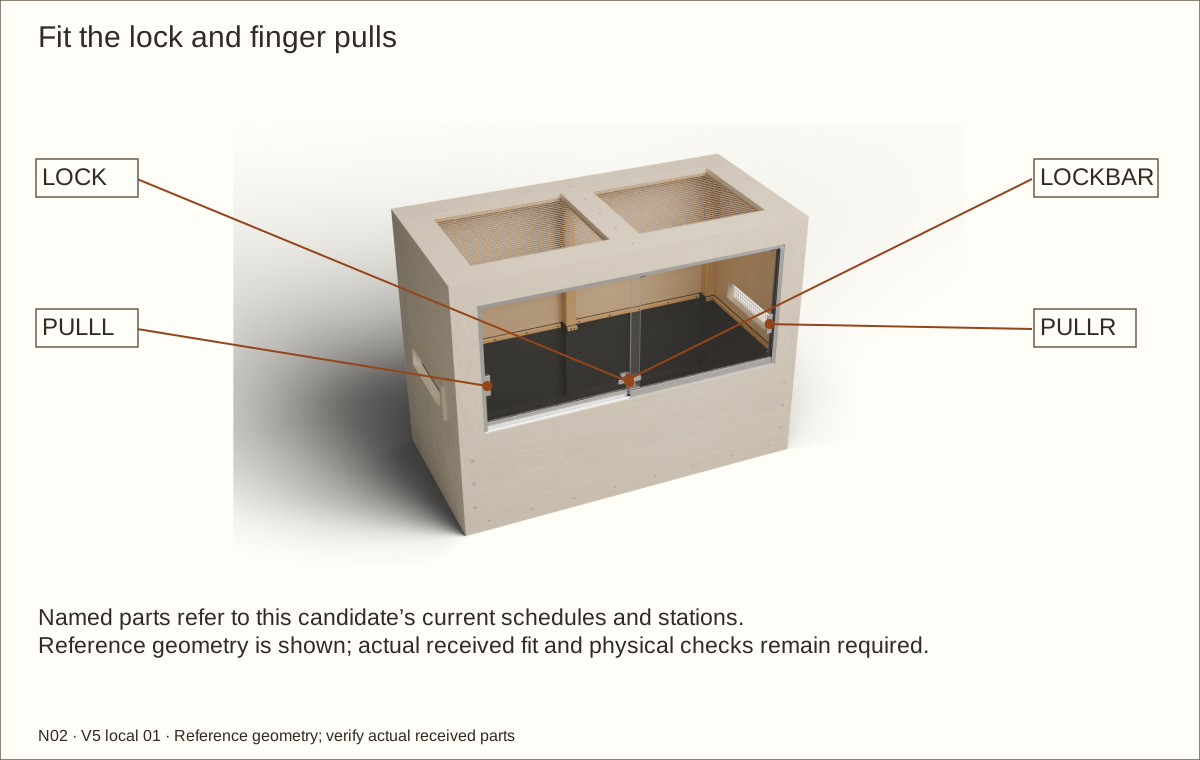
Fit and test the ratchet lock
Close both doors on their cushioned jamb stops. Fit the 963L ratchet bar to the rear leaf and its anti-spread housing across the overlap following the supplied orientation. Protect the polished edge; no improvised metal packing may touch glass.
Adjust the ratchet to secure both leaves without forcing or bowing them. With the key removed, gently test each door separately for sliding, spreading and lifting. The anti-lift inserts remain installed independently of the lock.
Check before continuing: The lock holds both closed leaves and releases predictably without forcing the glass; independent anti-lift inserts remain fitted.
Tools / setup: Measuring tape, square, pencil and the tools named below
Fit the pulls and measure service access
Clean the pull locations using the pull maker’s instructions. Place each FP86 near its closing edge, away from the lock and shoe, and confirm the complete bypass path before bonding. Follow the adhesive preparation and dwell time on the received product.
Unlock and remove the lock body before moving a pane. The reference single-leaf access is 19.367875 in (491.94 mm) wide × 17.16375 in (435.96 mm) high. Plan at least 18 in (457.2 mm) width for service; larger objects require both panes or roof removed. The rear-leaf ratchet clip stops against the opposite rear-lane cushion, before the metal jamb. Measure this with the received clip; never force travel beyond the stop.
Check before continuing: The lock holds both closed leaves and releases predictably; pulls do not collide and service access is documented.
Required wait: Complete the received pull adhesive preparation and dwell before using the handles.
Tools / setup: Measuring tape, square, pencil and the tools named below
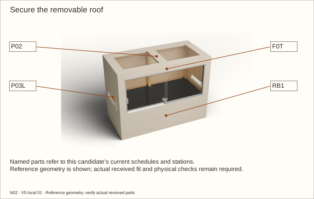
Secure the removable roof
Check that mesh, liner clamps and track hardware are complete before setting the roof down. Seat it without trapping the liner, glass guides or future cables.
Use the transferred roof stations: three screws along each side wood support, four across the front header and four across the rear upper wood support. Drill clearance through P02 and stopped pilots into the receivers.
Fit #8 × 1 1/4 in (31.75 mm) screws, tightening evenly by hand. Do not glue the roof and do not use the mesh as a handle. Check the doors again with the roof secured.
Keep the roof screw locations accessible in the final equipment arrangement. Remove equipment and disconnect power before roof service; support equipment independently of the screen.
Check before continuing: The roof cannot shift or lift unintentionally, and both doors still operate without binding.
Tools / setup: Measuring tape, square, pencil and the tools named below
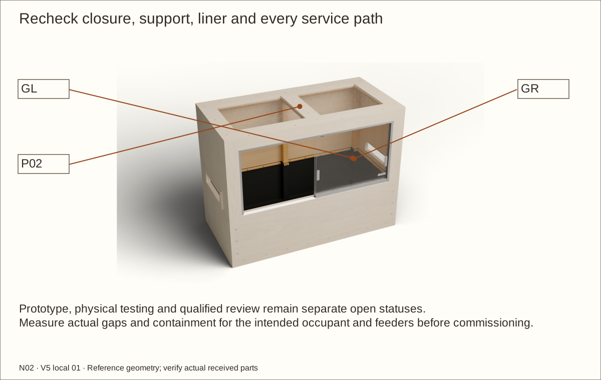
Inspect construction and rehearse maintenance
Check every scheduled screw, all six recessed retainer nut stacks, complete thread engagement, screen captures, polished glass, roof perimeter, lock and anti-lift inserts. Repair splits, burrs, loose fittings and stripped receivers. Keep exterior retainer drives accessible. Inside access requires removal of the empty liner and underlay.
Measure the closed gaps at the jambs, between the glass leaves, below the shoes, around the roof and at the mesh. Record actual values; the construction clearances alone do not establish containment for an animal or feeder.
Verify the cured finish and dry shell after the liner test. Check that no below-fill screw or cable has penetrated the basin and that the removable liner clamps are accessible.
Rehearse removing and reinstalling the lock, anti-lift inserts, both panes and roof with the enclosure empty. Confirm that the cleaning tools can reach the rear corners and that the full bed can be removed without tipping the box.
Check before continuing: The completed construction record has no unresolved defect. Animal and equipment commissioning remains a separate step.
Parts: Both glazed leaves, lock and removable inserts
Tools / setup: Measuring tape, square, pencil and the tools named below
Remove and refit glass for service
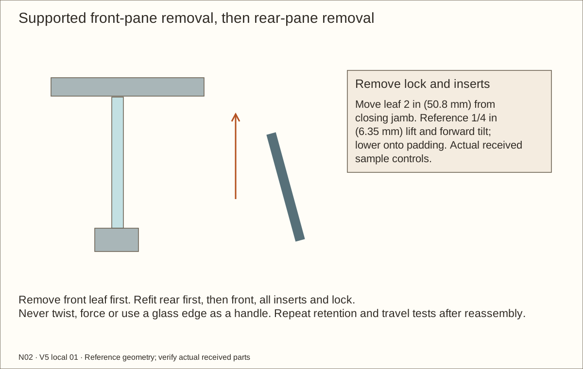
Empty the enclosure and disconnect/remove equipment. With a helper supporting the glass, remove the lock body and both lanes of anti-lift inserts. Support the front leaf first, then the rear; never use the edge as a lifting handle.
Move the front leaf 2 in (50.8 mm) away from its closing jamb. The reference path lifts 1/4 in (6.35 mm), tilts the bottom toward the room and lowers onto padding. Actual accepted profile clearance controls; never force glass. Repeat for the rear leaf after the front one is safely removed.
Vacuum and wipe tracks without flooding; dry them immediately. Refit rear pane first, then front. Reinstall all inserts and lock and repeat full travel, closed-gap and anti-lift tests before returning an occupant.
Check before continuing: The complete empty service route is clear and retention passes after reassembly.
Parts: Ten liner clamps, empty EPDM sheet and underlay
Tools / setup: Measuring tape, square, pencil and the tools named below
Remove and inspect the liner for maintenance
Remove animals and equipment, then scoop the full bed into containers without tipping the box. Remove the panes or roof as needed for reach. Never pull a liner loaded with substrate or water.
Remove long side clamps first to reach the short front and rear post clamps. Label all ten strips and screws. Release the folds gently, lift the empty liner and underlay and inspect the floor, cleat edges and every membrane fold.
Dry and repair the cause of dampness or abrasion. Replace damaged material or use a manufacturer-accepted repair, complete all cure waits and refit with short post clamps first. Repeat the 24-hour shallow liner check and closure checks before refilling.
Check before continuing: All surfaces are sound and dry; repaired/reinstalled liner passes the repeated shallow check.
Tools / setup: Measuring tape, square, pencil and the tools named below
Place and measure the total bed
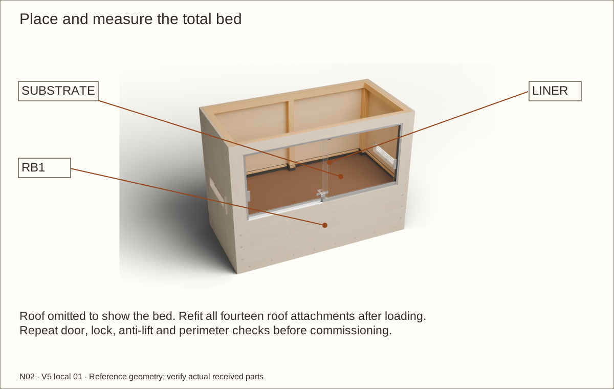
Place the enclosure permanently on its qualified full-footprint support before filling. Add smooth protective pads under hard decorations, spreading their loads without puncturing the liner. Do not place a sharp rock directly on the membrane.
Measure the entire bed from the finished central liner floor. A drainage layer, separator and substrate all count toward 12 in (304.8 mm); for example, 2 in (50.8 mm) drainage leaves at most 10 in (254 mm) for the remaining layers.
The reference uninterrupted floor rectangle between lined supports is 43 11/32 in (1100.93 mm) × 17 15/16 in (455.61 mm), about 5.4 square feet (0.5 square metres). Above the maximum 12 in (304.8 mm) total bed, the clear height below upper supports is 20 31/32 in (532.61 mm), before equipment or furnishing deductions. Measure the received construction.
Weigh the delivered damp mix and record the total installed load. Check support deflection, doors and liner after filling; remove the bed if anything shifts or binds. The density scenarios are planning arithmetic, not a structural rating.
The picture omits the roof to show the bed. If removed for loading, refit all fourteen roof attachments and repeat door, lock, anti-lift and perimeter checks before commissioning.
Check before continuing: The total bed stays at or below its line, with 2 in (50.8 mm) retaining-wall space above the bed and documented remaining usable space.
Tools / setup: Measuring tape, square, pencil and the tools named below
Qualify the actual occupant and equipment
Select the intended species, life stage and number of occupants against current care requirements using the finished usable interior, not the nominal 48 in (1219.2 mm) × 24 in (609.6 mm) × 36 in (914.4 mm) shell. This generic guide assigns no species suitability.
Qualify every gap and the mesh opening for the occupant and feeders. Add a mechanically retained finer barrier when needed, then reassess ventilation, visibility, cleaning and equipment performance.
Choose heat, light, ultraviolet and control equipment for the actual habitat. Follow their exact mounting, separation and combustible-clearance instructions; use an independent support for fixtures. Keep hot parts away from wood, liner, glass and animal contact, and do not load the mesh.
Check before continuing: The intended species, life stage, usable space, equipment supports and cable routes are recorded before commissioning.
63. Commission the configured habitat before entry
Parts: Named parts shown in the picture
Tools / setup: Measuring tape, square, pencil and the tools named below
Commission the configured habitat before entry
Plan any cable penetration against the exact connector and strain relief before cutting. Put it above the liner, seal and finish its wood reveal, then fit a retained closure that cannot be pushed open. Do not trap a cord in the roof joint or make a new hole through the wet basin. Complete the affected coating’s full cure after sealing a new opening before equipment testing or animal entry.
Run the complete configured habitat unoccupied through its planned day/night and wet/dry cycles. Measure the relevant temperatures, humidity, ventilation and light exposure; verify thermostat control, safe surfaces, door retention and cleaning access. Record passing results before animal entry.
Check before continuing: Animal entry follows a separate, documented species/equipment commissioning review; a finished wooden shell is not that approval.
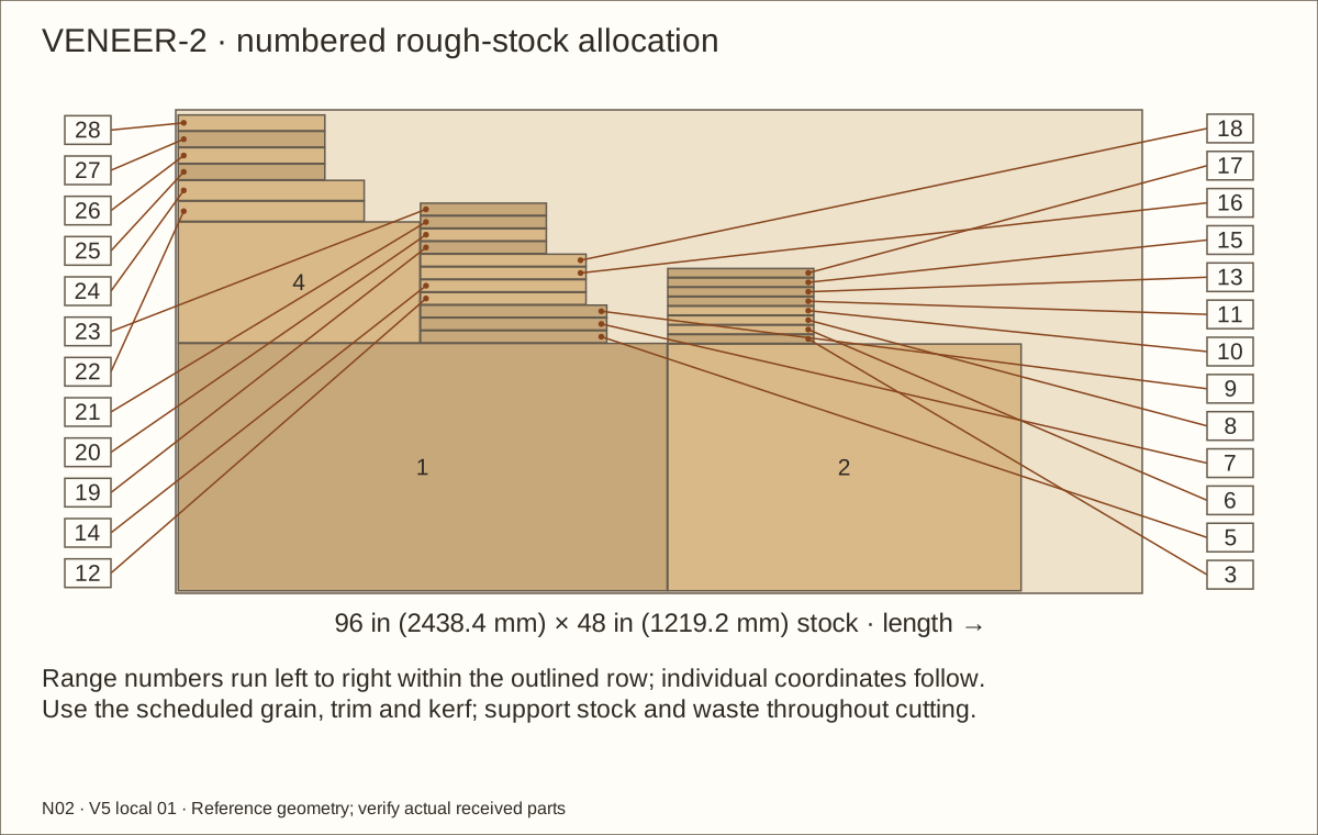
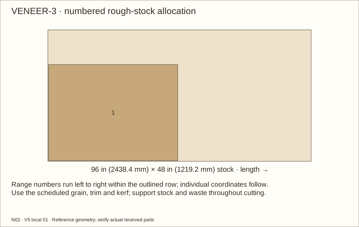
Choose ONE veneer species: three 48 × 96 in (1219.2 × 2438.4 mm) sheets. Trial stock is included. Resolve receiving holds before dependent work. Product identity checks do not guarantee destination stock or physical fit.
Three trim-tolerant 96 by 48 in (1219.2 mm) stock layouts include 1/8 in (3.18 mm) kerf, edge trim and rough-part allowances. Final floor/roof remain 48 by 24 in (609.6 mm); never shrink the core to save stock.
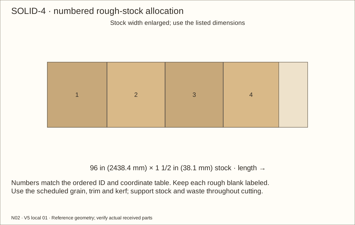
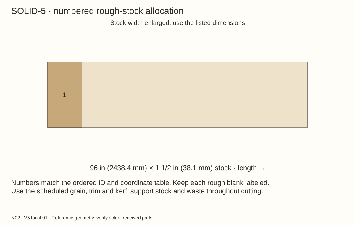
Five 96 in (2438.4 mm) solid-stock allocations include end and crosscut allowance for this build. Preserve the full measured 1 1/2 in (38.1 mm) square reference section; exact IDs and lengths are in the cutting layouts.
Materials and hardware · continued
Choose ONE veneer species: three 48 × 96 in (1219.2 × 2438.4 mm) sheets. Trial stock is included. Resolve receiving holds before dependent work. Product identity checks do not guarantee destination stock or physical fit.
30-004-062-012-036 Needed 1; 1 per package; buy 1 package(s)
Four 17.16375 in (435.96 mm) × 0.28 in (7.11 mm) × 1/16 in (1.59 mm) reference cushions. Accepted contact bond to jamb web; no screw tabs across tracks.
Bond only the named bare-wood interfaces; never use as a basin seal.
Materials and hardware · continued
Choose ONE veneer species: three 48 × 96 in (1219.2 × 2438.4 mm) sheets. Trial stock is included. Resolve receiving holds before dependent work. Product identity checks do not guarantee destination stock or physical fit.
284473-7482 Needed 5; 2 per package; buy 3 package(s)
219.30 square feet (20.37 square metres) planned. 5 US-quart cans (0.946 L each), sold as two-can packs; Separate removable liner; extra coats or balancing layers require recalculation.
Exact screw count comes from the station schedule; purchased packs include spare screws.
Materials and hardware · continued
Choose ONE veneer species: three 48 × 96 in (1219.2 × 2438.4 mm) sheets. Trial stock is included. Resolve receiving holds before dependent work. Product identity checks do not guarantee destination stock or physical fit.
D2203A48 Needed 1; 1 per package; buy 1 package(s)
One D2203A48 precut kit: 48 in (1219.2 mm) D602/D603 rails, two D610 shoes, four D650 nylon wheels and four D652 guides. Confirm usable shoe lengths and received inventory before cutting. Separate D603A stock supplies jambs. Cosmetic caps omitted subject to accepted retention and deburred ends.
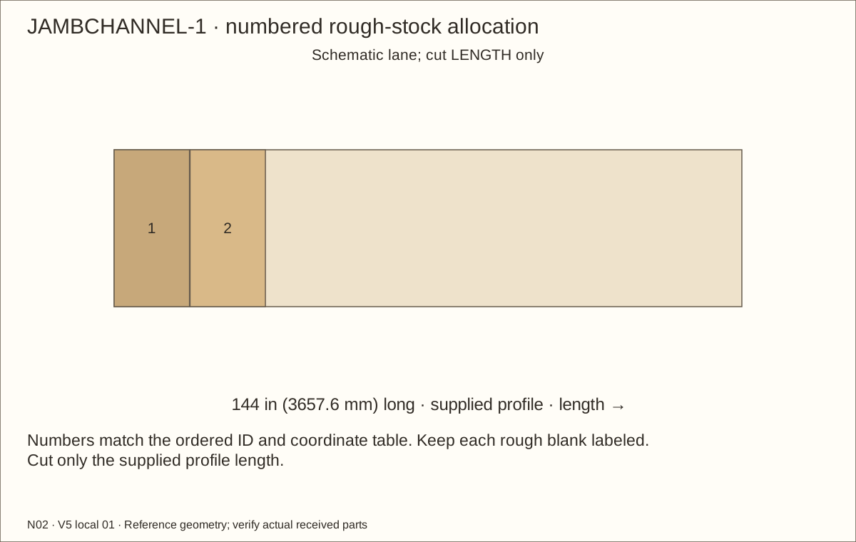
One 144 in (3657.6 mm) D603A length supplies both 17.16375 in (435.96 mm) reference jambs with kerf and spare. Ask supplier for shipping cuts that preserve both blanks.
Materials and hardware · continued
Choose ONE veneer species: three 48 × 96 in (1219.2 × 2438.4 mm) sheets. Trial stock is included. Resolve receiving holds before dependent work. Product identity checks do not guarantee destination stock or physical fit.
HOLD: kit recommendation for 6 mm glass conflicts with current GC728C thickness listing. Supplier must confirm exact vinyl for measured glass and shoe. Do not substitute or force the glass.
Published overlap range 3/4–3 3/8 in (85.73 mm); this design targets 1 1/2 in (38.1 mm). Remove the lock body for sliding. Separate anti-lift inserts remain installed.
Two installed; current US minimum order ten each leaves eight spare. Confirm supplier preparation, adhesive dwell and availability.
Materials and hardware · continued
Choose ONE veneer species: three 48 × 96 in (1219.2 × 2438.4 mm) sheets. Trial stock is included. Resolve receiving holds before dependent work. Product identity checks do not guarantee destination stock or physical fit.
806891 Needed 34; 12 per package; buy 3 package(s)
Thirty-four installed: eight lower rail, eight upper channel, six jamb and twelve anti-lift screws. Three 12-packs provide two spares. Supplier-approved thin-web countersink and flush trial required; do not drill the upper centre divider.
6 mm clear, polished edges; no holes Needed 2; 1 per package; buy 2 package(s)
Two 6 mm tempered reference panes. Size after actual tracks, cushions, vinyl, guides, finish and anti-lift acceptance; no glass order from this reference.
LINER · Aquascape 45 mil ethylene propylene diene monomer (EPDM) boxed liner, 8′ × 10′ Direct product listing
85009 Needed 1; 1 per package; buy 1 package(s)
One 8 × 10-foot 45 mil (0.045 in / 1.14 mm) EPDM sheet supplies the 84 in (2133.6 mm) × 58 in (1473.2 mm) rough blank plus generous offcuts. No seams or corner cuts below the clamp line.
Materials and hardware · continued
Choose ONE veneer species: three 48 × 96 in (1219.2 × 2438.4 mm) sheets. Trial stock is included. Resolve receiving holds before dependent work. Product identity checks do not guarantee destination stock or physical fit.
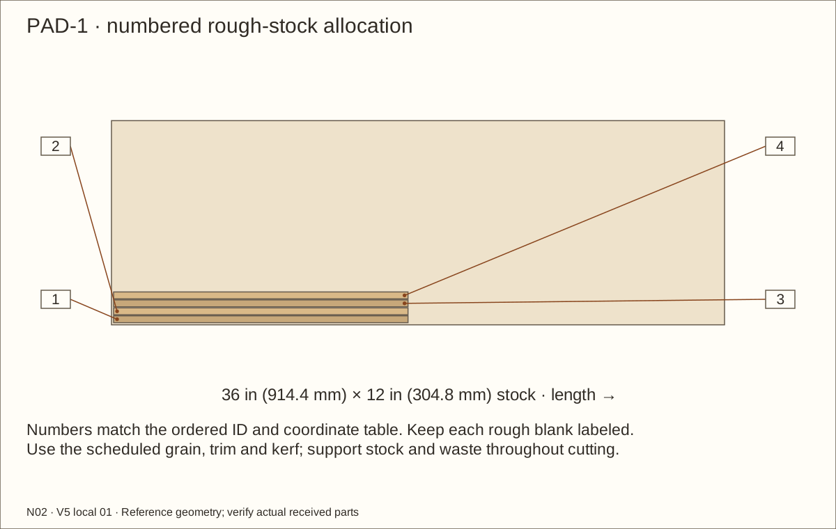
One 5 × 10-foot sheet supplies a 84 in (2133.6 mm) × 58 in (1473.2 mm) reference blank. Measure its actual compressed thickness; protect every contact surface, cleat edge and post. Do not glue it to the liner.
HDPE · Polymershapes smooth black high-density polyethylene (HDPE) sheet Direct product listing
51962104 Needed 1; 1 per package; buy 1 package(s)
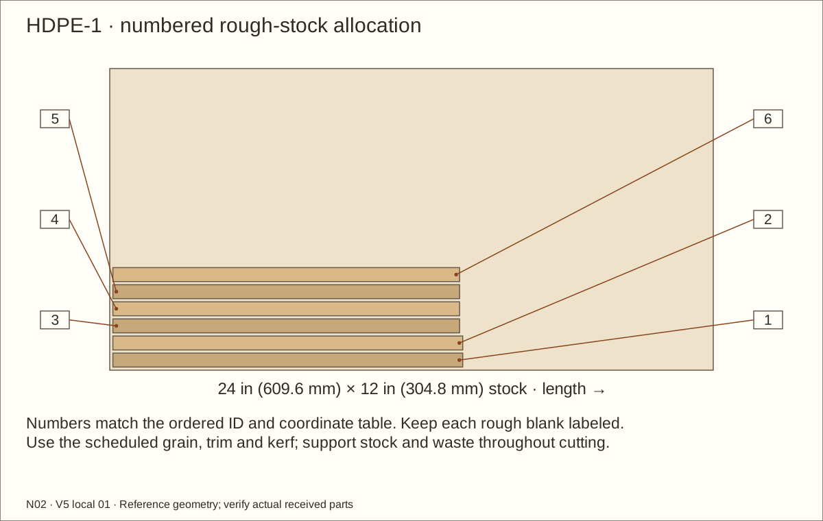
Six removable inserts, three per lane, from one 24 x 12 in (304.8 mm) sheet. Preserve internal joints and outer service gaps; test positive guide retention and the supported removal sequence.
Three exterior flush screws per retainer post; 5/32 in (3.97 mm) hex drive, 82-degree seat. Length includes flat head.
Materials and hardware · continued
Choose ONE veneer species: three 48 × 96 in (1219.2 × 2438.4 mm) sheets. Trial stock is included. Resolve receiving holds before dependent work. Product identity checks do not guarantee destination stock or physical fit.
One inside each recessed post under locknut. 5/8 in (15.88 mm) outside and 9/32 in (7.14 mm) inside diameters; receive thickness at most 1/16 in (1.59 mm) for this reference stack.
One inside each recessed post. Listed height .298-.328″; two full threads beyond nylon, entire tail below post face. Hand-tighten to avoid stainless galling; never force seized threads.
4 × 8 ft, selected species, 3M PSA; confirm exact configuration Needed 3; 1 per package; buy 3 package(s) Choose one species only
Full exterior faces, roof, edges, reveals and trial. Written balance, substrate/finish and service-environment acceptance required.
Materials and hardware · continued
Choose ONE veneer species: three 48 × 96 in (1219.2 × 2438.4 mm) sheets. Trial stock is included. Resolve receiving holds before dependent work. Product identity checks do not guarantee destination stock or physical fit.
Four neoprene jamb cushions only, 0.267 square feet two-face area plus trial. Written anodized aluminium/neoprene acceptance and seven-day sample cure. Never use on liner, glass or HDPE.
Cut list
Cut list
One of each named ID. Rough blanks include scheduled trimming. Thickness is the prepared blank: plane 3/4-inch (19.05 mm) pine to 3/8 inch (9.53 mm) before ripping thin strips. Fit the listed anti-lift inserts from 1/2-inch (12.7 mm) HDPE stock to their accepted installed thickness. Reference finished sizes need actual-material fitting. V-parts represent the complete cured veneer stack. Hardware profiles use schematic stock lanes: never rip them to the lane width. Glass is a fabricator order after accepted field sizing.
Part
Rough length × width × prepared thickness
Reference finished size
P01 · Floor
48 1/8 in (1222.38 mm) × 24 1/16 in (611.19 mm) × 45/64 in (17.86 mm)
48 in (1219.2 mm) × 24 in (609.6 mm) × 45/64 in (17.86 mm)
P02 · Removable roof
48 1/8 in (1222.38 mm) × 24 1/16 in (611.19 mm) × 45/64 in (17.86 mm)
48 in (1219.2 mm) × 24 in (609.6 mm) × 45/64 in (17.86 mm)
P03L · L wall
24 1/8 in (612.78 mm) × 34 21/32 in (880.27 mm) × 45/64 in (17.86 mm)
24 in (609.6 mm) × 34 19/32 in (878.68 mm) × 45/64 in (17.86 mm)
P03R · R wall
24 1/8 in (612.78 mm) × 34 21/32 in (880.27 mm) × 45/64 in (17.86 mm)
24 in (609.6 mm) × 34 19/32 in (878.68 mm) × 45/64 in (17.86 mm)
P04 · Back
46 23/32 in (1186.66 mm) × 34 21/32 in (880.27 mm) × 45/64 in (17.86 mm)
46 19/32 in (1183.48 mm) × 34 19/32 in (878.68 mm) × 45/64 in (17.86 mm)
RB1 · Laminated substrate retaining board
46 23/32 in (1186.66 mm) × 14 3/16 in (360.36 mm) × 45/64 in (17.86 mm)
46 19/32 in (1183.48 mm) × 14 1/8 in (358.78 mm) × 45/64 in (17.86 mm)
RB2 · Laminated substrate retaining board
46 23/32 in (1186.66 mm) × 14 3/16 in (360.36 mm) × 45/64 in (17.86 mm)
46 19/32 in (1183.48 mm) × 14 1/8 in (358.78 mm) × 45/64 in (17.86 mm)
RB3 · Laminated substrate retaining board
46 23/32 in (1186.66 mm) × 14 3/16 in (360.36 mm) × 45/64 in (17.86 mm)
46 19/32 in (1183.48 mm) × 14 1/8 in (358.78 mm) × 45/64 in (17.86 mm)
F0L · L jamb layer
20 19/32 in (523.08 mm) × 2 9/16 in (65.09 mm) × 3/4 in (19.05 mm)
20 15/32 in (519.91 mm) × 2 1/2 in (63.5 mm) × 3/4 in (19.05 mm)
F0R · R jamb layer
20 19/32 in (523.08 mm) × 2 9/16 in (65.09 mm) × 3/4 in (19.05 mm)
20 15/32 in (519.91 mm) × 2 1/2 in (63.5 mm) × 3/4 in (19.05 mm)
Cut list · continued
One of each named ID. Rough blanks include scheduled trimming. Thickness is the prepared blank: plane 3/4-inch (19.05 mm) pine to 3/8 inch (9.53 mm) before ripping thin strips. Fit the listed anti-lift inserts from 1/2-inch (12.7 mm) HDPE stock to their accepted installed thickness. Reference finished sizes need actual-material fitting. V-parts represent the complete cured veneer stack. Hardware profiles use schematic stock lanes: never rip them to the lane width. Glass is a fabricator order after accepted field sizing.
Part
Rough length × width × prepared thickness
Reference finished size
F0T · Header layer
41 23/32 in (1059.66 mm) × 2 9/16 in (65.09 mm) × 3/4 in (19.05 mm)
41 19/32 in (1056.48 mm) × 2 1/2 in (63.5 mm) × 3/4 in (19.05 mm)
F1L · L jamb layer
18 3/32 in (459.58 mm) × 2 9/16 in (65.09 mm) × 3/4 in (19.05 mm)
17 31/32 in (456.41 mm) × 2 1/2 in (63.5 mm) × 3/4 in (19.05 mm)
F1R · R jamb layer
18 3/32 in (459.58 mm) × 2 9/16 in (65.09 mm) × 3/4 in (19.05 mm)
17 31/32 in (456.41 mm) × 2 1/2 in (63.5 mm) × 3/4 in (19.05 mm)
F1T · Header layer
46 23/32 in (1186.66 mm) × 2 9/16 in (65.09 mm) × 3/4 in (19.05 mm)
46 19/32 in (1183.48 mm) × 2 1/2 in (63.5 mm) × 3/4 in (19.05 mm)
CLB · L bottom cleat
21 5/16 in (541.34 mm) × 1 1/2 in (38.1 mm) × 1 1/2 in (38.1 mm)
21 3/16 in (538.16 mm) × 1 1/2 in (38.1 mm) × 1 1/2 in (38.1 mm)
CLU · L rear upright
31 23/32 in (805.66 mm) × 1 1/2 in (38.1 mm) × 1 1/2 in (38.1 mm)
31 19/32 in (802.48 mm) × 1 1/2 in (38.1 mm) × 1 1/2 in (38.1 mm)
CLT · L upper cleat
21 59/64 in (556.82 mm) × 1 1/2 in (38.1 mm) × 1 1/2 in (38.1 mm)
21 51/64 in (553.64 mm) × 1 1/2 in (38.1 mm) × 1 1/2 in (38.1 mm)
CRB · R bottom cleat
21 5/16 in (541.34 mm) × 1 1/2 in (38.1 mm) × 1 1/2 in (38.1 mm)
21 3/16 in (538.16 mm) × 1 1/2 in (38.1 mm) × 1 1/2 in (38.1 mm)
CRU · R rear upright
31 23/32 in (805.66 mm) × 1 1/2 in (38.1 mm) × 1 1/2 in (38.1 mm)
31 19/32 in (802.48 mm) × 1 1/2 in (38.1 mm) × 1 1/2 in (38.1 mm)
CRT · R upper cleat
21 59/64 in (556.82 mm) × 1 1/2 in (38.1 mm) × 1 1/2 in (38.1 mm)
21 51/64 in (553.64 mm) × 1 1/2 in (38.1 mm) × 1 1/2 in (38.1 mm)
Cut list · continued
One of each named ID. Rough blanks include scheduled trimming. Thickness is the prepared blank: plane 3/4-inch (19.05 mm) pine to 3/8 inch (9.53 mm) before ripping thin strips. Fit the listed anti-lift inserts from 1/2-inch (12.7 mm) HDPE stock to their accepted installed thickness. Reference finished sizes need actual-material fitting. V-parts represent the complete cured veneer stack. Hardware profiles use schematic stock lanes: never rip them to the lane width. Glass is a fabricator order after accepted field sizing.
Part
Rough length × width × prepared thickness
Reference finished size
CF · Front floor cleat
43 23/32 in (1110.46 mm) × 1 1/2 in (38.1 mm) × 1 1/2 in (38.1 mm)
43 19/32 in (1107.28 mm) × 1 1/2 in (38.1 mm) × 1 1/2 in (38.1 mm)
CB · Back floor cleat
43 23/32 in (1110.46 mm) × 1 1/2 in (38.1 mm) × 1 1/2 in (38.1 mm)
43 19/32 in (1107.28 mm) × 1 1/2 in (38.1 mm) × 1 1/2 in (38.1 mm)
CT · Back upper cleat
43 23/32 in (1110.46 mm) × 1 1/2 in (38.1 mm) × 1 1/2 in (38.1 mm)
43 19/32 in (1107.28 mm) × 1 1/2 in (38.1 mm) × 1 1/2 in (38.1 mm)
CR · Roof centre rib
20 27/64 in (518.72 mm) × 1 1/2 in (38.1 mm) × 1 1/2 in (38.1 mm)
20 19/64 in (515.54 mm) × 1 1/2 in (38.1 mm) × 1 1/2 in (38.1 mm)
ML · L ventilation mesh
13 in (330.2 mm) × 4 in (101.6 mm) × 0.082 in (2.08 mm)
13 in (330.2 mm) × 4 in (101.6 mm) × 0.082 in (2.08 mm)
VLB · Vent capture strip
14 1/8 in (358.78 mm) × 1 1/16 in (26.99 mm) × 3/8 in (9.53 mm)
14 in (355.6 mm) × 1 in (25.4 mm) × 3/8 in (9.53 mm)
VLT · Vent capture strip
14 1/8 in (358.78 mm) × 1 1/16 in (26.99 mm) × 3/8 in (9.53 mm)
14 in (355.6 mm) × 1 in (25.4 mm) × 3/8 in (9.53 mm)
VLF · Vent end strip
3 1/8 in (79.38 mm) × 1 1/16 in (26.99 mm) × 3/8 in (9.53 mm)
3 in (76.2 mm) × 1 in (25.4 mm) × 3/8 in (9.53 mm)
VLA · Vent end strip
3 1/8 in (79.38 mm) × 1 1/16 in (26.99 mm) × 3/8 in (9.53 mm)
3 in (76.2 mm) × 1 in (25.4 mm) × 3/8 in (9.53 mm)
MR · R ventilation mesh
13 in (330.2 mm) × 4 in (101.6 mm) × 0.082 in (2.08 mm)
13 in (330.2 mm) × 4 in (101.6 mm) × 0.082 in (2.08 mm)
Cut list · continued
One of each named ID. Rough blanks include scheduled trimming. Thickness is the prepared blank: plane 3/4-inch (19.05 mm) pine to 3/8 inch (9.53 mm) before ripping thin strips. Fit the listed anti-lift inserts from 1/2-inch (12.7 mm) HDPE stock to their accepted installed thickness. Reference finished sizes need actual-material fitting. V-parts represent the complete cured veneer stack. Hardware profiles use schematic stock lanes: never rip them to the lane width. Glass is a fabricator order after accepted field sizing.
Part
Rough length × width × prepared thickness
Reference finished size
VRB · Vent capture strip
14 1/8 in (358.78 mm) × 1 1/16 in (26.99 mm) × 3/8 in (9.53 mm)
14 in (355.6 mm) × 1 in (25.4 mm) × 3/8 in (9.53 mm)
VRT · Vent capture strip
14 1/8 in (358.78 mm) × 1 1/16 in (26.99 mm) × 3/8 in (9.53 mm)
14 in (355.6 mm) × 1 in (25.4 mm) × 3/8 in (9.53 mm)
VRF · Vent end strip
3 1/8 in (79.38 mm) × 1 1/16 in (26.99 mm) × 3/8 in (9.53 mm)
3 in (76.2 mm) × 1 in (25.4 mm) × 3/8 in (9.53 mm)
VRA · Vent end strip
3 1/8 in (79.38 mm) × 1 1/16 in (26.99 mm) × 3/8 in (9.53 mm)
3 in (76.2 mm) × 1 in (25.4 mm) × 3/8 in (9.53 mm)
MTL · Roof mesh
19 in (482.6 mm) × 17 in (431.8 mm) × 0.082 in (2.08 mm)
19 in (482.6 mm) × 17 in (431.8 mm) × 0.082 in (2.08 mm)
RTLF · Roof mesh capture strip
20 1/8 in (511.18 mm) × 1 1/16 in (26.99 mm) × 3/8 in (9.53 mm)
20 in (508 mm) × 1 in (25.4 mm) × 3/8 in (9.53 mm)
RTLA · Roof mesh capture strip
20 1/8 in (511.18 mm) × 1 1/16 in (26.99 mm) × 3/8 in (9.53 mm)
20 in (508 mm) × 1 in (25.4 mm) × 3/8 in (9.53 mm)
RTLL · Roof mesh side strip
16 1/8 in (409.58 mm) × 1 1/16 in (26.99 mm) × 3/8 in (9.53 mm)
16 in (406.4 mm) × 1 in (25.4 mm) × 3/8 in (9.53 mm)
RTLR · Roof mesh side strip
16 1/8 in (409.58 mm) × 1 1/16 in (26.99 mm) × 3/8 in (9.53 mm)
16 in (406.4 mm) × 1 in (25.4 mm) × 3/8 in (9.53 mm)
MTR · Roof mesh
19 in (482.6 mm) × 17 in (431.8 mm) × 0.082 in (2.08 mm)
19 in (482.6 mm) × 17 in (431.8 mm) × 0.082 in (2.08 mm)
Cut list · continued
One of each named ID. Rough blanks include scheduled trimming. Thickness is the prepared blank: plane 3/4-inch (19.05 mm) pine to 3/8 inch (9.53 mm) before ripping thin strips. Fit the listed anti-lift inserts from 1/2-inch (12.7 mm) HDPE stock to their accepted installed thickness. Reference finished sizes need actual-material fitting. V-parts represent the complete cured veneer stack. Hardware profiles use schematic stock lanes: never rip them to the lane width. Glass is a fabricator order after accepted field sizing.
Part
Rough length × width × prepared thickness
Reference finished size
RTRF · Roof mesh capture strip
20 1/8 in (511.18 mm) × 1 1/16 in (26.99 mm) × 3/8 in (9.53 mm)
20 in (508 mm) × 1 in (25.4 mm) × 3/8 in (9.53 mm)
RTRA · Roof mesh capture strip
20 1/8 in (511.18 mm) × 1 1/16 in (26.99 mm) × 3/8 in (9.53 mm)
20 in (508 mm) × 1 in (25.4 mm) × 3/8 in (9.53 mm)
RTRL · Roof mesh side strip
16 1/8 in (409.58 mm) × 1 1/16 in (26.99 mm) × 3/8 in (9.53 mm)
16 in (406.4 mm) × 1 in (25.4 mm) × 3/8 in (9.53 mm)
RTRR · Roof mesh side strip
16 1/8 in (409.58 mm) × 1 1/16 in (26.99 mm) × 3/8 in (9.53 mm)
16 in (406.4 mm) × 1 in (25.4 mm) × 3/8 in (9.53 mm)
LCL · Liner side clamp
17.1525 in (435.67 mm) × 9/16 in (14.29 mm) × 3/8 in (9.53 mm)
17.0275 in (432.5 mm) × 1/2 in (12.7 mm) × 3/8 in (9.53 mm)
LCR · Liner side clamp
17.1525 in (435.67 mm) × 9/16 in (14.29 mm) × 3/8 in (9.53 mm)
17.0275 in (432.5 mm) × 1/2 in (12.7 mm) × 3/8 in (9.53 mm)
LCF · Liner front clamp
42.80875 in (1087.34 mm) × 9/16 in (14.29 mm) × 3/8 in (9.53 mm)
42.68375 in (1084.17 mm) × 1/2 in (12.7 mm) × 3/8 in (9.53 mm)
LCBL · Liner back clamp beside centre upright
20.261875 in (514.65 mm) × 9/16 in (14.29 mm) × 3/8 in (9.53 mm)
20.136875 in (511.48 mm) × 1/2 in (12.7 mm) × 3/8 in (9.53 mm)
LCBR · Liner back clamp beside centre upright
20.261875 in (514.65 mm) × 9/16 in (14.29 mm) × 3/8 in (9.53 mm)
20.136875 in (511.48 mm) × 1/2 in (12.7 mm) × 3/8 in (9.53 mm)
LCM · Liner centre-post face clamp
1 5/8 in (41.28 mm) × 9/16 in (14.29 mm) × 3/8 in (9.53 mm)
1 1/2 in (38.1 mm) × 1/2 in (12.7 mm) × 3/8 in (9.53 mm)
Cut list · continued
One of each named ID. Rough blanks include scheduled trimming. Thickness is the prepared blank: plane 3/4-inch (19.05 mm) pine to 3/8 inch (9.53 mm) before ripping thin strips. Fit the listed anti-lift inserts from 1/2-inch (12.7 mm) HDPE stock to their accepted installed thickness. Reference finished sizes need actual-material fitting. V-parts represent the complete cured veneer stack. Hardware profiles use schematic stock lanes: never rip them to the lane width. Glass is a fabricator order after accepted field sizing.
Part
Rough length × width × prepared thickness
Reference finished size
LCQL · Liner front-post face clamp
1 1/2 in (38.1 mm) × 9/16 in (14.29 mm) × 3/8 in (9.53 mm)
1 3/8 in (34.93 mm) × 1/2 in (12.7 mm) × 3/8 in (9.53 mm)
LCQR · Liner front-post face clamp
1 1/2 in (38.1 mm) × 9/16 in (14.29 mm) × 3/8 in (9.53 mm)
1 3/8 in (34.93 mm) × 1/2 in (12.7 mm) × 3/8 in (9.53 mm)
LCPL · Liner rear-post face clamp
1 1/2 in (38.1 mm) × 9/16 in (14.29 mm) × 3/8 in (9.53 mm)
1 3/8 in (34.93 mm) × 1/2 in (12.7 mm) × 3/8 in (9.53 mm)
LCPR · Liner rear-post face clamp
1 1/2 in (38.1 mm) × 9/16 in (14.29 mm) × 3/8 in (9.53 mm)
1 3/8 in (34.93 mm) × 1/2 in (12.7 mm) × 3/8 in (9.53 mm)
CFL · Front retainer post
12 3/4 in (323.85 mm) × 1 1/2 in (38.1 mm) × 1 1/2 in (38.1 mm)
12 5/8 in (320.68 mm) × 1 1/2 in (38.1 mm) × 1 1/2 in (38.1 mm)
CFR · Front retainer post
12 3/4 in (323.85 mm) × 1 1/2 in (38.1 mm) × 1 1/2 in (38.1 mm)
12 5/8 in (320.68 mm) × 1 1/2 in (38.1 mm) × 1 1/2 in (38.1 mm)
CM · Centre back upright
31 23/32 in (805.66 mm) × 1 1/2 in (38.1 mm) × 1 1/2 in (38.1 mm)
31 19/32 in (802.48 mm) × 1 1/2 in (38.1 mm) × 1 1/2 in (38.1 mm)
V-floor-under · Veneer · floor-under
48.561 in (1233.45 mm) × 24.561 in (623.85 mm) × 0.0305 in (0.77 mm)
48.061 in (1220.75 mm) × 24.061 in (611.15 mm) × 0.0305 in (0.77 mm)
V-roof-top · Veneer · roof-top
48.561 in (1233.45 mm) × 24.561 in (623.85 mm) × 0.0305 in (0.77 mm)
48.061 in (1220.75 mm) × 24.061 in (611.15 mm) × 0.0305 in (0.77 mm)
V-P01-front · Veneer · P01-front
48.561 in (1233.45 mm) × 1 13/64 in (30.56 mm) × 0.0305 in (0.77 mm)
48.061 in (1220.75 mm) × 45/64 in (17.86 mm) × 0.0305 in (0.77 mm)
Cut list · continued
One of each named ID. Rough blanks include scheduled trimming. Thickness is the prepared blank: plane 3/4-inch (19.05 mm) pine to 3/8 inch (9.53 mm) before ripping thin strips. Fit the listed anti-lift inserts from 1/2-inch (12.7 mm) HDPE stock to their accepted installed thickness. Reference finished sizes need actual-material fitting. V-parts represent the complete cured veneer stack. Hardware profiles use schematic stock lanes: never rip them to the lane width. Glass is a fabricator order after accepted field sizing.
Part
Rough length × width × prepared thickness
Reference finished size
V-P01-back · Veneer · P01-back
48.561 in (1233.45 mm) × 1 13/64 in (30.56 mm) × 0.0305 in (0.77 mm)
48.061 in (1220.75 mm) × 45/64 in (17.86 mm) × 0.0305 in (0.77 mm)
V-P01-left · Veneer · P01-left
24 1/2 in (622.3 mm) × 1 13/64 in (30.56 mm) × 0.0305 in (0.77 mm)
24 in (609.6 mm) × 45/64 in (17.86 mm) × 0.0305 in (0.77 mm)
V-P01-right · Veneer · P01-right
24 1/2 in (622.3 mm) × 1 13/64 in (30.56 mm) × 0.0305 in (0.77 mm)
24 in (609.6 mm) × 45/64 in (17.86 mm) × 0.0305 in (0.77 mm)
V-P02-front · Veneer · P02-front
48.561 in (1233.45 mm) × 1 13/64 in (30.56 mm) × 0.0305 in (0.77 mm)
48.061 in (1220.75 mm) × 45/64 in (17.86 mm) × 0.0305 in (0.77 mm)
V-P02-back · Veneer · P02-back
48.561 in (1233.45 mm) × 1 13/64 in (30.56 mm) × 0.0305 in (0.77 mm)
48.061 in (1220.75 mm) × 45/64 in (17.86 mm) × 0.0305 in (0.77 mm)
V-P02-left · Veneer · P02-left
24 1/2 in (622.3 mm) × 1 13/64 in (30.56 mm) × 0.0305 in (0.77 mm)
24 in (609.6 mm) × 45/64 in (17.86 mm) × 0.0305 in (0.77 mm)
V-P02-right · Veneer · P02-right
24 1/2 in (622.3 mm) × 1 13/64 in (30.56 mm) × 0.0305 in (0.77 mm)
24 in (609.6 mm) × 45/64 in (17.86 mm) × 0.0305 in (0.77 mm)
V-P03L-face · Veneer · P03L-face
35 3/32 in (891.38 mm) × 24 1/2 in (622.3 mm) × 0.0305 in (0.77 mm)
34 19/32 in (878.68 mm) × 24 in (609.6 mm) × 0.0305 in (0.77 mm)
V-P03L-front · Veneer · P03L-front
35 3/32 in (891.38 mm) × 1.233625 in (31.33 mm) × 0.0305 in (0.77 mm)
34 19/32 in (878.68 mm) × 0.733625 in (18.63 mm) × 0.0305 in (0.77 mm)
V-P03L-back · Veneer · P03L-back
35 3/32 in (891.38 mm) × 1.233625 in (31.33 mm) × 0.0305 in (0.77 mm)
34 19/32 in (878.68 mm) × 0.733625 in (18.63 mm) × 0.0305 in (0.77 mm)
Cut list · continued
One of each named ID. Rough blanks include scheduled trimming. Thickness is the prepared blank: plane 3/4-inch (19.05 mm) pine to 3/8 inch (9.53 mm) before ripping thin strips. Fit the listed anti-lift inserts from 1/2-inch (12.7 mm) HDPE stock to their accepted installed thickness. Reference finished sizes need actual-material fitting. V-parts represent the complete cured veneer stack. Hardware profiles use schematic stock lanes: never rip them to the lane width. Glass is a fabricator order after accepted field sizing.
Part
Rough length × width × prepared thickness
Reference finished size
V-P03L-vent-near · Veneer · P03L-vent-near
3.439 in (87.35 mm) × 1 13/64 in (30.56 mm) × 0.0305 in (0.77 mm)
2.939 in (74.65 mm) × 45/64 in (17.86 mm) × 0.0305 in (0.77 mm)
V-P03L-vent-far · Veneer · P03L-vent-far
3.439 in (87.35 mm) × 1 13/64 in (30.56 mm) × 0.0305 in (0.77 mm)
2.939 in (74.65 mm) × 45/64 in (17.86 mm) × 0.0305 in (0.77 mm)
V-P03L-vent-bottom · Veneer · P03L-vent-bottom
12 1/2 in (317.5 mm) × 1 13/64 in (30.56 mm) × 0.0305 in (0.77 mm)
12 in (304.8 mm) × 45/64 in (17.86 mm) × 0.0305 in (0.77 mm)
V-P03L-vent-top · Veneer · P03L-vent-top
12 1/2 in (317.5 mm) × 1 13/64 in (30.56 mm) × 0.0305 in (0.77 mm)
12 in (304.8 mm) × 45/64 in (17.86 mm) × 0.0305 in (0.77 mm)
V-P03R-face · Veneer · P03R-face
35 3/32 in (891.38 mm) × 24 1/2 in (622.3 mm) × 0.0305 in (0.77 mm)
34 19/32 in (878.68 mm) × 24 in (609.6 mm) × 0.0305 in (0.77 mm)
V-P03R-front · Veneer · P03R-front
35 3/32 in (891.38 mm) × 1.233625 in (31.33 mm) × 0.0305 in (0.77 mm)
34 19/32 in (878.68 mm) × 0.733625 in (18.63 mm) × 0.0305 in (0.77 mm)
V-P03R-back · Veneer · P03R-back
35 3/32 in (891.38 mm) × 1.233625 in (31.33 mm) × 0.0305 in (0.77 mm)
34 19/32 in (878.68 mm) × 0.733625 in (18.63 mm) × 0.0305 in (0.77 mm)
V-P03R-vent-near · Veneer · P03R-vent-near
3.439 in (87.35 mm) × 1 13/64 in (30.56 mm) × 0.0305 in (0.77 mm)
2.939 in (74.65 mm) × 45/64 in (17.86 mm) × 0.0305 in (0.77 mm)
V-P03R-vent-far · Veneer · P03R-vent-far
3.439 in (87.35 mm) × 1 13/64 in (30.56 mm) × 0.0305 in (0.77 mm)
2.939 in (74.65 mm) × 45/64 in (17.86 mm) × 0.0305 in (0.77 mm)
V-P03R-vent-bottom · Veneer · P03R-vent-bottom
12 1/2 in (317.5 mm) × 1 13/64 in (30.56 mm) × 0.0305 in (0.77 mm)
12 in (304.8 mm) × 45/64 in (17.86 mm) × 0.0305 in (0.77 mm)
Cut list · continued
One of each named ID. Rough blanks include scheduled trimming. Thickness is the prepared blank: plane 3/4-inch (19.05 mm) pine to 3/8 inch (9.53 mm) before ripping thin strips. Fit the listed anti-lift inserts from 1/2-inch (12.7 mm) HDPE stock to their accepted installed thickness. Reference finished sizes need actual-material fitting. V-parts represent the complete cured veneer stack. Hardware profiles use schematic stock lanes: never rip them to the lane width. Glass is a fabricator order after accepted field sizing.
Part
Rough length × width × prepared thickness
Reference finished size
V-P03R-vent-top · Veneer · P03R-vent-top
12 1/2 in (317.5 mm) × 1 13/64 in (30.56 mm) × 0.0305 in (0.77 mm)
12 in (304.8 mm) × 45/64 in (17.86 mm) × 0.0305 in (0.77 mm)
V-back · Veneer · back
47 3/32 in (1196.18 mm) × 35 3/32 in (891.38 mm) × 0.0305 in (0.77 mm)
46 19/32 in (1183.48 mm) × 34 19/32 in (878.68 mm) × 0.0305 in (0.77 mm)
V-RB1-front · Veneer · RB1-front
47 3/32 in (1196.18 mm) × 14 5/8 in (371.48 mm) × 0.0305 in (0.77 mm)
46 19/32 in (1183.48 mm) × 14 1/8 in (358.78 mm) × 0.0305 in (0.77 mm)
V-F0L-front · Veneer · F0L-front
20 31/32 in (532.61 mm) × 3 in (76.2 mm) × 0.0305 in (0.77 mm)
20 15/32 in (519.91 mm) × 2 1/2 in (63.5 mm) × 0.0305 in (0.77 mm)
V-F0R-front · Veneer · F0R-front
20 31/32 in (532.61 mm) × 3 in (76.2 mm) × 0.0305 in (0.77 mm)
20 15/32 in (519.91 mm) × 2 1/2 in (63.5 mm) × 0.0305 in (0.77 mm)
V-F0T-front · Veneer · F0T-front
42 3/32 in (1069.18 mm) × 3 in (76.2 mm) × 0.0305 in (0.77 mm)
41 19/32 in (1056.48 mm) × 2 1/2 in (63.5 mm) × 0.0305 in (0.77 mm)
V-opening-left · Veneer · opening-left
18 15/32 in (469.11 mm) × 2 in (50.8 mm) × 0.0305 in (0.77 mm)
17 31/32 in (456.41 mm) × 1 1/2 in (38.1 mm) × 0.0305 in (0.77 mm)
V-opening-right · Veneer · opening-right
18 15/32 in (469.11 mm) × 2 in (50.8 mm) × 0.0305 in (0.77 mm)
17 31/32 in (456.41 mm) × 1 1/2 in (38.1 mm) × 0.0305 in (0.77 mm)
V-opening-upper · Veneer · opening-upper
42.03275 in (1067.63 mm) × 2 in (50.8 mm) × 0.0305 in (0.77 mm)
41.53275 in (1054.93 mm) × 1 1/2 in (38.1 mm) × 0.0305 in (0.77 mm)
V-retainer-top · Veneer · retainer-top
42.03275 in (1067.63 mm) × 2 39/64 in (66.28 mm) × 0.0305 in (0.77 mm)
41.53275 in (1054.93 mm) × 2 7/64 in (53.58 mm) × 0.0305 in (0.77 mm)
Cut list · continued
One of each named ID. Rough blanks include scheduled trimming. Thickness is the prepared blank: plane 3/4-inch (19.05 mm) pine to 3/8 inch (9.53 mm) before ripping thin strips. Fit the listed anti-lift inserts from 1/2-inch (12.7 mm) HDPE stock to their accepted installed thickness. Reference finished sizes need actual-material fitting. V-parts represent the complete cured veneer stack. Hardware profiles use schematic stock lanes: never rip them to the lane width. Glass is a fabricator order after accepted field sizing.
Part
Rough length × width × prepared thickness
Reference finished size
V-TL-left · Veneer · TL-left
16.439 in (417.55 mm) × 1 13/64 in (30.56 mm) × 0.0305 in (0.77 mm)
15.939 in (404.85 mm) × 45/64 in (17.86 mm) × 0.0305 in (0.77 mm)
V-TL-right · Veneer · TL-right
16.439 in (417.55 mm) × 1 13/64 in (30.56 mm) × 0.0305 in (0.77 mm)
15.939 in (404.85 mm) × 45/64 in (17.86 mm) × 0.0305 in (0.77 mm)
V-TL-front · Veneer · TL-front
18 1/2 in (469.9 mm) × 1 13/64 in (30.56 mm) × 0.0305 in (0.77 mm)
18 in (457.2 mm) × 45/64 in (17.86 mm) × 0.0305 in (0.77 mm)
V-TL-back · Veneer · TL-back
18 1/2 in (469.9 mm) × 1 13/64 in (30.56 mm) × 0.0305 in (0.77 mm)
18 in (457.2 mm) × 45/64 in (17.86 mm) × 0.0305 in (0.77 mm)
V-TR-left · Veneer · TR-left
16.439 in (417.55 mm) × 1 13/64 in (30.56 mm) × 0.0305 in (0.77 mm)
15.939 in (404.85 mm) × 45/64 in (17.86 mm) × 0.0305 in (0.77 mm)
V-TR-right · Veneer · TR-right
16.439 in (417.55 mm) × 1 13/64 in (30.56 mm) × 0.0305 in (0.77 mm)
15.939 in (404.85 mm) × 45/64 in (17.86 mm) × 0.0305 in (0.77 mm)
V-TR-front · Veneer · TR-front
18 1/2 in (469.9 mm) × 1 13/64 in (30.56 mm) × 0.0305 in (0.77 mm)
18 in (457.2 mm) × 45/64 in (17.86 mm) × 0.0305 in (0.77 mm)
V-TR-back · Veneer · TR-back
18 1/2 in (469.9 mm) × 1 13/64 in (30.56 mm) × 0.0305 in (0.77 mm)
18 in (457.2 mm) × 45/64 in (17.86 mm) × 0.0305 in (0.77 mm)
V-VLB-outer · Veneer · VLB-outer
14.561 in (369.85 mm) × 1.561 in (39.65 mm) × 0.0305 in (0.77 mm)
14.061 in (357.15 mm) × 1.061 in (26.95 mm) × 0.0305 in (0.77 mm)
V-VLB-low · Veneer · VLB-low
14 1/2 in (368.3 mm) × 7/8 in (22.23 mm) × 0.0305 in (0.77 mm)
14 in (355.6 mm) × 3/8 in (9.53 mm) × 0.0305 in (0.77 mm)
Cut list · continued
One of each named ID. Rough blanks include scheduled trimming. Thickness is the prepared blank: plane 3/4-inch (19.05 mm) pine to 3/8 inch (9.53 mm) before ripping thin strips. Fit the listed anti-lift inserts from 1/2-inch (12.7 mm) HDPE stock to their accepted installed thickness. Reference finished sizes need actual-material fitting. V-parts represent the complete cured veneer stack. Hardware profiles use schematic stock lanes: never rip them to the lane width. Glass is a fabricator order after accepted field sizing.
Part
Rough length × width × prepared thickness
Reference finished size
V-VLB-high · Veneer · VLB-high
14 1/2 in (368.3 mm) × 7/8 in (22.23 mm) × 0.0305 in (0.77 mm)
12 in (304.8 mm) × 3/8 in (9.53 mm) × 0.0305 in (0.77 mm)
V-VLB-near · Veneer · VLB-near
1.561 in (39.65 mm) × 7/8 in (22.23 mm) × 0.0305 in (0.77 mm)
1.061 in (26.95 mm) × 3/8 in (9.53 mm) × 0.0305 in (0.77 mm)
V-VLB-far · Veneer · VLB-far
1.561 in (39.65 mm) × 7/8 in (22.23 mm) × 0.0305 in (0.77 mm)
1.061 in (26.95 mm) × 3/8 in (9.53 mm) × 0.0305 in (0.77 mm)
V-VLT-outer · Veneer · VLT-outer
14.561 in (369.85 mm) × 1.561 in (39.65 mm) × 0.0305 in (0.77 mm)
14.061 in (357.15 mm) × 1.061 in (26.95 mm) × 0.0305 in (0.77 mm)
V-VLT-low · Veneer · VLT-low
14 1/2 in (368.3 mm) × 7/8 in (22.23 mm) × 0.0305 in (0.77 mm)
12 in (304.8 mm) × 3/8 in (9.53 mm) × 0.0305 in (0.77 mm)
V-VLT-high · Veneer · VLT-high
14 1/2 in (368.3 mm) × 7/8 in (22.23 mm) × 0.0305 in (0.77 mm)
14 in (355.6 mm) × 3/8 in (9.53 mm) × 0.0305 in (0.77 mm)
V-VLT-near · Veneer · VLT-near
1.561 in (39.65 mm) × 7/8 in (22.23 mm) × 0.0305 in (0.77 mm)
1.061 in (26.95 mm) × 3/8 in (9.53 mm) × 0.0305 in (0.77 mm)
V-VLT-far · Veneer · VLT-far
1.561 in (39.65 mm) × 7/8 in (22.23 mm) × 0.0305 in (0.77 mm)
1.061 in (26.95 mm) × 3/8 in (9.53 mm) × 0.0305 in (0.77 mm)
V-VLF-outer · Veneer · VLF-outer
3.439 in (87.35 mm) × 1.561 in (39.65 mm) × 0.0305 in (0.77 mm)
2.939 in (74.65 mm) × 1.061 in (26.95 mm) × 0.0305 in (0.77 mm)
V-VLF-near · Veneer · VLF-near
3 1/2 in (88.9 mm) × 7/8 in (22.23 mm) × 0.0305 in (0.77 mm)
2.939 in (74.65 mm) × 3/8 in (9.53 mm) × 0.0305 in (0.77 mm)
Cut list · continued
One of each named ID. Rough blanks include scheduled trimming. Thickness is the prepared blank: plane 3/4-inch (19.05 mm) pine to 3/8 inch (9.53 mm) before ripping thin strips. Fit the listed anti-lift inserts from 1/2-inch (12.7 mm) HDPE stock to their accepted installed thickness. Reference finished sizes need actual-material fitting. V-parts represent the complete cured veneer stack. Hardware profiles use schematic stock lanes: never rip them to the lane width. Glass is a fabricator order after accepted field sizing.
Part
Rough length × width × prepared thickness
Reference finished size
V-VLF-far · Veneer · VLF-far
3 1/2 in (88.9 mm) × 7/8 in (22.23 mm) × 0.0305 in (0.77 mm)
2.939 in (74.65 mm) × 3/8 in (9.53 mm) × 0.0305 in (0.77 mm)
V-VLA-outer · Veneer · VLA-outer
3.439 in (87.35 mm) × 1.561 in (39.65 mm) × 0.0305 in (0.77 mm)
2.939 in (74.65 mm) × 1.061 in (26.95 mm) × 0.0305 in (0.77 mm)
V-VLA-near · Veneer · VLA-near
3 1/2 in (88.9 mm) × 7/8 in (22.23 mm) × 0.0305 in (0.77 mm)
2.939 in (74.65 mm) × 3/8 in (9.53 mm) × 0.0305 in (0.77 mm)
V-VLA-far · Veneer · VLA-far
3 1/2 in (88.9 mm) × 7/8 in (22.23 mm) × 0.0305 in (0.77 mm)
2.939 in (74.65 mm) × 3/8 in (9.53 mm) × 0.0305 in (0.77 mm)
V-VRB-outer · Veneer · VRB-outer
14.561 in (369.85 mm) × 1.561 in (39.65 mm) × 0.0305 in (0.77 mm)
14.061 in (357.15 mm) × 1.061 in (26.95 mm) × 0.0305 in (0.77 mm)
V-VRB-low · Veneer · VRB-low
14 1/2 in (368.3 mm) × 7/8 in (22.23 mm) × 0.0305 in (0.77 mm)
14 in (355.6 mm) × 3/8 in (9.53 mm) × 0.0305 in (0.77 mm)
V-VRB-high · Veneer · VRB-high
14 1/2 in (368.3 mm) × 7/8 in (22.23 mm) × 0.0305 in (0.77 mm)
12 in (304.8 mm) × 3/8 in (9.53 mm) × 0.0305 in (0.77 mm)
V-VRB-near · Veneer · VRB-near
1.561 in (39.65 mm) × 7/8 in (22.23 mm) × 0.0305 in (0.77 mm)
1.061 in (26.95 mm) × 3/8 in (9.53 mm) × 0.0305 in (0.77 mm)
V-VRB-far · Veneer · VRB-far
1.561 in (39.65 mm) × 7/8 in (22.23 mm) × 0.0305 in (0.77 mm)
1.061 in (26.95 mm) × 3/8 in (9.53 mm) × 0.0305 in (0.77 mm)
V-VRT-outer · Veneer · VRT-outer
14.561 in (369.85 mm) × 1.561 in (39.65 mm) × 0.0305 in (0.77 mm)
14.061 in (357.15 mm) × 1.061 in (26.95 mm) × 0.0305 in (0.77 mm)
Cut list · continued
One of each named ID. Rough blanks include scheduled trimming. Thickness is the prepared blank: plane 3/4-inch (19.05 mm) pine to 3/8 inch (9.53 mm) before ripping thin strips. Fit the listed anti-lift inserts from 1/2-inch (12.7 mm) HDPE stock to their accepted installed thickness. Reference finished sizes need actual-material fitting. V-parts represent the complete cured veneer stack. Hardware profiles use schematic stock lanes: never rip them to the lane width. Glass is a fabricator order after accepted field sizing.
Part
Rough length × width × prepared thickness
Reference finished size
V-VRT-low · Veneer · VRT-low
14 1/2 in (368.3 mm) × 7/8 in (22.23 mm) × 0.0305 in (0.77 mm)
12 in (304.8 mm) × 3/8 in (9.53 mm) × 0.0305 in (0.77 mm)
V-VRT-high · Veneer · VRT-high
14 1/2 in (368.3 mm) × 7/8 in (22.23 mm) × 0.0305 in (0.77 mm)
14 in (355.6 mm) × 3/8 in (9.53 mm) × 0.0305 in (0.77 mm)
V-VRT-near · Veneer · VRT-near
1.561 in (39.65 mm) × 7/8 in (22.23 mm) × 0.0305 in (0.77 mm)
1.061 in (26.95 mm) × 3/8 in (9.53 mm) × 0.0305 in (0.77 mm)
V-VRT-far · Veneer · VRT-far
1.561 in (39.65 mm) × 7/8 in (22.23 mm) × 0.0305 in (0.77 mm)
1.061 in (26.95 mm) × 3/8 in (9.53 mm) × 0.0305 in (0.77 mm)
V-VRF-outer · Veneer · VRF-outer
3.439 in (87.35 mm) × 1.561 in (39.65 mm) × 0.0305 in (0.77 mm)
2.939 in (74.65 mm) × 1.061 in (26.95 mm) × 0.0305 in (0.77 mm)
V-VRF-near · Veneer · VRF-near
3 1/2 in (88.9 mm) × 7/8 in (22.23 mm) × 0.0305 in (0.77 mm)
2.939 in (74.65 mm) × 3/8 in (9.53 mm) × 0.0305 in (0.77 mm)
V-VRF-far · Veneer · VRF-far
3 1/2 in (88.9 mm) × 7/8 in (22.23 mm) × 0.0305 in (0.77 mm)
2.939 in (74.65 mm) × 3/8 in (9.53 mm) × 0.0305 in (0.77 mm)
V-VRA-outer · Veneer · VRA-outer
3.439 in (87.35 mm) × 1.561 in (39.65 mm) × 0.0305 in (0.77 mm)
2.939 in (74.65 mm) × 1.061 in (26.95 mm) × 0.0305 in (0.77 mm)
V-VRA-near · Veneer · VRA-near
3 1/2 in (88.9 mm) × 7/8 in (22.23 mm) × 0.0305 in (0.77 mm)
2.939 in (74.65 mm) × 3/8 in (9.53 mm) × 0.0305 in (0.77 mm)
V-VRA-far · Veneer · VRA-far
3 1/2 in (88.9 mm) × 7/8 in (22.23 mm) × 0.0305 in (0.77 mm)
2.939 in (74.65 mm) × 3/8 in (9.53 mm) × 0.0305 in (0.77 mm)
Cut list · continued
One of each named ID. Rough blanks include scheduled trimming. Thickness is the prepared blank: plane 3/4-inch (19.05 mm) pine to 3/8 inch (9.53 mm) before ripping thin strips. Fit the listed anti-lift inserts from 1/2-inch (12.7 mm) HDPE stock to their accepted installed thickness. Reference finished sizes need actual-material fitting. V-parts represent the complete cured veneer stack. Hardware profiles use schematic stock lanes: never rip them to the lane width. Glass is a fabricator order after accepted field sizing.
Part
Rough length × width × prepared thickness
Reference finished size
TRACK-T · D603 upper channel
41.48775 in (1053.79 mm) long; supplied profile
41.36275 in (1050.61 mm) long; preserve factory section
JAMBL · D603 vertical jamb receiver
17.28875 in (439.13 mm) long; supplied profile
17.16375 in (435.96 mm) long; preserve factory section
JAMBR · D603 vertical jamb receiver
17.28875 in (439.13 mm) long; supplied profile
17.16375 in (435.96 mm) long; preserve factory section
TRACK-B · D602 lower rail
41.48775 in (1053.79 mm) long; supplied profile
41.36275 in (1050.61 mm) long; preserve factory section
HL · D610 roller shoe
21.553375 in (547.46 mm) long; supplied profile
21.428375 in (544.28 mm) long; preserve factory section
HR · D610 roller shoe
21.553375 in (547.46 mm) long; supplied profile
21.428375 in (544.28 mm) long; preserve factory section
ALF1 · Removable anti-lift left end insert
13.78758333 in (350.2 mm) × 0.555 in (14.1 mm) × 0.2375 in (6.03 mm)
13.66258333 in (347.03 mm) × 0.43 in (10.92 mm) × 0.2375 in (6.03 mm)
ALF2 · Removable anti-lift middle insert
13.91258333 in (353.38 mm) × 0.555 in (14.1 mm) × 0.2375 in (6.03 mm)
13.78758333 in (350.2 mm) × 0.43 in (10.92 mm) × 0.2375 in (6.03 mm)
ALB1 · Removable anti-lift left end insert
13.78758333 in (350.2 mm) × 0.555 in (14.1 mm) × 0.2375 in (6.03 mm)
13.66258333 in (347.03 mm) × 0.43 in (10.92 mm) × 0.2375 in (6.03 mm)
ALB2 · Removable anti-lift middle insert
13.91258333 in (353.38 mm) × 0.555 in (14.1 mm) × 0.2375 in (6.03 mm)
13.78758333 in (350.2 mm) × 0.43 in (10.92 mm) × 0.2375 in (6.03 mm)
Cut list · continued
One of each named ID. Rough blanks include scheduled trimming. Thickness is the prepared blank: plane 3/4-inch (19.05 mm) pine to 3/8 inch (9.53 mm) before ripping thin strips. Fit the listed anti-lift inserts from 1/2-inch (12.7 mm) HDPE stock to their accepted installed thickness. Reference finished sizes need actual-material fitting. V-parts represent the complete cured veneer stack. Hardware profiles use schematic stock lanes: never rip them to the lane width. Glass is a fabricator order after accepted field sizing.
Part
Rough length × width × prepared thickness
Reference finished size
STOPLF · Bond-retained neoprene jamb cushion
17.28875 in (439.13 mm) × 0.405 in (10.29 mm) × 1/16 in (1.59 mm)
17.16375 in (435.96 mm) × 0.28 in (7.11 mm) × 1/16 in (1.59 mm)
STOPLB · Bond-retained neoprene jamb cushion
17.28875 in (439.13 mm) × 0.405 in (10.29 mm) × 1/16 in (1.59 mm)
17.16375 in (435.96 mm) × 0.28 in (7.11 mm) × 1/16 in (1.59 mm)
STOPRF · Bond-retained neoprene jamb cushion
17.28875 in (439.13 mm) × 0.405 in (10.29 mm) × 1/16 in (1.59 mm)
17.16375 in (435.96 mm) × 0.28 in (7.11 mm) × 1/16 in (1.59 mm)
STOPRB · Bond-retained neoprene jamb cushion
17.28875 in (439.13 mm) × 0.405 in (10.29 mm) × 1/16 in (1.59 mm)
17.16375 in (435.96 mm) × 0.28 in (7.11 mm) × 1/16 in (1.59 mm)
LINER-BLANK · One-piece liner blank
84 in (2133.6 mm) × 58 in (1473.2 mm) × 0.045 in (1.14 mm)
84 in (2133.6 mm) × 58 in (1473.2 mm) × 0.045 in (1.14 mm)
UNDERLAY-BLANK · Protective underlay blank
84 in (2133.6 mm) × 58 in (1473.2 mm) × 0.08 in (2.03 mm)
84 in (2133.6 mm) × 58 in (1473.2 mm); measure actual compressed thickness
VINYLL · GC728C dry-glazing vinyl
21.553375 in (547.46 mm) long; supplied profile
21.428375 in (544.28 mm) long; preserve factory section
VINYLR · GC728C dry-glazing vinyl
21.553375 in (547.46 mm) long; supplied profile
21.428375 in (544.28 mm) long; preserve factory section
GL · L polished tempered glass
21.428375 in (544.28 mm) × 16 27/32 in (427.83 mm) × 0.23622047 in (6 mm)
21.428375 in (544.28 mm) × 16 27/32 in (427.83 mm) × 0.23622047 in (6 mm)
GR · R polished tempered glass
21.428375 in (544.28 mm) × 16 27/32 in (427.83 mm) × 0.23622047 in (6 mm)
21.428375 in (544.28 mm) × 16 27/32 in (427.83 mm) × 0.23622047 in (6 mm)
Cut list · continued
One of each named ID. Rough blanks include scheduled trimming. Thickness is the prepared blank: plane 3/4-inch (19.05 mm) pine to 3/8 inch (9.53 mm) before ripping thin strips. Fit the listed anti-lift inserts from 1/2-inch (12.7 mm) HDPE stock to their accepted installed thickness. Reference finished sizes need actual-material fitting. V-parts represent the complete cured veneer stack. Hardware profiles use schematic stock lanes: never rip them to the lane width. Glass is a fabricator order after accepted field sizing.
Part
Rough length × width × prepared thickness
Reference finished size
ALF3 · Removable anti-lift right end insert
13.78758333 in (350.2 mm) × 0.555 in (14.1 mm) × 0.2375 in (6.03 mm)
13.66258333 in (347.03 mm) × 0.43 in (10.92 mm) × 0.2375 in (6.03 mm)
ALB3 · Removable anti-lift right end insert
13.78758333 in (350.2 mm) × 0.555 in (14.1 mm) × 0.2375 in (6.03 mm)
13.66258333 in (347.03 mm) × 0.43 in (10.92 mm) × 0.2375 in (6.03 mm)
Cutting diagrams
PLY-1 · numbered stock allocation
Numbers match the ordered ID and exact stock-coordinate table
Numbers match the ordered ID and exact stock-coordinate table
Length cuts only; keep the supplied profile section intact. Use the kit’s 48-inch (1219.2 mm) upper/lower rails, individual shoe blanks and separate 144-inch (3657.6 mm) D603A jamb stock as shown. Confirm usable shoe lengths before cutting. Verify the actual kit inventory first.
KIT-D603-1 · numbered stock allocation
Numbers match the ordered ID and exact stock-coordinate table
Length cuts only; keep the supplied profile section intact. Use the kit’s 48-inch (1219.2 mm) upper/lower rails, individual shoe blanks and separate 144-inch (3657.6 mm) D603A jamb stock as shown. Confirm usable shoe lengths before cutting. Verify the actual kit inventory first.
JAMBCHANNEL-1 · numbered stock allocation
Numbers match the ordered ID and exact stock-coordinate table
Length cuts only; keep the supplied profile section intact. Use the kit’s 48-inch (1219.2 mm) upper/lower rails, individual shoe blanks and separate 144-inch (3657.6 mm) D603A jamb stock as shown. Confirm usable shoe lengths before cutting. Verify the actual kit inventory first.
KIT-D610-L-1 · numbered stock allocation
Numbers match the ordered ID and exact stock-coordinate table
Length cuts only; keep the supplied profile section intact. Use the kit’s 48-inch (1219.2 mm) upper/lower rails, individual shoe blanks and separate 144-inch (3657.6 mm) D603A jamb stock as shown. Confirm usable shoe lengths before cutting. Verify the actual kit inventory first.
KIT-D610-R-1 · numbered stock allocation
Numbers match the ordered ID and exact stock-coordinate table
Length cuts only; keep the supplied profile section intact. Use the kit’s 48-inch (1219.2 mm) upper/lower rails, individual shoe blanks and separate 144-inch (3657.6 mm) D603A jamb stock as shown. Confirm usable shoe lengths before cutting. Verify the actual kit inventory first.
VINYL-1 · numbered stock allocation
Numbers match the ordered ID and exact stock-coordinate table
Cut the accepted glazing vinyl to each field-sized shoe length. Preserve its complete profile; the drawing shows a schematic lane. Confirm the vinyl matches the received glass before cutting.
LINER-1 · numbered stock allocation
Numbers match the ordered ID and exact stock-coordinate table
Numbers match the ordered ID and exact stock-coordinate table
Dedicated wide stock for hardware, routing and finish trials; machine minimum feed length controls
Workshop drawings and measurements
PLY-1 · exact rough positions
Stock X runs along its length and Y across its width from the lower-left corner. These are stock coordinates, separate from assembly stations. Length follows the allocated grain.
Number / part
Stock X / Y
Rough length × width
1 · P04
1/8 in (3.18 mm) / 1/8 in (3.18 mm)
46 23/32 in (1186.66 mm) × 34 21/32 in (880.27 mm)
2 · P01
46 31/32 in (1193.01 mm) / 1/8 in (3.18 mm)
48 1/8 in (1222.38 mm) × 24 1/16 in (611.19 mm)
3 · RB1
46 31/32 in (1193.01 mm) / 24 5/16 in (617.54 mm)
46 23/32 in (1186.66 mm) × 14 3/16 in (360.36 mm)
Stock 96 in (2438.4 mm) × 48 in (1219.2 mm); trim 1/8 in (3.18 mm); kerf/separation 1/8 in (3.18 mm).
PLY-2 · exact rough positions
Stock X runs along its length and Y across its width from the lower-left corner. These are stock coordinates, separate from assembly stations. Length follows the allocated grain.
Number / part
Stock X / Y
Rough length × width
1 · P02
1/8 in (3.18 mm) / 1/8 in (3.18 mm)
48 1/8 in (1222.38 mm) × 24 1/16 in (611.19 mm)
2 · RB2
48 3/8 in (1228.73 mm) / 1/8 in (3.18 mm)
46 23/32 in (1186.66 mm) × 14 3/16 in (360.36 mm)
3 · RB3
48 3/8 in (1228.73 mm) / 14 7/16 in (366.71 mm)
46 23/32 in (1186.66 mm) × 14 3/16 in (360.36 mm)
Stock 96 in (2438.4 mm) × 48 in (1219.2 mm); trim 1/8 in (3.18 mm); kerf/separation 1/8 in (3.18 mm).
PLY-3 · exact rough positions
Stock X runs along its length and Y across its width from the lower-left corner. These are stock coordinates, separate from assembly stations. Length follows the allocated grain.
Number / part
Stock X / Y
Rough length × width
1 · P03L
1/8 in (3.18 mm) / 1/8 in (3.18 mm)
24 1/8 in (612.78 mm) × 34 21/32 in (880.27 mm)
2 · P03R
24 3/8 in (619.13 mm) / 1/8 in (3.18 mm)
24 1/8 in (612.78 mm) × 34 21/32 in (880.27 mm)
Stock 96 in (2438.4 mm) × 48 in (1219.2 mm); trim 1/8 in (3.18 mm); kerf/separation 1/8 in (3.18 mm).
SOLID-1 · exact rough positions
Stock X runs along its length and Y across its width from the lower-left corner. These are stock coordinates, separate from assembly stations. Length follows the allocated grain.
Number / part
Stock X / Y
Rough length × width
1 · CF
0 in (0 mm) / 0 in (0 mm)
43 23/32 in (1110.46 mm) × 1 1/2 in (38.1 mm)
2 · CB
43 27/32 in (1113.63 mm) / 0 in (0 mm)
43 23/32 in (1110.46 mm) × 1 1/2 in (38.1 mm)
Stock 96 in (2438.4 mm) × 1 1/2 in (38.1 mm); trim 0 in (0 mm); kerf/separation 1/8 in (3.18 mm).
SOLID-2 · exact rough positions
Stock X runs along its length and Y across its width from the lower-left corner. These are stock coordinates, separate from assembly stations. Length follows the allocated grain.
Number / part
Stock X / Y
Rough length × width
1 · CT
0 in (0 mm) / 0 in (0 mm)
43 23/32 in (1110.46 mm) × 1 1/2 in (38.1 mm)
2 · CLU
43 27/32 in (1113.63 mm) / 0 in (0 mm)
31 23/32 in (805.66 mm) × 1 1/2 in (38.1 mm)
3 · CFL
75 11/16 in (1922.46 mm) / 0 in (0 mm)
12 3/4 in (323.85 mm) × 1 1/2 in (38.1 mm)
Stock 96 in (2438.4 mm) × 1 1/2 in (38.1 mm); trim 0 in (0 mm); kerf/separation 1/8 in (3.18 mm).
SOLID-3 · exact rough positions
Stock X runs along its length and Y across its width from the lower-left corner. These are stock coordinates, separate from assembly stations. Length follows the allocated grain.
Number / part
Stock X / Y
Rough length × width
1 · CRU
0 in (0 mm) / 0 in (0 mm)
31 23/32 in (805.66 mm) × 1 1/2 in (38.1 mm)
2 · CM
31 27/32 in (808.83 mm) / 0 in (0 mm)
31 23/32 in (805.66 mm) × 1 1/2 in (38.1 mm)
3 · CLT
63 11/16 in (1617.66 mm) / 0 in (0 mm)
21 59/64 in (556.82 mm) × 1 1/2 in (38.1 mm)
Stock 96 in (2438.4 mm) × 1 1/2 in (38.1 mm); trim 0 in (0 mm); kerf/separation 1/8 in (3.18 mm).
SOLID-4 · exact rough positions
Stock X runs along its length and Y across its width from the lower-left corner. These are stock coordinates, separate from assembly stations. Length follows the allocated grain.
Number / part
Stock X / Y
Rough length × width
1 · CRT
0 in (0 mm) / 0 in (0 mm)
21 59/64 in (556.82 mm) × 1 1/2 in (38.1 mm)
2 · CLB
22 3/64 in (559.99 mm) / 0 in (0 mm)
21 5/16 in (541.34 mm) × 1 1/2 in (38.1 mm)
3 · CRB
43 31/64 in (1104.5 mm) / 0 in (0 mm)
21 5/16 in (541.34 mm) × 1 1/2 in (38.1 mm)
4 · CR
64 59/64 in (1649.02 mm) / 0 in (0 mm)
20 27/64 in (518.72 mm) × 1 1/2 in (38.1 mm)
Stock 96 in (2438.4 mm) × 1 1/2 in (38.1 mm); trim 0 in (0 mm); kerf/separation 1/8 in (3.18 mm).
SOLID-5 · exact rough positions
Stock X runs along its length and Y across its width from the lower-left corner. These are stock coordinates, separate from assembly stations. Length follows the allocated grain.
Number / part
Stock X / Y
Rough length × width
1 · CFR
0 in (0 mm) / 0 in (0 mm)
12 3/4 in (323.85 mm) × 1 1/2 in (38.1 mm)
Stock 96 in (2438.4 mm) × 1 1/2 in (38.1 mm); trim 0 in (0 mm); kerf/separation 1/8 in (3.18 mm).
MESH-1 · exact rough positions
Stock X runs along its length and Y across its width from the lower-left corner. These are stock coordinates, separate from assembly stations. Length follows the allocated grain.
Number / part
Stock X / Y
Rough length × width
1 · MTL
1/8 in (3.18 mm) / 1/8 in (3.18 mm)
19 in (482.6 mm) × 17 in (431.8 mm)
2 · MTR
1/8 in (3.18 mm) / 17 1/4 in (438.15 mm)
19 in (482.6 mm) × 17 in (431.8 mm)
3 · ML
1/8 in (3.18 mm) / 34 3/8 in (873.13 mm)
13 in (330.2 mm) × 4 in (101.6 mm)
4 · MR
1/8 in (3.18 mm) / 38 1/2 in (977.9 mm)
13 in (330.2 mm) × 4 in (101.6 mm)
Stock 120 in (3048 mm) × 48 in (1219.2 mm); trim 1/8 in (3.18 mm); kerf/separation 1/8 in (3.18 mm).
VENEER-1 · exact rough positions
Stock X runs along its length and Y across its width from the lower-left corner. These are stock coordinates, separate from assembly stations. Length follows the allocated grain.
Number / part
Stock X / Y
Rough length × width
1 · V-floor-under
1/4 in (6.35 mm) / 1/4 in (6.35 mm)
48.561 in (1233.45 mm) × 24.561 in (623.85 mm)
2 · V-retainer-top
48.8735 in (1241.39 mm) / 1/4 in (6.35 mm)
42.03275 in (1067.63 mm) × 2 39/64 in (66.28 mm)
3 · V-VLF-near
90 31/32 in (2310.61 mm) / 1/4 in (6.35 mm)
3 1/2 in (88.9 mm) × 7/8 in (22.23 mm)
4 · V-VLF-far
90 31/32 in (2310.61 mm) / 1 3/16 in (30.16 mm)
3 1/2 in (88.9 mm) × 7/8 in (22.23 mm)
5 · V-VLA-near
90 31/32 in (2310.61 mm) / 2 1/8 in (53.98 mm)
3 1/2 in (88.9 mm) × 7/8 in (22.23 mm)
6 · V-opening-upper
48.8735 in (1241.39 mm) / 2 59/64 in (74.22 mm)
42.03275 in (1067.63 mm) × 2 in (50.8 mm)
7 · V-VLA-far
90 31/32 in (2310.61 mm) / 3 1/16 in (77.79 mm)
3 1/2 in (88.9 mm) × 7/8 in (22.23 mm)
8 · V-VRF-near
90 31/32 in (2310.61 mm) / 4 in (101.6 mm)
3 1/2 in (88.9 mm) × 7/8 in (22.23 mm)
9 · V-VRF-far
90 31/32 in (2310.61 mm) / 4 15/16 in (125.41 mm)
3 1/2 in (88.9 mm) × 7/8 in (22.23 mm)
10 · V-P03L-face
48.8735 in (1241.39 mm) / 4 63/64 in (126.6 mm)
35 3/32 in (891.38 mm) × 24 1/2 in (622.3 mm)
11 · V-VRA-near
90 31/32 in (2310.61 mm) / 5 7/8 in (149.23 mm)
3 1/2 in (88.9 mm) × 7/8 in (22.23 mm)
12 · V-VRA-far
90 31/32 in (2310.61 mm) / 6 13/16 in (173.04 mm)
3 1/2 in (88.9 mm) × 7/8 in (22.23 mm)
13 · V-P03L-vent-far
90 31/32 in (2310.61 mm) / 7 3/4 in (196.85 mm)
3.439 in (87.35 mm) × 1 13/64 in (30.56 mm)
14 · V-P03R-vent-near
90 31/32 in (2310.61 mm) / 9 1/64 in (229 mm)
3.439 in (87.35 mm) × 1 13/64 in (30.56 mm)
15 · V-P03R-vent-far
90 31/32 in (2310.61 mm) / 10 9/32 in (261.14 mm)
3.439 in (87.35 mm) × 1 13/64 in (30.56 mm)
Stock 96 in (2438.4 mm) × 48 in (1219.2 mm); trim 1/4 in (6.35 mm); kerf/separation 1/16 in (1.59 mm).
VENEER-1 · exact rough positions
Stock X runs along its length and Y across its width from the lower-left corner. These are stock coordinates, separate from assembly stations. Length follows the allocated grain.
Number / part
Stock X / Y
Rough length × width
16 · V-VLT-near
90 31/32 in (2310.61 mm) / 11 35/64 in (293.29 mm)
1.561 in (39.65 mm) × 7/8 in (22.23 mm)
17 · V-VLT-far
90 31/32 in (2310.61 mm) / 12 31/64 in (317.1 mm)
1.561 in (39.65 mm) × 7/8 in (22.23 mm)
18 · V-VRB-near
90 31/32 in (2310.61 mm) / 13 27/64 in (340.92 mm)
1.561 in (39.65 mm) × 7/8 in (22.23 mm)
19 · V-VRB-far
90 31/32 in (2310.61 mm) / 14 23/64 in (364.73 mm)
1.561 in (39.65 mm) × 7/8 in (22.23 mm)
20 · V-VRT-near
90 31/32 in (2310.61 mm) / 15 19/64 in (388.54 mm)
1.561 in (39.65 mm) × 7/8 in (22.23 mm)
21 · V-VRT-far
90 31/32 in (2310.61 mm) / 16 15/64 in (412.35 mm)
1.561 in (39.65 mm) × 7/8 in (22.23 mm)
22 · V-P01-front
1/4 in (6.35 mm) / 24.8735 in (631.79 mm)
48.561 in (1233.45 mm) × 1 13/64 in (30.56 mm)
23 · V-P01-back
1/4 in (6.35 mm) / 26.139125 in (663.93 mm)
48.561 in (1233.45 mm) × 1 13/64 in (30.56 mm)
24 · V-P02-front
1/4 in (6.35 mm) / 27.40475 in (696.08 mm)
48.561 in (1233.45 mm) × 1 13/64 in (30.56 mm)
25 · V-P02-back
1/4 in (6.35 mm) / 28.670375 in (728.23 mm)
48.561 in (1233.45 mm) × 1 13/64 in (30.56 mm)
26 · V-P03L-front
48.8735 in (1241.39 mm) / 29 35/64 in (750.49 mm)
35 3/32 in (891.38 mm) × 1.233625 in (31.33 mm)
27 · V-RB1-front
1/4 in (6.35 mm) / 29.936 in (760.37 mm)
47 3/32 in (1196.18 mm) × 14 5/8 in (371.48 mm)
28 · V-P03L-back
48.8735 in (1241.39 mm) / 30.843 in (783.41 mm)
35 3/32 in (891.38 mm) × 1.233625 in (31.33 mm)
29 · V-P03R-front
48.8735 in (1241.39 mm) / 32.139125 in (816.33 mm)
35 3/32 in (891.38 mm) × 1.233625 in (31.33 mm)
30 · V-P03R-back
48.8735 in (1241.39 mm) / 33.43525 in (849.26 mm)
35 3/32 in (891.38 mm) × 1.233625 in (31.33 mm)
Stock 96 in (2438.4 mm) × 48 in (1219.2 mm); trim 1/4 in (6.35 mm); kerf/separation 1/16 in (1.59 mm).
VENEER-1 · exact rough positions
Stock X runs along its length and Y across its width from the lower-left corner. These are stock coordinates, separate from assembly stations. Length follows the allocated grain.
Number / part
Stock X / Y
Rough length × width
31 · V-P01-left
48.8735 in (1241.39 mm) / 34.731375 in (882.18 mm)
24 1/2 in (622.3 mm) × 1 13/64 in (30.56 mm)
32 · V-P01-right
48.8735 in (1241.39 mm) / 35.997 in (914.32 mm)
24 1/2 in (622.3 mm) × 1 13/64 in (30.56 mm)
33 · V-P02-left
48.8735 in (1241.39 mm) / 37.262625 in (946.47 mm)
24 1/2 in (622.3 mm) × 1 13/64 in (30.56 mm)
34 · V-P02-right
48.8735 in (1241.39 mm) / 38.52825 in (978.62 mm)
24 1/2 in (622.3 mm) × 1 13/64 in (30.56 mm)
35 · V-F0L-front
48.8735 in (1241.39 mm) / 39.793875 in (1010.76 mm)
20 31/32 in (532.61 mm) × 3 in (76.2 mm)
36 · V-VLF-outer
69.90475 in (1775.58 mm) / 39.793875 in (1010.76 mm)
3.439 in (87.35 mm) × 1.561 in (39.65 mm)
37 · V-VLA-outer
69.90475 in (1775.58 mm) / 41.417375 in (1052 mm)
3.439 in (87.35 mm) × 1.561 in (39.65 mm)
38 · V-F0R-front
48.8735 in (1241.39 mm) / 42.856375 in (1088.55 mm)
20 31/32 in (532.61 mm) × 3 in (76.2 mm)
39 · V-VRF-outer
69.90475 in (1775.58 mm) / 43.040875 in (1093.24 mm)
3.439 in (87.35 mm) × 1.561 in (39.65 mm)
40 · V-F0T-front
1/4 in (6.35 mm) / 44.6235 in (1133.44 mm)
42 3/32 in (1069.18 mm) × 3 in (76.2 mm)
41 · V-VRA-outer
69.90475 in (1775.58 mm) / 44.664375 in (1134.48 mm)
3.439 in (87.35 mm) × 1.561 in (39.65 mm)
42 · V-TL-front
48.8735 in (1241.39 mm) / 45.918875 in (1166.34 mm)
18 1/2 in (469.9 mm) × 1 13/64 in (30.56 mm)
43 · V-VLB-near
67.436 in (1712.87 mm) / 45.918875 in (1166.34 mm)
1.561 in (39.65 mm) × 7/8 in (22.23 mm)
44 · V-P03L-vent-near
69.90475 in (1775.58 mm) / 46.287875 in (1175.71 mm)
3.439 in (87.35 mm) × 1 13/64 in (30.56 mm)
45 · V-VLB-far
67.436 in (1712.87 mm) / 46.856375 in (1190.15 mm)
1.561 in (39.65 mm) × 7/8 in (22.23 mm)
Stock 96 in (2438.4 mm) × 48 in (1219.2 mm); trim 1/4 in (6.35 mm); kerf/separation 1/16 in (1.59 mm).
VENEER-2 · exact rough positions
Stock X runs along its length and Y across its width from the lower-left corner. These are stock coordinates, separate from assembly stations. Length follows the allocated grain.
Number / part
Stock X / Y
Rough length × width
1 · V-roof-top
1/4 in (6.35 mm) / 1/4 in (6.35 mm)
48.561 in (1233.45 mm) × 24.561 in (623.85 mm)
2 · V-P03R-face
48.8735 in (1241.39 mm) / 1/4 in (6.35 mm)
35 3/32 in (891.38 mm) × 24 1/2 in (622.3 mm)
3 · V-VLB-low
48.8735 in (1241.39 mm) / 24 13/16 in (630.24 mm)
14 1/2 in (368.3 mm) × 7/8 in (22.23 mm)
4 · TRIAL-veneer
1/4 in (6.35 mm) / 24.8735 in (631.79 mm)
24 in (609.6 mm) × 12 in (304.8 mm)
5 · V-TL-back
24 5/16 in (617.54 mm) / 24.8735 in (631.79 mm)
18 1/2 in (469.9 mm) × 1 13/64 in (30.56 mm)
6 · V-VLB-high
48.8735 in (1241.39 mm) / 25 3/4 in (654.05 mm)
14 1/2 in (368.3 mm) × 7/8 in (22.23 mm)
7 · V-TR-front
24 5/16 in (617.54 mm) / 26.139125 in (663.93 mm)
18 1/2 in (469.9 mm) × 1 13/64 in (30.56 mm)
8 · V-VLT-low
48.8735 in (1241.39 mm) / 26 11/16 in (677.86 mm)
14 1/2 in (368.3 mm) × 7/8 in (22.23 mm)
9 · V-TR-back
24 5/16 in (617.54 mm) / 27.40475 in (696.08 mm)
18 1/2 in (469.9 mm) × 1 13/64 in (30.56 mm)
10 · V-VLT-high
48.8735 in (1241.39 mm) / 27 5/8 in (701.68 mm)
14 1/2 in (368.3 mm) × 7/8 in (22.23 mm)
11 · V-VRB-low
48.8735 in (1241.39 mm) / 28 9/16 in (725.49 mm)
14 1/2 in (368.3 mm) × 7/8 in (22.23 mm)
12 · V-TL-left
24 5/16 in (617.54 mm) / 28.670375 in (728.23 mm)
16.439 in (417.55 mm) × 1 13/64 in (30.56 mm)
13 · V-VRB-high
48.8735 in (1241.39 mm) / 29 1/2 in (749.3 mm)
14 1/2 in (368.3 mm) × 7/8 in (22.23 mm)
14 · V-TL-right
24 5/16 in (617.54 mm) / 29.936 in (760.37 mm)
16.439 in (417.55 mm) × 1 13/64 in (30.56 mm)
15 · V-VRT-low
48.8735 in (1241.39 mm) / 30 7/16 in (773.11 mm)
14 1/2 in (368.3 mm) × 7/8 in (22.23 mm)
Stock 96 in (2438.4 mm) × 48 in (1219.2 mm); trim 1/4 in (6.35 mm); kerf/separation 1/16 in (1.59 mm).
VENEER-2 · exact rough positions
Stock X runs along its length and Y across its width from the lower-left corner. These are stock coordinates, separate from assembly stations. Length follows the allocated grain.
Number / part
Stock X / Y
Rough length × width
16 · V-TR-left
24 5/16 in (617.54 mm) / 31.201625 in (792.52 mm)
16.439 in (417.55 mm) × 1 13/64 in (30.56 mm)
17 · V-VRT-high
48.8735 in (1241.39 mm) / 31 3/8 in (796.93 mm)
14 1/2 in (368.3 mm) × 7/8 in (22.23 mm)
18 · V-TR-right
24 5/16 in (617.54 mm) / 32.46725 in (824.67 mm)
16.439 in (417.55 mm) × 1 13/64 in (30.56 mm)
19 · V-P03L-vent-bottom
24 5/16 in (617.54 mm) / 33.732875 in (856.82 mm)
12 1/2 in (317.5 mm) × 1 13/64 in (30.56 mm)
20 · V-P03L-vent-top
24 5/16 in (617.54 mm) / 34.9985 in (888.96 mm)
12 1/2 in (317.5 mm) × 1 13/64 in (30.56 mm)
21 · V-P03R-vent-bottom
24 5/16 in (617.54 mm) / 36.264125 in (921.11 mm)
12 1/2 in (317.5 mm) × 1 13/64 in (30.56 mm)
22 · V-opening-left
1/4 in (6.35 mm) / 36.936 in (938.17 mm)
18 15/32 in (469.11 mm) × 2 in (50.8 mm)
23 · V-P03R-vent-top
24 5/16 in (617.54 mm) / 37.52975 in (953.26 mm)
12 1/2 in (317.5 mm) × 1 13/64 in (30.56 mm)
24 · V-opening-right
1/4 in (6.35 mm) / 38.9985 in (990.56 mm)
18 15/32 in (469.11 mm) × 2 in (50.8 mm)
25 · V-VLB-outer
1/4 in (6.35 mm) / 41.061 in (1042.95 mm)
14.561 in (369.85 mm) × 1.561 in (39.65 mm)
26 · V-VLT-outer
1/4 in (6.35 mm) / 42.6845 in (1084.19 mm)
14.561 in (369.85 mm) × 1.561 in (39.65 mm)
27 · V-VRB-outer
1/4 in (6.35 mm) / 44.308 in (1125.42 mm)
14.561 in (369.85 mm) × 1.561 in (39.65 mm)
28 · V-VRT-outer
1/4 in (6.35 mm) / 45.9315 in (1166.66 mm)
14.561 in (369.85 mm) × 1.561 in (39.65 mm)
Stock 96 in (2438.4 mm) × 48 in (1219.2 mm); trim 1/4 in (6.35 mm); kerf/separation 1/16 in (1.59 mm).
VENEER-3 · exact rough positions
Stock X runs along its length and Y across its width from the lower-left corner. These are stock coordinates, separate from assembly stations. Length follows the allocated grain.
Number / part
Stock X / Y
Rough length × width
1 · V-back
1/4 in (6.35 mm) / 1/4 in (6.35 mm)
47 3/32 in (1196.18 mm) × 35 3/32 in (891.38 mm)
Stock 96 in (2438.4 mm) × 48 in (1219.2 mm); trim 1/4 in (6.35 mm); kerf/separation 1/16 in (1.59 mm).
HDPE-1 · exact rough positions
Stock X runs along its length and Y across its width from the lower-left corner. These are stock coordinates, separate from assembly stations. Length follows the allocated grain.
Number / part
Stock X / Y
Rough length × width
1 · ALF2
1/8 in (3.18 mm) / 1/8 in (3.18 mm)
13.91258333 in (353.38 mm) × 0.555 in (14.1 mm)
2 · ALB2
1/8 in (3.18 mm) / 0.805 in (20.45 mm)
13.91258333 in (353.38 mm) × 0.555 in (14.1 mm)
3 · ALF1
1/8 in (3.18 mm) / 1.485 in (37.72 mm)
13.78758333 in (350.2 mm) × 0.555 in (14.1 mm)
4 · ALB1
1/8 in (3.18 mm) / 2.165 in (54.99 mm)
13.78758333 in (350.2 mm) × 0.555 in (14.1 mm)
5 · ALF3
1/8 in (3.18 mm) / 2.845 in (72.26 mm)
13.78758333 in (350.2 mm) × 0.555 in (14.1 mm)
6 · ALB3
1/8 in (3.18 mm) / 3.525 in (89.53 mm)
13.78758333 in (350.2 mm) × 0.555 in (14.1 mm)
Stock 24 in (609.6 mm) × 12 in (304.8 mm); trim 1/8 in (3.18 mm); kerf/separation 1/8 in (3.18 mm).
PAD-1 · exact rough positions
Stock X runs along its length and Y across its width from the lower-left corner. These are stock coordinates, separate from assembly stations. Length follows the allocated grain.
Number / part
Stock X / Y
Rough length × width
1 · STOPLF
1/8 in (3.18 mm) / 1/8 in (3.18 mm)
17.28875 in (439.13 mm) × 0.405 in (10.29 mm)
2 · STOPLB
1/8 in (3.18 mm) / 0.5925 in (15.05 mm)
17.28875 in (439.13 mm) × 0.405 in (10.29 mm)
3 · STOPRF
1/8 in (3.18 mm) / 1.06 in (26.92 mm)
17.28875 in (439.13 mm) × 0.405 in (10.29 mm)
4 · STOPRB
1/8 in (3.18 mm) / 1.5275 in (38.8 mm)
17.28875 in (439.13 mm) × 0.405 in (10.29 mm)
Stock 36 in (914.4 mm) × 12 in (304.8 mm); trim 1/8 in (3.18 mm); kerf/separation 1/16 in (1.59 mm).
PINE-FRAME-1 · exact rough positions
Stock X runs along its length and Y across its width from the lower-left corner. These are stock coordinates, separate from assembly stations. Length follows the allocated grain.
Number / part
Stock X / Y
Rough length × width
1 · F1T
1/8 in (3.18 mm) / 1/8 in (3.18 mm)
46 23/32 in (1186.66 mm) × 2 9/16 in (65.09 mm)
2 · F0T
1/8 in (3.18 mm) / 2 13/16 in (71.44 mm)
41 23/32 in (1059.66 mm) × 2 9/16 in (65.09 mm)
3 · F0L
46 31/32 in (1193.01 mm) / 1/8 in (3.18 mm)
20 19/32 in (523.08 mm) × 2 9/16 in (65.09 mm)
4 · F0R
46 31/32 in (1193.01 mm) / 2 13/16 in (71.44 mm)
20 19/32 in (523.08 mm) × 2 9/16 in (65.09 mm)
5 · F1L
67 11/16 in (1719.26 mm) / 1/8 in (3.18 mm)
18 3/32 in (459.58 mm) × 2 9/16 in (65.09 mm)
6 · F1R
67 11/16 in (1719.26 mm) / 2 13/16 in (71.44 mm)
18 3/32 in (459.58 mm) × 2 9/16 in (65.09 mm)
Stock 96 in (2438.4 mm) × 5 1/2 in (139.7 mm); trim 1/8 in (3.18 mm); kerf/separation 1/8 in (3.18 mm).
PINE-THIN-1 · exact rough positions
Stock X runs along its length and Y across its width from the lower-left corner. These are stock coordinates, separate from assembly stations. Length follows the allocated grain.
Number / part
Stock X / Y
Rough length × width
1 · RTLF
1/8 in (3.18 mm) / 1/8 in (3.18 mm)
20 1/8 in (511.18 mm) × 1 1/16 in (26.99 mm)
2 · RTLA
20 3/8 in (517.53 mm) / 1/8 in (3.18 mm)
20 1/8 in (511.18 mm) × 1 1/16 in (26.99 mm)
3 · RTRF
40 5/8 in (1031.88 mm) / 1/8 in (3.18 mm)
20 1/8 in (511.18 mm) × 1 1/16 in (26.99 mm)
4 · RTRA
60 7/8 in (1546.23 mm) / 1/8 in (3.18 mm)
20 1/8 in (511.18 mm) × 1 1/16 in (26.99 mm)
5 · RTLL
1/8 in (3.18 mm) / 1 5/16 in (33.34 mm)
16 1/8 in (409.58 mm) × 1 1/16 in (26.99 mm)
6 · RTLR
16 3/8 in (415.93 mm) / 1 5/16 in (33.34 mm)
16 1/8 in (409.58 mm) × 1 1/16 in (26.99 mm)
7 · RTRL
32 5/8 in (828.68 mm) / 1 5/16 in (33.34 mm)
16 1/8 in (409.58 mm) × 1 1/16 in (26.99 mm)
8 · RTRR
48 7/8 in (1241.43 mm) / 1 5/16 in (33.34 mm)
16 1/8 in (409.58 mm) × 1 1/16 in (26.99 mm)
9 · VLB
81 1/8 in (2060.58 mm) / 1/8 in (3.18 mm)
14 1/8 in (358.78 mm) × 1 1/16 in (26.99 mm)
10 · VLT
65 1/8 in (1654.18 mm) / 1 5/16 in (33.34 mm)
14 1/8 in (358.78 mm) × 1 1/16 in (26.99 mm)
11 · VRB
79 3/8 in (2016.13 mm) / 1 5/16 in (33.34 mm)
14 1/8 in (358.78 mm) × 1 1/16 in (26.99 mm)
12 · VRT
1/8 in (3.18 mm) / 2 1/2 in (63.5 mm)
14 1/8 in (358.78 mm) × 1 1/16 in (26.99 mm)
13 · VLF
14 3/8 in (365.13 mm) / 2 1/2 in (63.5 mm)
3 1/8 in (79.38 mm) × 1 1/16 in (26.99 mm)
14 · VLA
17 5/8 in (447.68 mm) / 2 1/2 in (63.5 mm)
3 1/8 in (79.38 mm) × 1 1/16 in (26.99 mm)
15 · VRF
20 7/8 in (530.23 mm) / 2 1/2 in (63.5 mm)
3 1/8 in (79.38 mm) × 1 1/16 in (26.99 mm)
Stock 96 in (2438.4 mm) × 5 1/2 in (139.7 mm); trim 1/8 in (3.18 mm); kerf/separation 1/8 in (3.18 mm).
PINE-THIN-1 · exact rough positions
Stock X runs along its length and Y across its width from the lower-left corner. These are stock coordinates, separate from assembly stations. Length follows the allocated grain.
Number / part
Stock X / Y
Rough length × width
16 · VRA
24 1/8 in (612.78 mm) / 2 1/2 in (63.5 mm)
3 1/8 in (79.38 mm) × 1 1/16 in (26.99 mm)
17 · LCF
27 3/8 in (695.33 mm) / 2 1/2 in (63.5 mm)
42.80875 in (1087.34 mm) × 9/16 in (14.29 mm)
18 · LCBL
70.30875 in (1785.84 mm) / 2 1/2 in (63.5 mm)
20.261875 in (514.65 mm) × 9/16 in (14.29 mm)
19 · LCBR
1/8 in (3.18 mm) / 3 11/16 in (93.66 mm)
20.261875 in (514.65 mm) × 9/16 in (14.29 mm)
20 · LCL
20.511875 in (521 mm) / 3 11/16 in (93.66 mm)
17.1525 in (435.67 mm) × 9/16 in (14.29 mm)
21 · LCR
37.789375 in (959.85 mm) / 3 11/16 in (93.66 mm)
17.1525 in (435.67 mm) × 9/16 in (14.29 mm)
22 · LCM
90.695625 in (2303.67 mm) / 2 1/2 in (63.5 mm)
1 5/8 in (41.28 mm) × 9/16 in (14.29 mm)
23 · LCQL
55.066875 in (1398.7 mm) / 3 11/16 in (93.66 mm)
1 1/2 in (38.1 mm) × 9/16 in (14.29 mm)
24 · LCQR
92.445625 in (2348.12 mm) / 2 1/2 in (63.5 mm)
1 1/2 in (38.1 mm) × 9/16 in (14.29 mm)
25 · LCPL
56.691875 in (1439.97 mm) / 3 11/16 in (93.66 mm)
1 1/2 in (38.1 mm) × 9/16 in (14.29 mm)
26 · LCPR
94.070625 in (2389.39 mm) / 2 1/2 in (63.5 mm)
1 1/2 in (38.1 mm) × 9/16 in (14.29 mm)
Stock 96 in (2438.4 mm) × 5 1/2 in (139.7 mm); trim 1/8 in (3.18 mm); kerf/separation 1/8 in (3.18 mm).
KIT-D602-1 · exact rough positions
Start at the LEFT end of the supplied length. The diagram’s lane height is schematic, never a width-cut instruction.
Number / part
Start along length
Rough length
1 · TRACK-B
0 in (0 mm)
41.48775 in (1053.79 mm)
Stock 48 in (1219.2 mm) long; supplied cross-section; trim 0 in (0 mm); kerf/separation 1/8 in (3.18 mm).
KIT-D603-1 · exact rough positions
Start at the LEFT end of the supplied length. The diagram’s lane height is schematic, never a width-cut instruction.
Number / part
Start along length
Rough length
1 · TRACK-T
0 in (0 mm)
41.48775 in (1053.79 mm)
Stock 48 in (1219.2 mm) long; supplied cross-section; trim 0 in (0 mm); kerf/separation 1/8 in (3.18 mm).
JAMBCHANNEL-1 · exact rough positions
Start at the LEFT end of the supplied length. The diagram’s lane height is schematic, never a width-cut instruction.
Number / part
Start along length
Rough length
1 · JAMBL
0 in (0 mm)
17.28875 in (439.13 mm)
2 · JAMBR
17.41375 in (442.31 mm)
17.28875 in (439.13 mm)
Stock 144 in (3657.6 mm) long; supplied cross-section; trim 0 in (0 mm); kerf/separation 1/8 in (3.18 mm).
KIT-D610-L-1 · exact rough positions
Start at the LEFT end of the supplied length. The diagram’s lane height is schematic, never a width-cut instruction.
Number / part
Start along length
Rough length
1 · HL
0 in (0 mm)
21.553375 in (547.46 mm)
Stock 24 3/4 in (628.65 mm) long; supplied cross-section; trim 0 in (0 mm); kerf/separation 1/8 in (3.18 mm).
KIT-D610-R-1 · exact rough positions
Start at the LEFT end of the supplied length. The diagram’s lane height is schematic, never a width-cut instruction.
Number / part
Start along length
Rough length
1 · HR
0 in (0 mm)
21.553375 in (547.46 mm)
Stock 24 3/4 in (628.65 mm) long; supplied cross-section; trim 0 in (0 mm); kerf/separation 1/8 in (3.18 mm).
VINYL-1 · exact rough positions
Start at the LEFT end of the supplied length. The diagram’s lane height is schematic, never a width-cut instruction.
Number / part
Start along length
Rough length
1 · VINYLL
0 in (0 mm)
21.553375 in (547.46 mm)
2 · VINYLR
21.678375 in (550.63 mm)
21.553375 in (547.46 mm)
Stock 1200 in (30480 mm) long; supplied cross-section; trim 0 in (0 mm); kerf/separation 1/8 in (3.18 mm).
LINER-1 · exact rough positions
Stock X runs along its length and Y across its width from the lower-left corner. These are stock coordinates, separate from assembly stations. Length follows the allocated grain.
Number / part
Stock X / Y
Rough length × width
1 · LINER-BLANK
1/4 in (6.35 mm) / 1/4 in (6.35 mm)
84 in (2133.6 mm) × 58 in (1473.2 mm)
Stock 120 in (3048 mm) × 96 in (2438.4 mm); trim 1/4 in (6.35 mm); kerf/separation 0 in (0 mm).
UNDERLAY-1 · exact rough positions
Stock X runs along its length and Y across its width from the lower-left corner. These are stock coordinates, separate from assembly stations. Length follows the allocated grain.
Number / part
Stock X / Y
Rough length × width
1 · UNDERLAY-BLANK
1/4 in (6.35 mm) / 1/4 in (6.35 mm)
84 in (2133.6 mm) × 58 in (1473.2 mm)
Stock 120 in (3048 mm) × 60 in (1524 mm); trim 1/4 in (6.35 mm); kerf/separation 0 in (0 mm).
PINE-TRIAL · exact rough positions
Stock X runs along its length and Y across its width from the lower-left corner. These are stock coordinates, separate from assembly stations. Length follows the allocated grain.
Number / part
Stock X / Y
Rough length × width
1 · TRIAL-track
1/8 in (3.18 mm) / 1/8 in (3.18 mm)
36 in (914.4 mm) × 5 1/4 in (133.35 mm)
2 · TRIAL-capture
36 1/4 in (920.75 mm) / 1/8 in (3.18 mm)
24 in (609.6 mm) × 5 1/4 in (133.35 mm)
3 · TRIAL-finish
60 3/8 in (1533.53 mm) / 1/8 in (3.18 mm)
24 in (609.6 mm) × 5 1/4 in (133.35 mm)
Stock 96 in (2438.4 mm) × 5 1/2 in (139.7 mm); trim 1/8 in (3.18 mm); kerf/separation 1/8 in (3.18 mm).
Use exact fastener stations and the assembly order
Assembly X / Y / Z start at outside LEFT / outside FRONT / FLOOR UNDERSIDE. Direction gives the driving axis. IDs are stable labels; numbers inside an ID are not a substitute for coordinates. Transfer through actual clamped mating parts and use depth stops including the drill point.
Build the glued floor and laminated front on the bench. Fit tracks and anti-lift holes before coating. Install all five short post liner clamps first, then the three front/back clamps, then the two long side clamps; reverse that access order for removal. Driver screening found the long side clamps obstruct the outer short-clamp screws.
BTL1–BTL3 and BTR1–BTR3 connect the three-layer retainer to its own front posts
Connection / post
Centre X / Z from assembly datums
Reference stack
BTL1 / CFL
1 29/64 in (36.91 mm) / 4 5/64 in (103.58 mm)
3 1/2 in (88.9 mm) screw; 1 in (25.4 mm) rear recess diameter; 5/8 in (15.88 mm) deep
BTL2 / CFL
1 29/64 in (36.91 mm) / 7 53/64 in (198.83 mm)
3 1/2 in (88.9 mm) screw; 1 in (25.4 mm) rear recess diameter; 5/8 in (15.88 mm) deep
BTL3 / CFL
1 29/64 in (36.91 mm) / 11 21/64 in (287.73 mm)
3 1/2 in (88.9 mm) screw; 1 in (25.4 mm) rear recess diameter; 5/8 in (15.88 mm) deep
BTR1 / CFR
46 35/64 in (1182.29 mm) / 4 5/64 in (103.58 mm)
3 1/2 in (88.9 mm) screw; 1 in (25.4 mm) rear recess diameter; 5/8 in (15.88 mm) deep
BTR2 / CFR
46 35/64 in (1182.29 mm) / 7 53/64 in (198.83 mm)
3 1/2 in (88.9 mm) screw; 1 in (25.4 mm) rear recess diameter; 5/8 in (15.88 mm) deep
BTR3 / CFR
46 35/64 in (1182.29 mm) / 11 21/64 in (287.73 mm)
3 1/2 in (88.9 mm) screw; 1 in (25.4 mm) rear recess diameter; 5/8 in (15.88 mm) deep
Drive from outside toward the rear. Fit the nut and washer from inside before lining. The 82-degree head seats in wood, below a separate veneer access opening. Do not fill over the service opening. The rear nut and tip remain recessed and protected by loose underlay beneath the unpunctured wet-zone membrane. Empty and remove the lining before later connection service.
Trial the complete retainer hardware stack
Reference screw, countersink, through bore, rear recess, washer and nylon locknut
The six 1/4-20 × 3 1/2-inch (6.35 mm nominal × 88.9 mm) machine screws are separate from the wood-screw station table. Receive Bolt Depot 24910, 16019 and 16008, measure the actual parts and prove the joint in matching offcuts. Keep at least two full threads beyond the nylon, at least 1/16 inch (1.5875 mm) clearance below the rear post face and 7/8 inch (22.225 mm) reference wood bearing thickness. Do not deepen the recess to make an incompatible part fit.
Fastener stations · 1–12
Use the named assembly datums. Clearance passes through first members; stopped pilots enter the receivers. Received heads and thin metal webs require accepted trials.
ID / type
Through → receiver
Start X / Y / Z
Direction / length
S-CLB-0 · W125
P01 → CLB
1.453125 / 3.109375 / 0 in 36.91 / 78.98 / 0.00 mm
+Z · 1 1/4 in (31.75 mm)
S-CLB-1 · W125
P01 → CLB
1.453125 / 7.90625 / 0 in 36.91 / 200.82 / 0.00 mm
+Z · 1 1/4 in (31.75 mm)
S-CLB-2 · W125
P01 → CLB
1.453125 / 12.703125 / 0 in 36.91 / 322.66 / 0.00 mm
+Z · 1 1/4 in (31.75 mm)
S-CLB-3 · W125
P01 → CLB
1.453125 / 17.5 / 0 in 36.91 / 444.50 / 0.00 mm
+Z · 1 1/4 in (31.75 mm)
S-CLB-4 · W125
P01 → CLB
1.453125 / 22.296875 / 0 in 36.91 / 566.34 / 0.00 mm
+Z · 1 1/4 in (31.75 mm)
S-CRB-0 · W125
P01 → CRB
46.546875 / 3.109375 / 0 in 1182.29 / 78.98 / 0.00 mm
+Z · 1 1/4 in (31.75 mm)
S-CRB-1 · W125
P01 → CRB
46.546875 / 7.90625 / 0 in 1182.29 / 200.82 / 0.00 mm
+Z · 1 1/4 in (31.75 mm)
S-CRB-2 · W125
P01 → CRB
46.546875 / 12.703125 / 0 in 1182.29 / 322.66 / 0.00 mm
+Z · 1 1/4 in (31.75 mm)
S-CRB-3 · W125
P01 → CRB
46.546875 / 17.5 / 0 in 1182.29 / 444.50 / 0.00 mm
+Z · 1 1/4 in (31.75 mm)
S-CRB-4 · W125
P01 → CRB
46.546875 / 22.296875 / 0 in 1182.29 / 566.34 / 0.00 mm
+Z · 1 1/4 in (31.75 mm)
S-CF-0 · W125
P01 → CF
3.203125 / 2.859375 / 0 in 81.36 / 72.63 / 0.00 mm
+Z · 1 1/4 in (31.75 mm)
S-CF-1 · W125
P01 → CF
9.145089 / 2.859375 / 0 in 232.29 / 72.63 / 0.00 mm
+Z · 1 1/4 in (31.75 mm)
Fastener stations · 13–24
Use the named assembly datums. Clearance passes through first members; stopped pilots enter the receivers. Received heads and thin metal webs require accepted trials.
ID / type
Through → receiver
Start X / Y / Z
Direction / length
S-CF-2 · W125
P01 → CF
15.087054 / 2.859375 / 0 in 383.21 / 72.63 / 0.00 mm
+Z · 1 1/4 in (31.75 mm)
S-CF-3 · W125
P01 → CF
21.029018 / 2.859375 / 0 in 534.14 / 72.63 / 0.00 mm
+Z · 1 1/4 in (31.75 mm)
S-CF-4 · W125
P01 → CF
26.970982 / 2.859375 / 0 in 685.06 / 72.63 / 0.00 mm
+Z · 1 1/4 in (31.75 mm)
S-CF-5 · W125
P01 → CF
32.912946 / 2.859375 / 0 in 835.99 / 72.63 / 0.00 mm
+Z · 1 1/4 in (31.75 mm)
S-CF-6 · W125
P01 → CF
38.854911 / 2.859375 / 0 in 986.91 / 72.63 / 0.00 mm
+Z · 1 1/4 in (31.75 mm)
S-CF-7 · W125
P01 → CF
44.796875 / 2.859375 / 0 in 1137.84 / 72.63 / 0.00 mm
+Z · 1 1/4 in (31.75 mm)
S-CB-0 · W125
P01 → CB
3.203125 / 22.546875 / 0 in 81.36 / 572.69 / 0.00 mm
+Z · 1 1/4 in (31.75 mm)
S-CB-1 · W125
P01 → CB
9.145089 / 22.546875 / 0 in 232.29 / 572.69 / 0.00 mm
+Z · 1 1/4 in (31.75 mm)
S-CB-2 · W125
P01 → CB
15.087054 / 22.546875 / 0 in 383.21 / 572.69 / 0.00 mm
+Z · 1 1/4 in (31.75 mm)
S-CB-3 · W125
P01 → CB
21.029018 / 22.546875 / 0 in 534.14 / 572.69 / 0.00 mm
+Z · 1 1/4 in (31.75 mm)
S-CB-4 · W125
P01 → CB
26.970982 / 22.546875 / 0 in 685.06 / 572.69 / 0.00 mm
+Z · 1 1/4 in (31.75 mm)
S-CB-5 · W125
P01 → CB
32.912946 / 22.546875 / 0 in 835.99 / 572.69 / 0.00 mm
+Z · 1 1/4 in (31.75 mm)
Fastener stations · 25–36
Use the named assembly datums. Clearance passes through first members; stopped pilots enter the receivers. Received heads and thin metal webs require accepted trials.
ID / type
Through → receiver
Start X / Y / Z
Direction / length
S-CB-6 · W125
P01 → CB
38.854911 / 22.546875 / 0 in 986.91 / 572.69 / 0.00 mm
+Z · 1 1/4 in (31.75 mm)
S-CB-7 · W125
P01 → CB
44.796875 / 22.546875 / 0 in 1137.84 / 572.69 / 0.00 mm
+Z · 1 1/4 in (31.75 mm)
S-WL-CLB-0 · W125
P03L → CLB
0 / 3.109375 / 1.453125 in 0.00 / 78.98 / 36.91 mm
+X · 1 1/4 in (31.75 mm)
S-WL-CLB-1 · W125
P03L → CLB
0 / 7.90625 / 1.453125 in 0.00 / 200.82 / 36.91 mm
+X · 1 1/4 in (31.75 mm)
S-WL-CLB-2 · W125
P03L → CLB
0 / 12.703125 / 1.453125 in 0.00 / 322.66 / 36.91 mm
+X · 1 1/4 in (31.75 mm)
S-WL-CLB-3 · W125
P03L → CLB
0 / 17.5 / 1.453125 in 0.00 / 444.50 / 36.91 mm
+X · 1 1/4 in (31.75 mm)
S-WL-CLB-4 · W125
P03L → CLB
0 / 22.296875 / 1.453125 in 0.00 / 566.34 / 36.91 mm
+X · 1 1/4 in (31.75 mm)
S-WL-CLT-0 · W125
P03L → CLT
0 / 2.5 / 34.546875 in 0.00 / 63.50 / 877.49 mm
+X · 1 1/4 in (31.75 mm)
S-WL-CLT-1 · W125
P03L → CLT
0 / 7.449219 / 34.546875 in 0.00 / 189.21 / 877.49 mm
+X · 1 1/4 in (31.75 mm)
S-WL-CLT-2 · W125
P03L → CLT
0 / 12.398438 / 34.546875 in 0.00 / 314.92 / 877.49 mm
+X · 1 1/4 in (31.75 mm)
S-WL-CLT-3 · W125
P03L → CLT
0 / 17.347656 / 34.546875 in 0.00 / 440.63 / 877.49 mm
+X · 1 1/4 in (31.75 mm)
S-WL-CLT-4 · W125
P03L → CLT
0 / 22.296875 / 34.546875 in 0.00 / 566.34 / 877.49 mm
+X · 1 1/4 in (31.75 mm)
Fastener stations · 37–48
Use the named assembly datums. Clearance passes through first members; stopped pilots enter the receivers. Received heads and thin metal webs require accepted trials.
ID / type
Through → receiver
Start X / Y / Z
Direction / length
S-WL-CLU-0 · W125
P03L → CLU
0 / 22.546875 / 3.203125 in 0.00 / 572.69 / 81.36 mm
+X · 1 1/4 in (31.75 mm)
S-WL-CLU-1 · W125
P03L → CLU
0 / 22.546875 / 9.121875 in 0.00 / 572.69 / 231.70 mm
+X · 1 1/4 in (31.75 mm)
S-WL-CLU-2 · W125
P03L → CLU
0 / 22.546875 / 15.040625 in 0.00 / 572.69 / 382.03 mm
+X · 1 1/4 in (31.75 mm)
S-WL-CLU-3 · W125
P03L → CLU
0 / 22.546875 / 20.959375 in 0.00 / 572.69 / 532.37 mm
+X · 1 1/4 in (31.75 mm)
S-WL-CLU-4 · W125
P03L → CLU
0 / 22.546875 / 26.878125 in 0.00 / 572.69 / 682.70 mm
+X · 1 1/4 in (31.75 mm)
S-WL-CLU-5 · W125
P03L → CLU
0 / 22.546875 / 32.796875 in 0.00 / 572.69 / 833.04 mm
+X · 1 1/4 in (31.75 mm)
S-WR-CRB-0 · W125
P03R → CRB
48 / 3.109375 / 1.453125 in 1219.20 / 78.98 / 36.91 mm
−X · 1 1/4 in (31.75 mm)
S-WR-CRB-1 · W125
P03R → CRB
48 / 7.90625 / 1.453125 in 1219.20 / 200.82 / 36.91 mm
−X · 1 1/4 in (31.75 mm)
S-WR-CRB-2 · W125
P03R → CRB
48 / 12.703125 / 1.453125 in 1219.20 / 322.66 / 36.91 mm
−X · 1 1/4 in (31.75 mm)
S-WR-CRB-3 · W125
P03R → CRB
48 / 17.5 / 1.453125 in 1219.20 / 444.50 / 36.91 mm
−X · 1 1/4 in (31.75 mm)
S-WR-CRB-4 · W125
P03R → CRB
48 / 22.296875 / 1.453125 in 1219.20 / 566.34 / 36.91 mm
−X · 1 1/4 in (31.75 mm)
S-WR-CRT-0 · W125
P03R → CRT
48 / 2.5 / 34.546875 in 1219.20 / 63.50 / 877.49 mm
−X · 1 1/4 in (31.75 mm)
Fastener stations · 49–60
Use the named assembly datums. Clearance passes through first members; stopped pilots enter the receivers. Received heads and thin metal webs require accepted trials.
ID / type
Through → receiver
Start X / Y / Z
Direction / length
S-WR-CRT-1 · W125
P03R → CRT
48 / 7.449219 / 34.546875 in 1219.20 / 189.21 / 877.49 mm
−X · 1 1/4 in (31.75 mm)
S-WR-CRT-2 · W125
P03R → CRT
48 / 12.398438 / 34.546875 in 1219.20 / 314.92 / 877.49 mm
−X · 1 1/4 in (31.75 mm)
S-WR-CRT-3 · W125
P03R → CRT
48 / 17.347656 / 34.546875 in 1219.20 / 440.63 / 877.49 mm
−X · 1 1/4 in (31.75 mm)
S-WR-CRT-4 · W125
P03R → CRT
48 / 22.296875 / 34.546875 in 1219.20 / 566.34 / 877.49 mm
−X · 1 1/4 in (31.75 mm)
S-WR-CRU-0 · W125
P03R → CRU
48 / 22.546875 / 3.203125 in 1219.20 / 572.69 / 81.36 mm
−X · 1 1/4 in (31.75 mm)
S-WR-CRU-1 · W125
P03R → CRU
48 / 22.546875 / 9.121875 in 1219.20 / 572.69 / 231.70 mm
−X · 1 1/4 in (31.75 mm)
S-WR-CRU-2 · W125
P03R → CRU
48 / 22.546875 / 15.040625 in 1219.20 / 572.69 / 382.03 mm
−X · 1 1/4 in (31.75 mm)
S-WR-CRU-3 · W125
P03R → CRU
48 / 22.546875 / 20.959375 in 1219.20 / 572.69 / 532.37 mm
−X · 1 1/4 in (31.75 mm)
S-WR-CRU-4 · W125
P03R → CRU
48 / 22.546875 / 26.878125 in 1219.20 / 572.69 / 682.70 mm
−X · 1 1/4 in (31.75 mm)
S-WR-CRU-5 · W125
P03R → CRU
48 / 22.546875 / 32.796875 in 1219.20 / 572.69 / 833.04 mm
−X · 1 1/4 in (31.75 mm)
S-B-CB-0 · W125
P04 → CB
3.203125 / 24 / 1.453125 in 81.36 / 609.60 / 36.91 mm
−Y · 1 1/4 in (31.75 mm)
S-B-CB-1 · W125
P04 → CB
9.145089 / 24 / 1.453125 in 232.29 / 609.60 / 36.91 mm
−Y · 1 1/4 in (31.75 mm)
Fastener stations · 61–72
Use the named assembly datums. Clearance passes through first members; stopped pilots enter the receivers. Received heads and thin metal webs require accepted trials.
ID / type
Through → receiver
Start X / Y / Z
Direction / length
S-B-CB-2 · W125
P04 → CB
15.087054 / 24 / 1.453125 in 383.21 / 609.60 / 36.91 mm
−Y · 1 1/4 in (31.75 mm)
S-B-CB-3 · W125
P04 → CB
21.029018 / 24 / 1.453125 in 534.14 / 609.60 / 36.91 mm
−Y · 1 1/4 in (31.75 mm)
S-B-CB-4 · W125
P04 → CB
26.970982 / 24 / 1.453125 in 685.06 / 609.60 / 36.91 mm
−Y · 1 1/4 in (31.75 mm)
S-B-CB-5 · W125
P04 → CB
32.912946 / 24 / 1.453125 in 835.99 / 609.60 / 36.91 mm
−Y · 1 1/4 in (31.75 mm)
S-B-CB-6 · W125
P04 → CB
38.854911 / 24 / 1.453125 in 986.91 / 609.60 / 36.91 mm
−Y · 1 1/4 in (31.75 mm)
S-B-CB-7 · W125
P04 → CB
44.796875 / 24 / 1.453125 in 1137.84 / 609.60 / 36.91 mm
−Y · 1 1/4 in (31.75 mm)
S-B-CT-0 · W125
P04 → CT
3.203125 / 24 / 34.546875 in 81.36 / 609.60 / 877.49 mm
−Y · 1 1/4 in (31.75 mm)
S-B-CT-1 · W125
P04 → CT
9.145089 / 24 / 34.546875 in 232.29 / 609.60 / 877.49 mm
−Y · 1 1/4 in (31.75 mm)
S-B-CT-2 · W125
P04 → CT
15.087054 / 24 / 34.546875 in 383.21 / 609.60 / 877.49 mm
−Y · 1 1/4 in (31.75 mm)
S-B-CT-3 · W125
P04 → CT
21.029018 / 24 / 34.546875 in 534.14 / 609.60 / 877.49 mm
−Y · 1 1/4 in (31.75 mm)
S-B-CT-4 · W125
P04 → CT
26.970982 / 24 / 34.546875 in 685.06 / 609.60 / 877.49 mm
−Y · 1 1/4 in (31.75 mm)
S-B-CT-5 · W125
P04 → CT
32.912946 / 24 / 34.546875 in 835.99 / 609.60 / 877.49 mm
−Y · 1 1/4 in (31.75 mm)
Fastener stations · 73–84
Use the named assembly datums. Clearance passes through first members; stopped pilots enter the receivers. Received heads and thin metal webs require accepted trials.
ID / type
Through → receiver
Start X / Y / Z
Direction / length
S-B-CT-6 · W125
P04 → CT
38.854911 / 24 / 34.546875 in 986.91 / 609.60 / 877.49 mm
−Y · 1 1/4 in (31.75 mm)
S-B-CT-7 · W125
P04 → CT
44.796875 / 24 / 34.546875 in 1137.84 / 609.60 / 877.49 mm
−Y · 1 1/4 in (31.75 mm)
S-B-CLU-0 · W125
P04 → CLU
1.453125 / 24 / 3.503125 in 36.91 / 609.60 / 88.98 mm
−Y · 1 1/4 in (31.75 mm)
S-B-CLU-1 · W125
P04 → CLU
1.453125 / 24 / 9.421875 in 36.91 / 609.60 / 239.32 mm
−Y · 1 1/4 in (31.75 mm)
S-B-CLU-2 · W125
P04 → CLU
1.453125 / 24 / 15.340625 in 36.91 / 609.60 / 389.65 mm
−Y · 1 1/4 in (31.75 mm)
S-B-CLU-3 · W125
P04 → CLU
1.453125 / 24 / 21.259375 in 36.91 / 609.60 / 539.99 mm
−Y · 1 1/4 in (31.75 mm)
S-B-CLU-4 · W125
P04 → CLU
1.453125 / 24 / 27.178125 in 36.91 / 609.60 / 690.32 mm
−Y · 1 1/4 in (31.75 mm)
S-B-CLU-5 · W125
P04 → CLU
1.453125 / 24 / 33.096875 in 36.91 / 609.60 / 840.66 mm
−Y · 1 1/4 in (31.75 mm)
S-B-CRU-0 · W125
P04 → CRU
46.546875 / 24 / 3.503125 in 1182.29 / 609.60 / 88.98 mm
−Y · 1 1/4 in (31.75 mm)
S-B-CRU-1 · W125
P04 → CRU
46.546875 / 24 / 9.421875 in 1182.29 / 609.60 / 239.32 mm
−Y · 1 1/4 in (31.75 mm)
S-B-CRU-2 · W125
P04 → CRU
46.546875 / 24 / 15.340625 in 1182.29 / 609.60 / 389.65 mm
−Y · 1 1/4 in (31.75 mm)
S-B-CRU-3 · W125
P04 → CRU
46.546875 / 24 / 21.259375 in 1182.29 / 609.60 / 539.99 mm
−Y · 1 1/4 in (31.75 mm)
Fastener stations · 85–96
Use the named assembly datums. Clearance passes through first members; stopped pilots enter the receivers. Received heads and thin metal webs require accepted trials.
ID / type
Through → receiver
Start X / Y / Z
Direction / length
S-B-CRU-4 · W125
P04 → CRU
46.546875 / 24 / 27.178125 in 1182.29 / 609.60 / 690.32 mm
−Y · 1 1/4 in (31.75 mm)
S-B-CRU-5 · W125
P04 → CRU
46.546875 / 24 / 33.096875 in 1182.29 / 609.60 / 840.66 mm
−Y · 1 1/4 in (31.75 mm)
S-RBL-0 · W200
P03L → RB2
0 / 1.054688 / 1.703125 in 0.00 / 26.79 / 43.26 mm
+X · 2 in (50.8 mm)
S-RBL-1 · W200
P03L → RB2
0 / 1.054688 / 13.828125 in 0.00 / 26.79 / 351.23 mm
+X · 2 in (50.8 mm)
S-JL-0 · W200
P03L → F0L
0 / 0.375 / 15.828125 in 0.00 / 9.52 / 402.03 mm
+X · 2 in (50.8 mm)
S-JL-1 · W200
P03L → F1L
0 / 1.125 / 20.445312 in 0.00 / 28.57 / 519.31 mm
+X · 2 in (50.8 mm)
S-JL-2 · W200
P03L → F0L
0 / 0.375 / 25.0625 in 0.00 / 9.52 / 636.59 mm
+X · 2 in (50.8 mm)
S-JL-3 · W200
P03L → F1L
0 / 1.125 / 29.679688 in 0.00 / 28.57 / 753.86 mm
+X · 2 in (50.8 mm)
S-JL-4 · W200
P03L → F0L
0 / 0.375 / 34.296875 in 0.00 / 9.52 / 871.14 mm
+X · 2 in (50.8 mm)
S-RBR-0 · W200
P03R → RB2
48 / 1.054688 / 1.703125 in 1219.20 / 26.79 / 43.26 mm
−X · 2 in (50.8 mm)
S-RBR-1 · W200
P03R → RB2
48 / 1.054688 / 13.828125 in 1219.20 / 26.79 / 351.23 mm
−X · 2 in (50.8 mm)
S-JR-0 · W200
P03R → F0R
48 / 0.375 / 15.828125 in 1219.20 / 9.52 / 402.03 mm
−X · 2 in (50.8 mm)
Fastener stations · 97–108
Use the named assembly datums. Clearance passes through first members; stopped pilots enter the receivers. Received heads and thin metal webs require accepted trials.
ID / type
Through → receiver
Start X / Y / Z
Direction / length
S-JR-1 · W200
P03R → F1R
48 / 1.125 / 20.445312 in 1219.20 / 28.57 / 519.31 mm
−X · 2 in (50.8 mm)
S-JR-2 · W200
P03R → F0R
48 / 0.375 / 25.0625 in 1219.20 / 9.52 / 636.59 mm
−X · 2 in (50.8 mm)
S-JR-3 · W200
P03R → F1R
48 / 1.125 / 29.679688 in 1219.20 / 28.57 / 753.86 mm
−X · 2 in (50.8 mm)
S-JR-4 · W200
P03R → F0R
48 / 0.375 / 34.296875 in 1219.20 / 9.52 / 871.14 mm
−X · 2 in (50.8 mm)
S-RBF-0 · W200
RB1 + RB2 → RB3
3.203125 / 0 / 1.453125 in 81.36 / 0.00 / 36.91 mm
+Y · 2 in (50.8 mm)
S-RBF-1 · W200
RB1 + RB2 → RB3
9.145089 / 0 / 1.453125 in 232.29 / 0.00 / 36.91 mm
+Y · 2 in (50.8 mm)
S-RBF-2 · W200
RB1 + RB2 → RB3
15.087054 / 0 / 1.453125 in 383.21 / 0.00 / 36.91 mm
+Y · 2 in (50.8 mm)
S-RBF-3 · W200
RB1 + RB2 → RB3
21.029018 / 0 / 1.453125 in 534.14 / 0.00 / 36.91 mm
+Y · 2 in (50.8 mm)
S-RBF-4 · W200
RB1 + RB2 → RB3
26.970982 / 0 / 1.453125 in 685.06 / 0.00 / 36.91 mm
+Y · 2 in (50.8 mm)
S-RBF-5 · W200
RB1 + RB2 → RB3
32.912946 / 0 / 1.453125 in 835.99 / 0.00 / 36.91 mm
+Y · 2 in (50.8 mm)
S-RBF-6 · W200
RB1 + RB2 → RB3
38.854911 / 0 / 1.453125 in 986.91 / 0.00 / 36.91 mm
+Y · 2 in (50.8 mm)
S-RBF-7 · W200
RB1 + RB2 → RB3
44.796875 / 0 / 1.453125 in 1137.84 / 0.00 / 36.91 mm
+Y · 2 in (50.8 mm)
Fastener stations · 109–120
Use the named assembly datums. Clearance passes through first members; stopped pilots enter the receivers. Received heads and thin metal webs require accepted trials.
ID / type
Through → receiver
Start X / Y / Z
Direction / length
S-RBC-0 · W200
CF → RB3
3.578125 / 3.609375 / 1.453125 in 90.88 / 91.68 / 36.91 mm
−Y · 2 in (50.8 mm)
S-RBC-1 · W200
CF → RB3
9.520089 / 3.609375 / 1.453125 in 241.81 / 91.68 / 36.91 mm
−Y · 2 in (50.8 mm)
S-RBC-2 · W200
CF → RB3
15.462054 / 3.609375 / 1.453125 in 392.74 / 91.68 / 36.91 mm
−Y · 2 in (50.8 mm)
S-RBC-3 · W200
CF → RB3
21.404018 / 3.609375 / 1.453125 in 543.66 / 91.68 / 36.91 mm
−Y · 2 in (50.8 mm)
S-RBC-4 · W200
CF → RB3
27.345982 / 3.609375 / 1.453125 in 694.59 / 91.68 / 36.91 mm
−Y · 2 in (50.8 mm)
S-RBC-5 · W200
CF → RB3
33.287946 / 3.609375 / 1.453125 in 845.51 / 91.68 / 36.91 mm
−Y · 2 in (50.8 mm)
S-RBC-6 · W200
CF → RB3
39.229911 / 3.609375 / 1.453125 in 996.44 / 91.68 / 36.91 mm
−Y · 2 in (50.8 mm)
S-RBC-7 · W200
CF → RB3
45.171875 / 3.609375 / 1.453125 in 1147.37 / 91.68 / 36.91 mm
−Y · 2 in (50.8 mm)
S-VLB-0 · W100
VLB → P03L
-0.375 / 5.625 / 15.078125 in -9.52 / 142.88 / 382.98 mm
+X · 1 in (25.4 mm)
S-VLB-1 · W100
VLB → P03L
-0.375 / 8.8125 / 15.078125 in -9.52 / 223.84 / 382.98 mm
+X · 1 in (25.4 mm)
S-VLB-2 · W100
VLB → P03L
-0.375 / 12 / 15.078125 in -9.52 / 304.80 / 382.98 mm
+X · 1 in (25.4 mm)
S-VLB-3 · W100
VLB → P03L
-0.375 / 15.1875 / 15.078125 in -9.52 / 385.76 / 382.98 mm
+X · 1 in (25.4 mm)
Fastener stations · 121–132
Use the named assembly datums. Clearance passes through first members; stopped pilots enter the receivers. Received heads and thin metal webs require accepted trials.
ID / type
Through → receiver
Start X / Y / Z
Direction / length
S-VLB-4 · W100
VLB → P03L
-0.375 / 18.375 / 15.078125 in -9.52 / 466.72 / 382.98 mm
+X · 1 in (25.4 mm)
S-VLT-0 · W100
VLT → P03L
-0.375 / 5.625 / 19.578125 in -9.52 / 142.88 / 497.28 mm
+X · 1 in (25.4 mm)
S-VLT-1 · W100
VLT → P03L
-0.375 / 8.8125 / 19.578125 in -9.52 / 223.84 / 497.28 mm
+X · 1 in (25.4 mm)
S-VLT-2 · W100
VLT → P03L
-0.375 / 12 / 19.578125 in -9.52 / 304.80 / 497.28 mm
+X · 1 in (25.4 mm)
S-VLT-3 · W100
VLT → P03L
-0.375 / 15.1875 / 19.578125 in -9.52 / 385.76 / 497.28 mm
+X · 1 in (25.4 mm)
S-VLT-4 · W100
VLT → P03L
-0.375 / 18.375 / 19.578125 in -9.52 / 466.72 / 497.28 mm
+X · 1 in (25.4 mm)
S-VLF-0 · W100
VLF → P03L
-0.375 / 5.25 / 16.203125 in -9.52 / 133.35 / 411.56 mm
+X · 1 in (25.4 mm)
S-VLF-1 · W100
VLF → P03L
-0.375 / 5.25 / 18.453125 in -9.52 / 133.35 / 468.71 mm
+X · 1 in (25.4 mm)
S-VLA-0 · W100
VLA → P03L
-0.375 / 18.75 / 16.203125 in -9.52 / 476.25 / 411.56 mm
+X · 1 in (25.4 mm)
S-VLA-1 · W100
VLA → P03L
-0.375 / 18.75 / 18.453125 in -9.52 / 476.25 / 468.71 mm
+X · 1 in (25.4 mm)
S-VRB-0 · W100
VRB → P03R
48.375 / 5.625 / 15.078125 in 1228.72 / 142.88 / 382.98 mm
−X · 1 in (25.4 mm)
S-VRB-1 · W100
VRB → P03R
48.375 / 8.8125 / 15.078125 in 1228.72 / 223.84 / 382.98 mm
−X · 1 in (25.4 mm)
Fastener stations · 133–144
Use the named assembly datums. Clearance passes through first members; stopped pilots enter the receivers. Received heads and thin metal webs require accepted trials.
ID / type
Through → receiver
Start X / Y / Z
Direction / length
S-VRB-2 · W100
VRB → P03R
48.375 / 12 / 15.078125 in 1228.72 / 304.80 / 382.98 mm
−X · 1 in (25.4 mm)
S-VRB-3 · W100
VRB → P03R
48.375 / 15.1875 / 15.078125 in 1228.72 / 385.76 / 382.98 mm
−X · 1 in (25.4 mm)
S-VRB-4 · W100
VRB → P03R
48.375 / 18.375 / 15.078125 in 1228.72 / 466.72 / 382.98 mm
−X · 1 in (25.4 mm)
S-VRT-0 · W100
VRT → P03R
48.375 / 5.625 / 19.578125 in 1228.72 / 142.88 / 497.28 mm
−X · 1 in (25.4 mm)
S-VRT-1 · W100
VRT → P03R
48.375 / 8.8125 / 19.578125 in 1228.72 / 223.84 / 497.28 mm
−X · 1 in (25.4 mm)
S-VRT-2 · W100
VRT → P03R
48.375 / 12 / 19.578125 in 1228.72 / 304.80 / 497.28 mm
−X · 1 in (25.4 mm)
S-VRT-3 · W100
VRT → P03R
48.375 / 15.1875 / 19.578125 in 1228.72 / 385.76 / 497.28 mm
−X · 1 in (25.4 mm)
S-VRT-4 · W100
VRT → P03R
48.375 / 18.375 / 19.578125 in 1228.72 / 466.72 / 497.28 mm
−X · 1 in (25.4 mm)
S-VRF-0 · W100
VRF → P03R
48.375 / 5.25 / 16.203125 in 1228.72 / 133.35 / 411.56 mm
−X · 1 in (25.4 mm)
S-VRF-1 · W100
VRF → P03R
48.375 / 5.25 / 18.453125 in 1228.72 / 133.35 / 468.71 mm
−X · 1 in (25.4 mm)
S-VRA-0 · W100
VRA → P03R
48.375 / 18.75 / 16.203125 in 1228.72 / 476.25 / 411.56 mm
−X · 1 in (25.4 mm)
S-VRA-1 · W100
VRA → P03R
48.375 / 18.75 / 18.453125 in 1228.72 / 476.25 / 468.71 mm
−X · 1 in (25.4 mm)
Fastener stations · 145–156
Use the named assembly datums. Clearance passes through first members; stopped pilots enter the receivers. Received heads and thin metal webs require accepted trials.
ID / type
Through → receiver
Start X / Y / Z
Direction / length
S-CR-0 · W125
P02 → CR
24 / 1.875 / 36 in 609.60 / 47.62 / 914.40 mm
−Z · 1 1/4 in (31.75 mm)
S-CR-1 · W125
P02 → CR
24 / 6.761719 / 36 in 609.60 / 171.75 / 914.40 mm
−Z · 1 1/4 in (31.75 mm)
S-CR-2 · W125
P02 → CR
24 / 11.648438 / 36 in 609.60 / 295.87 / 914.40 mm
−Z · 1 1/4 in (31.75 mm)
S-CR-3 · W125
P02 → CR
24 / 16.535156 / 36 in 609.60 / 419.99 / 914.40 mm
−Z · 1 1/4 in (31.75 mm)
S-CR-4 · W125
P02 → CR
24 / 21.421875 / 36 in 609.60 / 544.12 / 914.40 mm
−Z · 1 1/4 in (31.75 mm)
S-RTLF-0 · W100
RTLF → P02
3.625 / 3.25 / 34.921875 in 92.07 / 82.55 / 887.02 mm
+Z · 1 in (25.4 mm)
S-RTLF-1 · W100
RTLF → P02
8.3125 / 3.25 / 34.921875 in 211.14 / 82.55 / 887.02 mm
+Z · 1 in (25.4 mm)
S-RTLF-2 · W100
RTLF → P02
13 / 3.25 / 34.921875 in 330.20 / 82.55 / 887.02 mm
+Z · 1 in (25.4 mm)
S-RTLF-3 · W100
RTLF → P02
17.6875 / 3.25 / 34.921875 in 449.26 / 82.55 / 887.02 mm
+Z · 1 in (25.4 mm)
S-RTLF-4 · W100
RTLF → P02
22.375 / 3.25 / 34.921875 in 568.32 / 82.55 / 887.02 mm
+Z · 1 in (25.4 mm)
S-RTLA-0 · W100
RTLA → P02
3.625 / 20.75 / 34.921875 in 92.07 / 527.05 / 887.02 mm
+Z · 1 in (25.4 mm)
S-RTLA-1 · W100
RTLA → P02
8.3125 / 20.75 / 34.921875 in 211.14 / 527.05 / 887.02 mm
+Z · 1 in (25.4 mm)
Fastener stations · 157–168
Use the named assembly datums. Clearance passes through first members; stopped pilots enter the receivers. Received heads and thin metal webs require accepted trials.
ID / type
Through → receiver
Start X / Y / Z
Direction / length
S-RTLA-2 · W100
RTLA → P02
13 / 20.75 / 34.921875 in 330.20 / 527.05 / 887.02 mm
+Z · 1 in (25.4 mm)
S-RTLA-3 · W100
RTLA → P02
17.6875 / 20.75 / 34.921875 in 449.26 / 527.05 / 887.02 mm
+Z · 1 in (25.4 mm)
S-RTLA-4 · W100
RTLA → P02
22.375 / 20.75 / 34.921875 in 568.32 / 527.05 / 887.02 mm
+Z · 1 in (25.4 mm)
S-RTLL-0 · W100
RTLL → P02
3.25 / 4.375 / 34.921875 in 82.55 / 111.12 / 887.02 mm
+Z · 1 in (25.4 mm)
S-RTLL-1 · W100
RTLL → P02
3.25 / 8.1875 / 34.921875 in 82.55 / 207.96 / 887.02 mm
+Z · 1 in (25.4 mm)
S-RTLL-2 · W100
RTLL → P02
3.25 / 12 / 34.921875 in 82.55 / 304.80 / 887.02 mm
+Z · 1 in (25.4 mm)
S-RTLL-3 · W100
RTLL → P02
3.25 / 15.8125 / 34.921875 in 82.55 / 401.64 / 887.02 mm
+Z · 1 in (25.4 mm)
S-RTLL-4 · W100
RTLL → P02
3.25 / 19.625 / 34.921875 in 82.55 / 498.47 / 887.02 mm
+Z · 1 in (25.4 mm)
S-RTLR-0 · W100
RTLR → P02
22.75 / 4.375 / 34.921875 in 577.85 / 111.12 / 887.02 mm
+Z · 1 in (25.4 mm)
S-RTLR-1 · W100
RTLR → P02
22.75 / 8.1875 / 34.921875 in 577.85 / 207.96 / 887.02 mm
+Z · 1 in (25.4 mm)
S-RTLR-2 · W100
RTLR → P02
22.75 / 12 / 34.921875 in 577.85 / 304.80 / 887.02 mm
+Z · 1 in (25.4 mm)
S-RTLR-3 · W100
RTLR → P02
22.75 / 15.8125 / 34.921875 in 577.85 / 401.64 / 887.02 mm
+Z · 1 in (25.4 mm)
Fastener stations · 169–180
Use the named assembly datums. Clearance passes through first members; stopped pilots enter the receivers. Received heads and thin metal webs require accepted trials.
ID / type
Through → receiver
Start X / Y / Z
Direction / length
S-RTLR-4 · W100
RTLR → P02
22.75 / 19.625 / 34.921875 in 577.85 / 498.47 / 887.02 mm
+Z · 1 in (25.4 mm)
S-RTRF-0 · W100
RTRF → P02
25.625 / 3.25 / 34.921875 in 650.88 / 82.55 / 887.02 mm
+Z · 1 in (25.4 mm)
S-RTRF-1 · W100
RTRF → P02
30.3125 / 3.25 / 34.921875 in 769.94 / 82.55 / 887.02 mm
+Z · 1 in (25.4 mm)
S-RTRF-2 · W100
RTRF → P02
35 / 3.25 / 34.921875 in 889.00 / 82.55 / 887.02 mm
+Z · 1 in (25.4 mm)
S-RTRF-3 · W100
RTRF → P02
39.6875 / 3.25 / 34.921875 in 1008.06 / 82.55 / 887.02 mm
+Z · 1 in (25.4 mm)
S-RTRF-4 · W100
RTRF → P02
44.375 / 3.25 / 34.921875 in 1127.12 / 82.55 / 887.02 mm
+Z · 1 in (25.4 mm)
S-RTRA-0 · W100
RTRA → P02
25.625 / 20.75 / 34.921875 in 650.88 / 527.05 / 887.02 mm
+Z · 1 in (25.4 mm)
S-RTRA-1 · W100
RTRA → P02
30.3125 / 20.75 / 34.921875 in 769.94 / 527.05 / 887.02 mm
+Z · 1 in (25.4 mm)
S-RTRA-2 · W100
RTRA → P02
35 / 20.75 / 34.921875 in 889.00 / 527.05 / 887.02 mm
+Z · 1 in (25.4 mm)
S-RTRA-3 · W100
RTRA → P02
39.6875 / 20.75 / 34.921875 in 1008.06 / 527.05 / 887.02 mm
+Z · 1 in (25.4 mm)
S-RTRA-4 · W100
RTRA → P02
44.375 / 20.75 / 34.921875 in 1127.12 / 527.05 / 887.02 mm
+Z · 1 in (25.4 mm)
S-RTRL-0 · W100
RTRL → P02
25.25 / 4.375 / 34.921875 in 641.35 / 111.12 / 887.02 mm
+Z · 1 in (25.4 mm)
Fastener stations · 181–192
Use the named assembly datums. Clearance passes through first members; stopped pilots enter the receivers. Received heads and thin metal webs require accepted trials.
ID / type
Through → receiver
Start X / Y / Z
Direction / length
S-RTRL-1 · W100
RTRL → P02
25.25 / 8.1875 / 34.921875 in 641.35 / 207.96 / 887.02 mm
+Z · 1 in (25.4 mm)
S-RTRL-2 · W100
RTRL → P02
25.25 / 12 / 34.921875 in 641.35 / 304.80 / 887.02 mm
+Z · 1 in (25.4 mm)
S-RTRL-3 · W100
RTRL → P02
25.25 / 15.8125 / 34.921875 in 641.35 / 401.64 / 887.02 mm
+Z · 1 in (25.4 mm)
S-RTRL-4 · W100
RTRL → P02
25.25 / 19.625 / 34.921875 in 641.35 / 498.47 / 887.02 mm
+Z · 1 in (25.4 mm)
S-RTRR-0 · W100
RTRR → P02
44.75 / 4.375 / 34.921875 in 1136.65 / 111.12 / 887.02 mm
+Z · 1 in (25.4 mm)
S-RTRR-1 · W100
RTRR → P02
44.75 / 8.1875 / 34.921875 in 1136.65 / 207.96 / 887.02 mm
+Z · 1 in (25.4 mm)
S-RTRR-2 · W100
RTRR → P02
44.75 / 12 / 34.921875 in 1136.65 / 304.80 / 887.02 mm
+Z · 1 in (25.4 mm)
S-RTRR-3 · W100
RTRR → P02
44.75 / 15.8125 / 34.921875 in 1136.65 / 401.64 / 887.02 mm
+Z · 1 in (25.4 mm)
S-RTRR-4 · W100
RTRR → P02
44.75 / 19.625 / 34.921875 in 1136.65 / 498.47 / 887.02 mm
+Z · 1 in (25.4 mm)
S-TRACKB-0 · TRACK
TRACK-B → RB1
4.203125 / 0.6 / 14.883125 in 106.76 / 15.24 / 378.03 mm
−Z · 3/4 in (19.05 mm)
S-TRACKB-1 · TRACK
TRACK-B → RB1
9.859375 / 0.6 / 14.883125 in 250.43 / 15.24 / 378.03 mm
−Z · 3/4 in (19.05 mm)
S-TRACKB-2 · TRACK
TRACK-B → RB1
15.515625 / 0.6 / 14.883125 in 394.10 / 15.24 / 378.03 mm
−Z · 3/4 in (19.05 mm)
Fastener stations · 193–204
Use the named assembly datums. Clearance passes through first members; stopped pilots enter the receivers. Received heads and thin metal webs require accepted trials.
ID / type
Through → receiver
Start X / Y / Z
Direction / length
S-TRACKB-3 · TRACK
TRACK-B → RB1
21.171875 / 0.6 / 14.883125 in 537.77 / 15.24 / 378.03 mm
−Z · 3/4 in (19.05 mm)
S-TRACKB-4 · TRACK
TRACK-B → RB1
26.828125 / 0.6 / 14.883125 in 681.43 / 15.24 / 378.03 mm
−Z · 3/4 in (19.05 mm)
S-TRACKB-5 · TRACK
TRACK-B → RB1
32.484375 / 0.6 / 14.883125 in 825.10 / 15.24 / 378.03 mm
−Z · 3/4 in (19.05 mm)
S-TRACKB-6 · TRACK
TRACK-B → RB1
38.140625 / 0.6 / 14.883125 in 968.77 / 15.24 / 378.03 mm
−Z · 3/4 in (19.05 mm)
S-TRACKB-7 · TRACK
TRACK-B → RB1
43.796875 / 0.6 / 14.883125 in 1112.44 / 15.24 / 378.03 mm
−Z · 3/4 in (19.05 mm)
S-TRACKT-0 · TRACK
TRACK-T → F0T
4.203125 / 0.38425 / 32.743875 in 106.76 / 9.76 / 831.69 mm
+Z · 3/4 in (19.05 mm)
S-TRACKT-1 · TRACK
TRACK-T → F0T
9.859375 / 0.38425 / 32.743875 in 250.43 / 9.76 / 831.69 mm
+Z · 3/4 in (19.05 mm)
S-TRACKT-2 · TRACK
TRACK-T → F0T
15.515625 / 0.38425 / 32.743875 in 394.10 / 9.76 / 831.69 mm
+Z · 3/4 in (19.05 mm)
S-TRACKT-3 · TRACK
TRACK-T → F0T
21.171875 / 0.38425 / 32.743875 in 537.77 / 9.76 / 831.69 mm
+Z · 3/4 in (19.05 mm)
S-TRACKT-4 · TRACK
TRACK-T → F0T
26.828125 / 0.38425 / 32.743875 in 681.43 / 9.76 / 831.69 mm
+Z · 3/4 in (19.05 mm)
S-TRACKT-5 · TRACK
TRACK-T → F0T
32.484375 / 0.38425 / 32.743875 in 825.10 / 9.76 / 831.69 mm
+Z · 3/4 in (19.05 mm)
S-TRACKT-6 · TRACK
TRACK-T → F0T
38.140625 / 0.38425 / 32.743875 in 968.77 / 9.76 / 831.69 mm
+Z · 3/4 in (19.05 mm)
Fastener stations · 205–216
Use the named assembly datums. Clearance passes through first members; stopped pilots enter the receivers. Received heads and thin metal webs require accepted trials.
ID / type
Through → receiver
Start X / Y / Z
Direction / length
S-TRACKT-7 · TRACK
TRACK-T → F0T
43.796875 / 0.38425 / 32.743875 in 1112.44 / 9.76 / 831.69 mm
+Z · 3/4 in (19.05 mm)
S-JAMBL-0 · TRACK
JAMBL → F0L
3.256125 / 0.398 / 16.328125 in 82.71 / 10.11 / 414.73 mm
−X · 3/4 in (19.05 mm)
S-JAMBL-1 · TRACK
JAMBL → F0L
3.256125 / 0.398 / 23.8125 in 82.71 / 10.11 / 604.84 mm
−X · 3/4 in (19.05 mm)
S-JAMBL-2 · TRACK
JAMBL → F0L
3.256125 / 0.398 / 31.796875 in 82.71 / 10.11 / 807.64 mm
−X · 3/4 in (19.05 mm)
S-JAMBR-0 · TRACK
JAMBR → F1R
44.743875 / 0.937 / 16.328125 in 1136.49 / 23.80 / 414.73 mm
+X · 3/4 in (19.05 mm)
S-JAMBR-1 · TRACK
JAMBR → F1R
44.743875 / 0.937 / 23.8125 in 1136.49 / 23.80 / 604.84 mm
+X · 3/4 in (19.05 mm)
S-JAMBR-2 · TRACK
JAMBR → F1R
44.743875 / 0.937 / 31.796875 in 1136.49 / 23.80 / 807.64 mm
+X · 3/4 in (19.05 mm)
S-LCL-0 · W100
LCL → P03L
1.203125 / 4.689375 / 14.203125 in 30.56 / 119.11 / 360.76 mm
−X · 1 in (25.4 mm)
S-LCL-1 · W100
LCL → P03L
1.203125 / 8.69625 / 14.203125 in 30.56 / 220.88 / 360.76 mm
−X · 1 in (25.4 mm)
S-LCL-2 · W100
LCL → P03L
1.203125 / 12.703125 / 14.203125 in 30.56 / 322.66 / 360.76 mm
−X · 1 in (25.4 mm)
S-LCL-3 · W100
LCL → P03L
1.203125 / 16.71 / 14.203125 in 30.56 / 424.43 / 360.76 mm
−X · 1 in (25.4 mm)
S-LCL-4 · W100
LCL → P03L
1.203125 / 20.716875 / 14.203125 in 30.56 / 526.21 / 360.76 mm
−X · 1 in (25.4 mm)
Fastener stations · 217–228
Use the named assembly datums. Clearance passes through first members; stopped pilots enter the receivers. Received heads and thin metal webs require accepted trials.
ID / type
Through → receiver
Start X / Y / Z
Direction / length
S-LCR-0 · W100
LCR → P03R
46.796875 / 4.689375 / 14.203125 in 1188.64 / 119.11 / 360.76 mm
+X · 1 in (25.4 mm)
S-LCR-1 · W100
LCR → P03R
46.796875 / 8.69625 / 14.203125 in 1188.64 / 220.88 / 360.76 mm
+X · 1 in (25.4 mm)
S-LCR-2 · W100
LCR → P03R
46.796875 / 12.703125 / 14.203125 in 1188.64 / 322.66 / 360.76 mm
+X · 1 in (25.4 mm)
S-LCR-3 · W100
LCR → P03R
46.796875 / 16.71 / 14.203125 in 1188.64 / 424.43 / 360.76 mm
+X · 1 in (25.4 mm)
S-LCR-4 · W100
LCR → P03R
46.796875 / 20.716875 / 14.203125 in 1188.64 / 526.21 / 360.76 mm
+X · 1 in (25.4 mm)
S-LCF-0 · W100
LCF → RB3
3.158125 / 2.609375 / 14.203125 in 80.22 / 66.28 / 360.76 mm
−Y · 1 in (25.4 mm)
S-LCF-1 · W100
LCF → RB3
7.789653 / 2.609375 / 14.203125 in 197.86 / 66.28 / 360.76 mm
−Y · 1 in (25.4 mm)
S-LCF-2 · W100
LCF → RB3
12.421181 / 2.609375 / 14.203125 in 315.50 / 66.28 / 360.76 mm
−Y · 1 in (25.4 mm)
S-LCF-3 · W100
LCF → RB3
17.052708 / 2.609375 / 14.203125 in 433.14 / 66.28 / 360.76 mm
−Y · 1 in (25.4 mm)
S-LCF-4 · W100
LCF → RB3
21.684236 / 2.609375 / 14.203125 in 550.78 / 66.28 / 360.76 mm
−Y · 1 in (25.4 mm)
S-LCF-5 · W100
LCF → RB3
26.315764 / 2.609375 / 14.203125 in 668.42 / 66.28 / 360.76 mm
−Y · 1 in (25.4 mm)
S-LCF-6 · W100
LCF → RB3
30.947292 / 2.609375 / 14.203125 in 786.06 / 66.28 / 360.76 mm
−Y · 1 in (25.4 mm)
Fastener stations · 229–240
Use the named assembly datums. Clearance passes through first members; stopped pilots enter the receivers. Received heads and thin metal webs require accepted trials.
ID / type
Through → receiver
Start X / Y / Z
Direction / length
S-LCF-7 · W100
LCF → RB3
35.578819 / 2.609375 / 14.203125 in 903.70 / 66.28 / 360.76 mm
−Y · 1 in (25.4 mm)
S-LCF-8 · W100
LCF → RB3
40.210347 / 2.609375 / 14.203125 in 1021.34 / 66.28 / 360.76 mm
−Y · 1 in (25.4 mm)
S-LCF-9 · W100
LCF → RB3
44.841875 / 2.609375 / 14.203125 in 1138.98 / 66.28 / 360.76 mm
−Y · 1 in (25.4 mm)
S-LCBL-0 · W100
LCBL → P04
3.158125 / 22.796875 / 14.203125 in 80.22 / 579.04 / 360.76 mm
+Y · 1 in (25.4 mm)
S-LCBL-1 · W100
LCBL → P04
7.942344 / 22.796875 / 14.203125 in 201.74 / 579.04 / 360.76 mm
+Y · 1 in (25.4 mm)
S-LCBL-2 · W100
LCBL → P04
12.726563 / 22.796875 / 14.203125 in 323.25 / 579.04 / 360.76 mm
+Y · 1 in (25.4 mm)
S-LCBL-3 · W100
LCBL → P04
17.510781 / 22.796875 / 14.203125 in 444.77 / 579.04 / 360.76 mm
+Y · 1 in (25.4 mm)
S-LCBL-4 · W100
LCBL → P04
22.295 / 22.796875 / 14.203125 in 566.29 / 579.04 / 360.76 mm
+Y · 1 in (25.4 mm)
S-LCBR-0 · W100
LCBR → P04
25.705 / 22.796875 / 14.203125 in 652.91 / 579.04 / 360.76 mm
+Y · 1 in (25.4 mm)
S-LCBR-1 · W100
LCBR → P04
30.489219 / 22.796875 / 14.203125 in 774.43 / 579.04 / 360.76 mm
+Y · 1 in (25.4 mm)
S-LCBR-2 · W100
LCBR → P04
35.273438 / 22.796875 / 14.203125 in 895.95 / 579.04 / 360.76 mm
+Y · 1 in (25.4 mm)
S-LCBR-3 · W100
LCBR → P04
40.057656 / 22.796875 / 14.203125 in 1017.46 / 579.04 / 360.76 mm
+Y · 1 in (25.4 mm)
Fastener stations · 241–252
Use the named assembly datums. Clearance passes through first members; stopped pilots enter the receivers. Received heads and thin metal webs require accepted trials.
ID / type
Through → receiver
Start X / Y / Z
Direction / length
S-LCBR-4 · W100
LCBR → P04
44.841875 / 22.796875 / 14.203125 in 1138.98 / 579.04 / 360.76 mm
+Y · 1 in (25.4 mm)
S-LCM-0 · W100
LCM → CM
23.75 / 21.296875 / 14.203125 in 603.25 / 540.94 / 360.76 mm
+Y · 1 in (25.4 mm)
S-LCM-1 · W100
LCM → CM
24.25 / 21.296875 / 14.203125 in 615.95 / 540.94 / 360.76 mm
+Y · 1 in (25.4 mm)
S-LCQL-0 · W100
LCQL → CFL
1.328125 / 4.109375 / 14.203125 in 33.73 / 104.38 / 360.76 mm
−Y · 1 in (25.4 mm)
S-LCQL-1 · W100
LCQL → CFL
1.703125 / 4.109375 / 14.203125 in 43.26 / 104.38 / 360.76 mm
−Y · 1 in (25.4 mm)
S-LCQR-0 · W100
LCQR → CFR
46.296875 / 4.109375 / 14.203125 in 1175.94 / 104.38 / 360.76 mm
−Y · 1 in (25.4 mm)
S-LCQR-1 · W100
LCQR → CFR
46.671875 / 4.109375 / 14.203125 in 1185.47 / 104.38 / 360.76 mm
−Y · 1 in (25.4 mm)
S-LCPL-0 · W100
LCPL → CLU
1.328125 / 21.296875 / 14.203125 in 33.73 / 540.94 / 360.76 mm
+Y · 1 in (25.4 mm)
S-LCPL-1 · W100
LCPL → CLU
1.703125 / 21.296875 / 14.203125 in 43.26 / 540.94 / 360.76 mm
+Y · 1 in (25.4 mm)
S-LCPR-0 · W100
LCPR → CRU
46.296875 / 21.296875 / 14.203125 in 1175.94 / 540.94 / 360.76 mm
+Y · 1 in (25.4 mm)
S-LCPR-1 · W100
LCPR → CRU
46.671875 / 21.296875 / 14.203125 in 1185.47 / 540.94 / 360.76 mm
+Y · 1 in (25.4 mm)
S-ROOFL-0 · W125
P02 → CLT
1.453125 / 2.8 / 36 in 36.91 / 71.12 / 914.40 mm
−Z · 1 1/4 in (31.75 mm)
Fastener stations · 253–264
Use the named assembly datums. Clearance passes through first members; stopped pilots enter the receivers. Received heads and thin metal webs require accepted trials.
ID / type
Through → receiver
Start X / Y / Z
Direction / length
S-ROOFL-1 · W125
P02 → CLT
1.453125 / 12 / 36 in 36.91 / 304.80 / 914.40 mm
−Z · 1 1/4 in (31.75 mm)
S-ROOFL-2 · W125
P02 → CLT
1.453125 / 21 / 36 in 36.91 / 533.40 / 914.40 mm
−Z · 1 1/4 in (31.75 mm)
S-ROOFR-0 · W125
P02 → CRT
46.546875 / 2.8 / 36 in 1182.29 / 71.12 / 914.40 mm
−Z · 1 1/4 in (31.75 mm)
S-ROOFR-1 · W125
P02 → CRT
46.546875 / 12 / 36 in 1182.29 / 304.80 / 914.40 mm
−Z · 1 1/4 in (31.75 mm)
S-ROOFR-2 · W125
P02 → CRT
46.546875 / 21 / 36 in 1182.29 / 533.40 / 914.40 mm
−Z · 1 1/4 in (31.75 mm)
S-ROOFF-0 · W125
P02 → F0T
6 / 0.375 / 36 in 152.40 / 9.52 / 914.40 mm
−Z · 1 1/4 in (31.75 mm)
S-ROOFF-1 · W125
P02 → F1T
18 / 1.125 / 36 in 457.20 / 28.57 / 914.40 mm
−Z · 1 1/4 in (31.75 mm)
S-ROOFF-2 · W125
P02 → F0T
30 / 0.375 / 36 in 762.00 / 9.52 / 914.40 mm
−Z · 1 1/4 in (31.75 mm)
S-ROOFF-3 · W125
P02 → F1T
42 / 1.125 / 36 in 1066.80 / 28.57 / 914.40 mm
−Z · 1 1/4 in (31.75 mm)
S-ROOFB-0 · W125
P02 → CT
6 / 22.546875 / 36 in 152.40 / 572.69 / 914.40 mm
−Z · 1 1/4 in (31.75 mm)
S-ROOFB-1 · W125
P02 → CT
16 / 22.546875 / 36 in 406.40 / 572.69 / 914.40 mm
−Z · 1 1/4 in (31.75 mm)
S-ROOFB-2 · W125
P02 → CT
32 / 22.546875 / 36 in 812.80 / 572.69 / 914.40 mm
−Z · 1 1/4 in (31.75 mm)
Fastener stations · 265–276
Use the named assembly datums. Clearance passes through first members; stopped pilots enter the receivers. Received heads and thin metal webs require accepted trials.
ID / type
Through → receiver
Start X / Y / Z
Direction / length
S-ROOFB-3 · W125
P02 → CT
42 / 22.546875 / 36 in 1066.80 / 572.69 / 914.40 mm
−Z · 1 1/4 in (31.75 mm)
S-CFL-0 · W125
P03L → CFL
0 / 2.859375 / 3.328125 in 0.00 / 72.63 / 84.53 mm
+X · 1 1/4 in (31.75 mm)
S-CFL-1 · W125
P03L → CFL
0 / 2.859375 / 6.328125 in 0.00 / 72.63 / 160.73 mm
+X · 1 1/4 in (31.75 mm)
S-CFL-2 · W125
P03L → CFL
0 / 2.859375 / 9.328125 in 0.00 / 72.63 / 236.93 mm
+X · 1 1/4 in (31.75 mm)
S-CFL-3 · W125
P03L → CFL
0 / 2.859375 / 12.328125 in 0.00 / 72.63 / 313.13 mm
+X · 1 1/4 in (31.75 mm)
S-CFR-0 · W125
P03R → CFR
48 / 2.859375 / 3.328125 in 1219.20 / 72.63 / 84.53 mm
−X · 1 1/4 in (31.75 mm)
S-CFR-1 · W125
P03R → CFR
48 / 2.859375 / 6.328125 in 1219.20 / 72.63 / 160.73 mm
−X · 1 1/4 in (31.75 mm)
S-CFR-2 · W125
P03R → CFR
48 / 2.859375 / 9.328125 in 1219.20 / 72.63 / 236.93 mm
−X · 1 1/4 in (31.75 mm)
S-CFR-3 · W125
P03R → CFR
48 / 2.859375 / 12.328125 in 1219.20 / 72.63 / 313.13 mm
−X · 1 1/4 in (31.75 mm)
S-CM-0 · W125
P04 → CM
24 / 24 / 3.203125 in 609.60 / 609.60 / 81.36 mm
−Y · 1 1/4 in (31.75 mm)
S-CM-1 · W125
P04 → CM
24 / 24 / 9.121875 in 609.60 / 609.60 / 231.70 mm
−Y · 1 1/4 in (31.75 mm)
S-CM-2 · W125
P04 → CM
24 / 24 / 15.040625 in 609.60 / 609.60 / 382.03 mm
−Y · 1 1/4 in (31.75 mm)
Fastener stations · 277–288
Use the named assembly datums. Clearance passes through first members; stopped pilots enter the receivers. Received heads and thin metal webs require accepted trials.
ID / type
Through → receiver
Start X / Y / Z
Direction / length
S-CM-3 · W125
P04 → CM
24 / 24 / 20.959375 in 609.60 / 609.60 / 532.37 mm
−Y · 1 1/4 in (31.75 mm)
S-CM-4 · W125
P04 → CM
24 / 24 / 26.878125 in 609.60 / 609.60 / 682.70 mm
−Y · 1 1/4 in (31.75 mm)
S-CM-5 · W125
P04 → CM
24 / 24 / 32.796875 in 609.60 / 609.60 / 833.04 mm
−Y · 1 1/4 in (31.75 mm)
S-ALF1-0 · TRACK
ALF1 + TRACK-T → F0T
4.818625 / 0.38425 / 32.506375 in 122.39 / 9.76 / 825.66 mm
+Z · 3/4 in (19.05 mm)
S-ALF1-1 · TRACK
ALF1 + TRACK-T → F0T
15.106208 / 0.38425 / 32.506375 in 383.70 / 9.76 / 825.66 mm
+Z · 3/4 in (19.05 mm)
S-ALF2-0 · TRACK
ALF2 + TRACK-T → F0T
22.5 / 0.38425 / 32.506375 in 571.50 / 9.76 / 825.66 mm
+Z · 3/4 in (19.05 mm)
S-ALF2-1 · TRACK
ALF2 + TRACK-T → F0T
25.5 / 0.38425 / 32.506375 in 647.70 / 9.76 / 825.66 mm
+Z · 3/4 in (19.05 mm)
S-ALF3-0 · TRACK
ALF3 + TRACK-T → F0T
32.893792 / 0.38425 / 32.506375 in 835.50 / 9.76 / 825.66 mm
+Z · 3/4 in (19.05 mm)
S-ALF3-1 · TRACK
ALF3 + TRACK-T → F0T
43.181375 / 0.38425 / 32.506375 in 1096.81 / 9.76 / 825.66 mm
+Z · 3/4 in (19.05 mm)
S-ALB1-0 · TRACK
ALB1 + TRACK-T → F1T
4.818625 / 0.94975 / 32.506375 in 122.39 / 24.12 / 825.66 mm
+Z · 3/4 in (19.05 mm)
S-ALB1-1 · TRACK
ALB1 + TRACK-T → F1T
15.106208 / 0.94975 / 32.506375 in 383.70 / 24.12 / 825.66 mm
+Z · 3/4 in (19.05 mm)
S-ALB2-0 · TRACK
ALB2 + TRACK-T → F1T
22.5 / 0.94975 / 32.506375 in 571.50 / 24.12 / 825.66 mm
+Z · 3/4 in (19.05 mm)
Fastener stations · 289–291
Use the named assembly datums. Clearance passes through first members; stopped pilots enter the receivers. Received heads and thin metal webs require accepted trials.
ID / type
Through → receiver
Start X / Y / Z
Direction / length
S-ALB2-1 · TRACK
ALB2 + TRACK-T → F1T
25.5 / 0.94975 / 32.506375 in 647.70 / 24.12 / 825.66 mm
+Z · 3/4 in (19.05 mm)
S-ALB3-0 · TRACK
ALB3 + TRACK-T → F1T
32.893792 / 0.94975 / 32.506375 in 835.50 / 24.12 / 825.66 mm
+Z · 3/4 in (19.05 mm)
S-ALB3-1 · TRACK
ALB3 + TRACK-T → F1T
43.181375 / 0.94975 / 32.506375 in 1096.81 / 24.12 / 825.66 mm
+Z · 3/4 in (19.05 mm)
Machining removals
Local X / Y / Z begin at the named part’s minimum assembled-coordinate corner. Reference cut volumes can extend beyond the wood; remove only their intersection with the named part. Read orientation pictures; never use a schematic as a full-size template.
Cut / part
Local X / Y / Z
Removal size
Operation
JAMB-R-DIVIDER / JAMBR
-0.002 in (-0.05 mm) / 0.5655 in (14.36 mm) / -0.002 in (-0.05 mm)
1/2 in (12.7 mm) × 0.053 in (1.35 mm) × 17.16775 in (436.06 mm)
Supplier-approved central divider relief only; preserve full closing web and outer legs. Deburr and trial actual lock clip.
POCKET-VLB / VLB
0.287 in (7.29 mm) / 0.494 in (12.55 mm) / 0.494 in (12.55 mm)
0.088 in (2.24 mm) × 13.012 in (330.5 mm) × 4.012 in (101.9 mm)
Wall-facing wire rebate; solid outer bearing land retained
POCKET-VLT / VLT
0.287 in (7.29 mm) / 0.494 in (12.55 mm) / -3.506 in (-89.05 mm)
0.088 in (2.24 mm) × 13.012 in (330.5 mm) × 4.012 in (101.9 mm)
Wall-facing wire rebate; solid outer bearing land retained
POCKET-VLF / VLF
0.287 in (7.29 mm) / 0.494 in (12.55 mm) / -0.506 in (-12.85 mm)
0.088 in (2.24 mm) × 13.012 in (330.5 mm) × 4.012 in (101.9 mm)
Wall-facing wire rebate; solid outer bearing land retained
POCKET-VLA / VLA
0.287 in (7.29 mm) / -12.506 in (-317.65 mm) / -0.506 in (-12.85 mm)
0.088 in (2.24 mm) × 13.012 in (330.5 mm) × 4.012 in (101.9 mm)
Wall-facing wire rebate; solid outer bearing land retained
POCKET-VRB / VRB
0 in (0 mm) / 0.494 in (12.55 mm) / 0.494 in (12.55 mm)
0.088 in (2.24 mm) × 13.012 in (330.5 mm) × 4.012 in (101.9 mm)
Wall-facing wire rebate; solid outer bearing land retained
POCKET-VRT / VRT
0 in (0 mm) / 0.494 in (12.55 mm) / -3.506 in (-89.05 mm)
0.088 in (2.24 mm) × 13.012 in (330.5 mm) × 4.012 in (101.9 mm)
Wall-facing wire rebate; solid outer bearing land retained
Machining removals · continued
Local X / Y / Z begin at the named part’s minimum assembled-coordinate corner. Reference cut volumes can extend beyond the wood; remove only their intersection with the named part. Read orientation pictures; never use a schematic as a full-size template.
Cut / part
Local X / Y / Z
Removal size
Operation
POCKET-VRF / VRF
0 in (0 mm) / 0.494 in (12.55 mm) / -0.506 in (-12.85 mm)
0.088 in (2.24 mm) × 13.012 in (330.5 mm) × 4.012 in (101.9 mm)
Wall-facing wire rebate; solid outer bearing land retained
POCKET-VRA / VRA
0 in (0 mm) / -12.506 in (-317.65 mm) / -0.506 in (-12.85 mm)
0.088 in (2.24 mm) × 13.012 in (330.5 mm) × 4.012 in (101.9 mm)
Wall-facing wire rebate; solid outer bearing land retained
POCKET-RTLF / RTLF
0.494 in (12.55 mm) / 0.494 in (12.55 mm) / 0.287 in (7.29 mm)
19.012 in (482.9 mm) × 17.012 in (432.1 mm) × 0.088 in (2.24 mm)
Roof-facing rebate; received wire crossing and cured film trial controls depth
POCKET-RTLA / RTLA
0.494 in (12.55 mm) / -16.506 in (-419.25 mm) / 0.287 in (7.29 mm)
19.012 in (482.9 mm) × 17.012 in (432.1 mm) × 0.088 in (2.24 mm)
Roof-facing rebate; received wire crossing and cured film trial controls depth
POCKET-RTLL / RTLL
0.494 in (12.55 mm) / -0.506 in (-12.85 mm) / 0.287 in (7.29 mm)
19.012 in (482.9 mm) × 17.012 in (432.1 mm) × 0.088 in (2.24 mm)
Roof-facing rebate; received wire crossing and cured film trial controls depth
POCKET-RTLR / RTLR
-18.506 in (-470.05 mm) / -0.506 in (-12.85 mm) / 0.287 in (7.29 mm)
19.012 in (482.9 mm) × 17.012 in (432.1 mm) × 0.088 in (2.24 mm)
Roof-facing rebate; received wire crossing and cured film trial controls depth
ROOF-OPEN-TL / P02
4 in (101.6 mm) / 4 in (101.6 mm) / 0 in (0 mm)
18 in (457.2 mm) × 16 in (406.4 mm) × 45/64 in (17.86 mm)
Supported through-cut in roof
Machining removals · continued
Local X / Y / Z begin at the named part’s minimum assembled-coordinate corner. Reference cut volumes can extend beyond the wood; remove only their intersection with the named part. Read orientation pictures; never use a schematic as a full-size template.
Cut / part
Local X / Y / Z
Removal size
Operation
POCKET-RTRF / RTRF
0.494 in (12.55 mm) / 0.494 in (12.55 mm) / 0.287 in (7.29 mm)
19.012 in (482.9 mm) × 17.012 in (432.1 mm) × 0.088 in (2.24 mm)
Roof-facing rebate; received wire crossing and cured film trial controls depth
POCKET-RTRA / RTRA
0.494 in (12.55 mm) / -16.506 in (-419.25 mm) / 0.287 in (7.29 mm)
19.012 in (482.9 mm) × 17.012 in (432.1 mm) × 0.088 in (2.24 mm)
Roof-facing rebate; received wire crossing and cured film trial controls depth
POCKET-RTRL / RTRL
0.494 in (12.55 mm) / -0.506 in (-12.85 mm) / 0.287 in (7.29 mm)
19.012 in (482.9 mm) × 17.012 in (432.1 mm) × 0.088 in (2.24 mm)
Roof-facing rebate; received wire crossing and cured film trial controls depth
POCKET-RTRR / RTRR
-18.506 in (-470.05 mm) / -0.506 in (-12.85 mm) / 0.287 in (7.29 mm)
19.012 in (482.9 mm) × 17.012 in (432.1 mm) × 0.088 in (2.24 mm)
Roof-facing rebate; received wire crossing and cured film trial controls depth
ROOF-OPEN-TR / P02
26 in (660.4 mm) / 4 in (101.6 mm) / 0 in (0 mm)
18 in (457.2 mm) × 16 in (406.4 mm) × 45/64 in (17.86 mm)
Supported through-cut in roof
VENT-P03L / P03L
0 in (0 mm) / 6 in (152.4 mm) / 15 1/8 in (384.18 mm)
45/64 in (17.86 mm) × 12 in (304.8 mm) × 3 in (76.2 mm)
Supported through-cut; bottom 15 inches above the reference finished floor; actual liner stack must be measured
VENT-P03R / P03R
0 in (0 mm) / 6 in (152.4 mm) / 15 1/8 in (384.18 mm)
45/64 in (17.86 mm) × 12 in (304.8 mm) × 3 in (76.2 mm)
Supported through-cut; bottom 15 inches above the reference finished floor; actual liner stack must be measured
Machining removals · continued
Local X / Y / Z begin at the named part’s minimum assembled-coordinate corner. Reference cut volumes can extend beyond the wood; remove only their intersection with the named part. Read orientation pictures; never use a schematic as a full-size template.
Cut / part
Local X / Y / Z
Removal size
Operation
NUT-RECESS-BTL1 / CFL
1/4 in (6.35 mm) / 7/8 in (22.23 mm) / 1 3/8 in (34.93 mm)
Cylindrical removal; bounding extent 1 in (25.4 mm) × 5/8 in (15.88 mm) × 1 in (25.4 mm) (use the stated diameter and depth, not a rectangular pocket)
Stopped 1-inch flat-bottom recess from rear post face, 5/8-inch deep; remaining wood 7/8 inch. Rehearse the actual socket before final drilling.
NUT-RECESS-BTL2 / CFL
1/4 in (6.35 mm) / 7/8 in (22.23 mm) / 5 1/8 in (130.18 mm)
Cylindrical removal; bounding extent 1 in (25.4 mm) × 5/8 in (15.88 mm) × 1 in (25.4 mm) (use the stated diameter and depth, not a rectangular pocket)
Stopped 1-inch flat-bottom recess from rear post face, 5/8-inch deep; remaining wood 7/8 inch. Rehearse the actual socket before final drilling.
NUT-RECESS-BTL3 / CFL
1/4 in (6.35 mm) / 7/8 in (22.23 mm) / 8 5/8 in (219.08 mm)
Cylindrical removal; bounding extent 1 in (25.4 mm) × 5/8 in (15.88 mm) × 1 in (25.4 mm) (use the stated diameter and depth, not a rectangular pocket)
Stopped 1-inch flat-bottom recess from rear post face, 5/8-inch deep; remaining wood 7/8 inch. Rehearse the actual socket before final drilling.
NUT-RECESS-BTR1 / CFR
1/4 in (6.35 mm) / 7/8 in (22.23 mm) / 1 3/8 in (34.93 mm)
Cylindrical removal; bounding extent 1 in (25.4 mm) × 5/8 in (15.88 mm) × 1 in (25.4 mm) (use the stated diameter and depth, not a rectangular pocket)
Stopped 1-inch flat-bottom recess from rear post face, 5/8-inch deep; remaining wood 7/8 inch. Rehearse the actual socket before final drilling.
NUT-RECESS-BTR2 / CFR
1/4 in (6.35 mm) / 7/8 in (22.23 mm) / 5 1/8 in (130.18 mm)
Cylindrical removal; bounding extent 1 in (25.4 mm) × 5/8 in (15.88 mm) × 1 in (25.4 mm) (use the stated diameter and depth, not a rectangular pocket)
Stopped 1-inch flat-bottom recess from rear post face, 5/8-inch deep; remaining wood 7/8 inch. Rehearse the actual socket before final drilling.
NUT-RECESS-BTR3 / CFR
1/4 in (6.35 mm) / 7/8 in (22.23 mm) / 8 5/8 in (219.08 mm)
Cylindrical removal; bounding extent 1 in (25.4 mm) × 5/8 in (15.88 mm) × 1 in (25.4 mm) (use the stated diameter and depth, not a rectangular pocket)
Stopped 1-inch flat-bottom recess from rear post face, 5/8-inch deep; remaining wood 7/8 inch. Rehearse the actual socket before final drilling.
Inspection records
Receiving and physical acceptance record
Leave actual results blank until measured or performed. Calculations and renders do not complete a physical record.
Checkpoint
Actual result / date / reviewer
H01 · before hardware purchase/cutting CRL confirmation of matched D602/D603/D610/D650/D652, catalogue/DWG dimension differences, actual kit inventory, uncapped deburred shoe ends, flush #4 countersinks in thin webs and right-jamb divider relief. Wheels must remain firmly retained. No supplier approval received.
___________________
___________________
___________________
H02 · before wood cutting Measure plywood gauge, usable stock, square straight solid wood, kerf and flatness. Reference numbers are not received measurements.
___________________
___________________
___________________
Glue applied: __________ · Coating/repair time: __________ Temperature / humidity: __________ · Full cure due: __________ PSA supplier dwell: __________ · Liner test dates: __________
Receiving and physical acceptance record
Leave actual results blank until measured or performed. Calculations and renders do not complete a physical record.
Checkpoint
Actual result / date / reviewer
H03 · before veneer purchase Selected species, PSA/backer, stock size, panel balance, cured Varathane compatibility, acclimation, pressure/dwell and heat/humidity/cleaner exposure accepted by supplier. Recalculate all changed layers.
___________________
___________________
___________________
H04 · before capture machining Measure actual wire crossings and cured finish stack; trial fully buried screen with a flat bearing land. Reference recess 0.088 in (2.24 mm), maximum 1/8 in (3.18 mm) without redesign.
___________________
___________________
___________________
Glue applied: __________ · Coating/repair time: __________ Temperature / humidity: __________ · Full cure due: __________ PSA supplier dwell: __________ · Liner test dates: __________
Receiving and physical acceptance record
Leave actual results blank until measured or performed. Calculations and renders do not complete a physical record.
Checkpoint
Actual result / date / reviewer
H05 · before finish All hardware and anti-lift drilling, countersinks, lock and removal trials completed before coating. Any newly exposed wood needs reseal and full recure. For revised retainer: received 3 1/2 in (88.9 mm) flat-head screw, washer <=1/16 in (1.59 mm) and locknut .298-.328″. Trial 1 in (25.4 mm) diameter x 5/8 in (15.88 mm) stopped rear recess, socket access, two complete exposed threads and tail >=1/16 in (1.59 mm) below post face. Retain 7/8 in (22.23 mm) post thickness at the washer seat. No torque or connection capacity inferred.
___________________
___________________
___________________
H06 · before glass order CRL/fabricator resolution of GC728C glass-thickness conflict. Measure accepted vinyl, shoes, glass, cured cushions, guides and anti-lift. Prove insertion/removal and capture before field order; never use reference pane sizes as an order.
___________________
___________________
___________________
Glue applied: __________ · Coating/repair time: __________ Temperature / humidity: __________ · Full cure due: __________ PSA supplier dwell: __________ · Liner test dates: __________
Receiving and physical acceptance record
Leave actual results blank until measured or performed. Calculations and renders do not complete a physical record.
Checkpoint
Actual result / date / reviewer
H07 · before loading Qualified full support/furniture/building-floor review with weighed actual wet bed, shell and equipment. Arithmetic bed scenarios are not a load rating. Qualified connection review must include the countersunk front bearing and recessed interior post bearing, not the previous carriage-bolt geometry.
___________________
___________________
___________________
H08 · before animal entry Full coating cure and bond checks, 24-hour shallow liner test, abrasion/cleaning trial, snag/edge/mesh/door/anti-lift and service tests, qualified review, species-specific heat/humidity/light/gap/escape commissioning. Half-inch mesh is not universal containment.
___________________
___________________
___________________
Glue applied: __________ · Coating/repair time: __________ Temperature / humidity: __________ · Full cure due: __________ PSA supplier dwell: __________ · Liner test dates: __________
Receiving and physical acceptance record
Leave actual results blank until measured or performed. Calculations and renders do not complete a physical record.
Checkpoint
Actual result / date / reviewer
H09 · before cushion bonding CRL/DAP acceptance of neoprene bonded to received anodized aluminium, preparation, actual cured film and seven-day sample bond. Repeated closing and service tests required; detached cushions require repair and renewed acceptance.
___________________
___________________
___________________
H10 · before liner installation Confirm EPDM and underlay suitability for intended temperature, cleaners and animal. Measure compressed underlay plus liner, trial uncut corner folds over cleats and around all five posts, move clamps only after coordinated checks if bulk changes, and test with one inch of water for 24 hours on qualified continuous support. No tank/standing-water service approval.
___________________
___________________
___________________
Glue applied: __________ · Coating/repair time: __________ Temperature / humidity: __________ · Full cure due: __________ PSA supplier dwell: __________ · Liner test dates: __________
Sources, status and maintenance
Current product identity and exact shared-document evidence are in the construction review packet. Quantities and geometry belong only to N02.
Separate statuses: research, dimensional checks, calculations and digital validation have their own evidence. No prototype has been built. Physical testing and qualified review have not been performed. Publication does not replace these construction checks.
For service, disconnect equipment, relocate occupants and empty the enclosure. Remove the front pane before rear; refit rear before front. Remove long liner clamps before short post clamps. Refit the short post clamps first. Repeat affected cure, shallow leak, door, mesh and containment checks after repairs.
Veneer scans by Jenelle van Heerden via Poly Haven illustrate maple, white oak and walnut appearance. Delivered grain and colour vary. Full exterior layers and their service gaps remain subject to supplier balance/bond and actual-stack acceptance.