Stand build guide
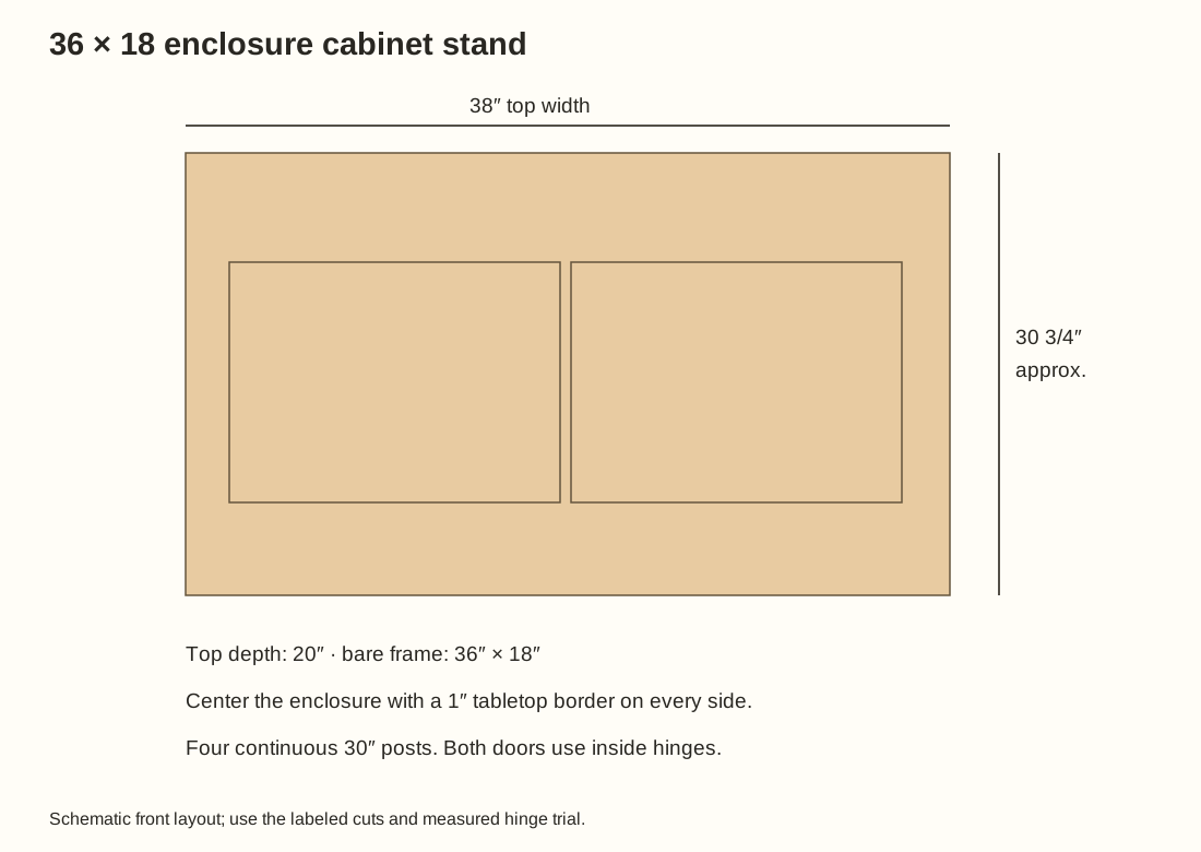
Fits 36″ × 18″ enclosures · 38″ × 20″ top · approximately 30 3⁄4″ tall
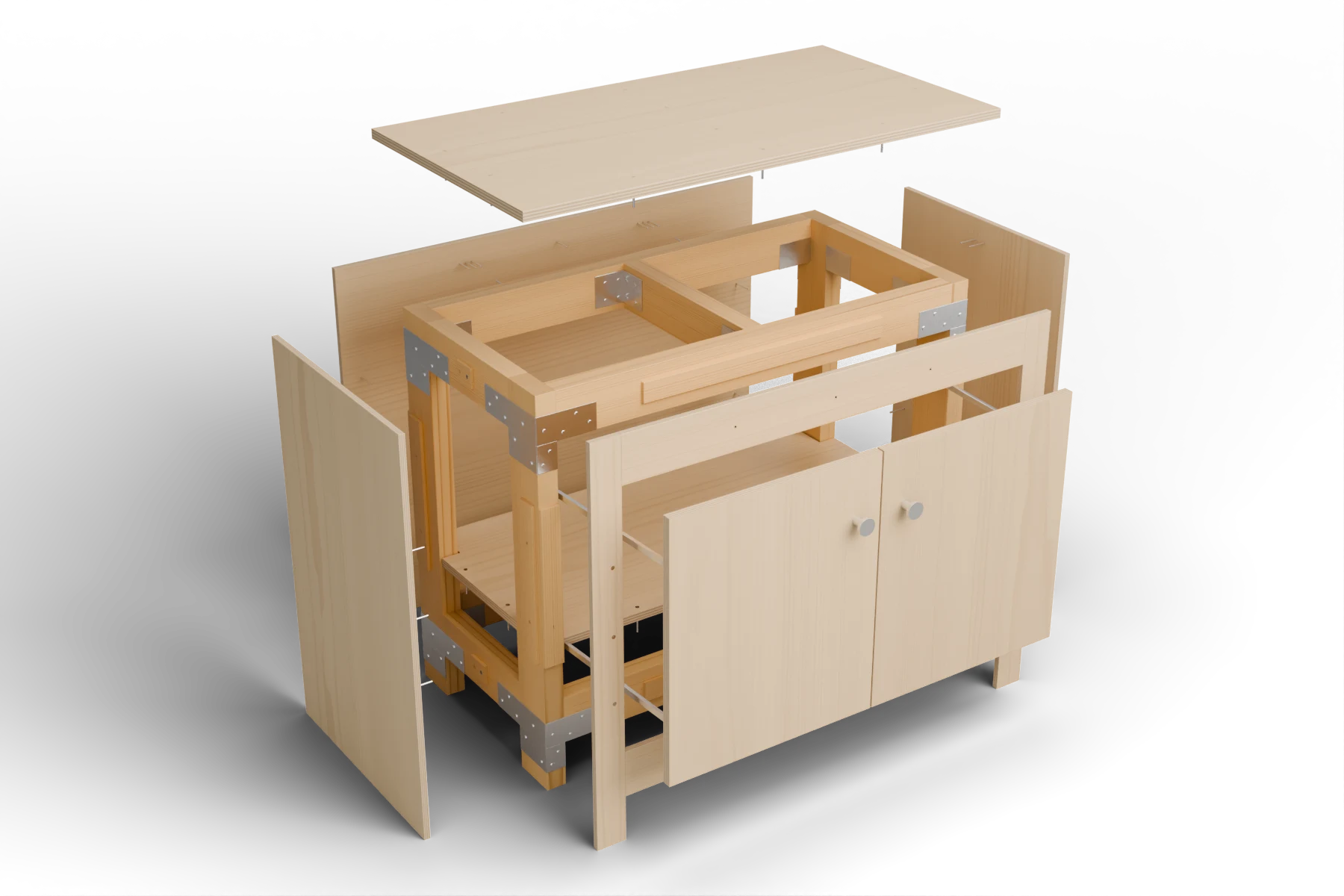
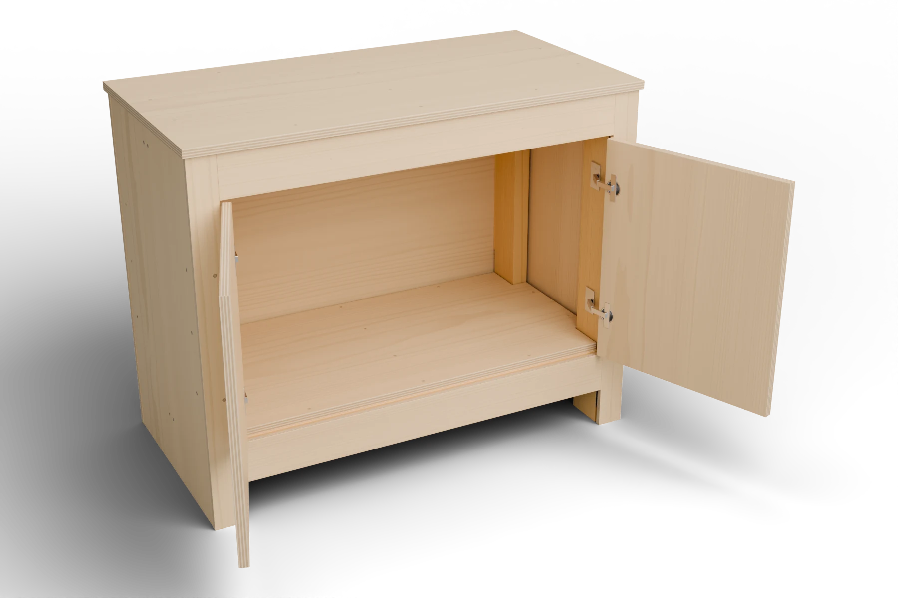
Two inset doors · concealed soft-close hinges · continuous corner posts
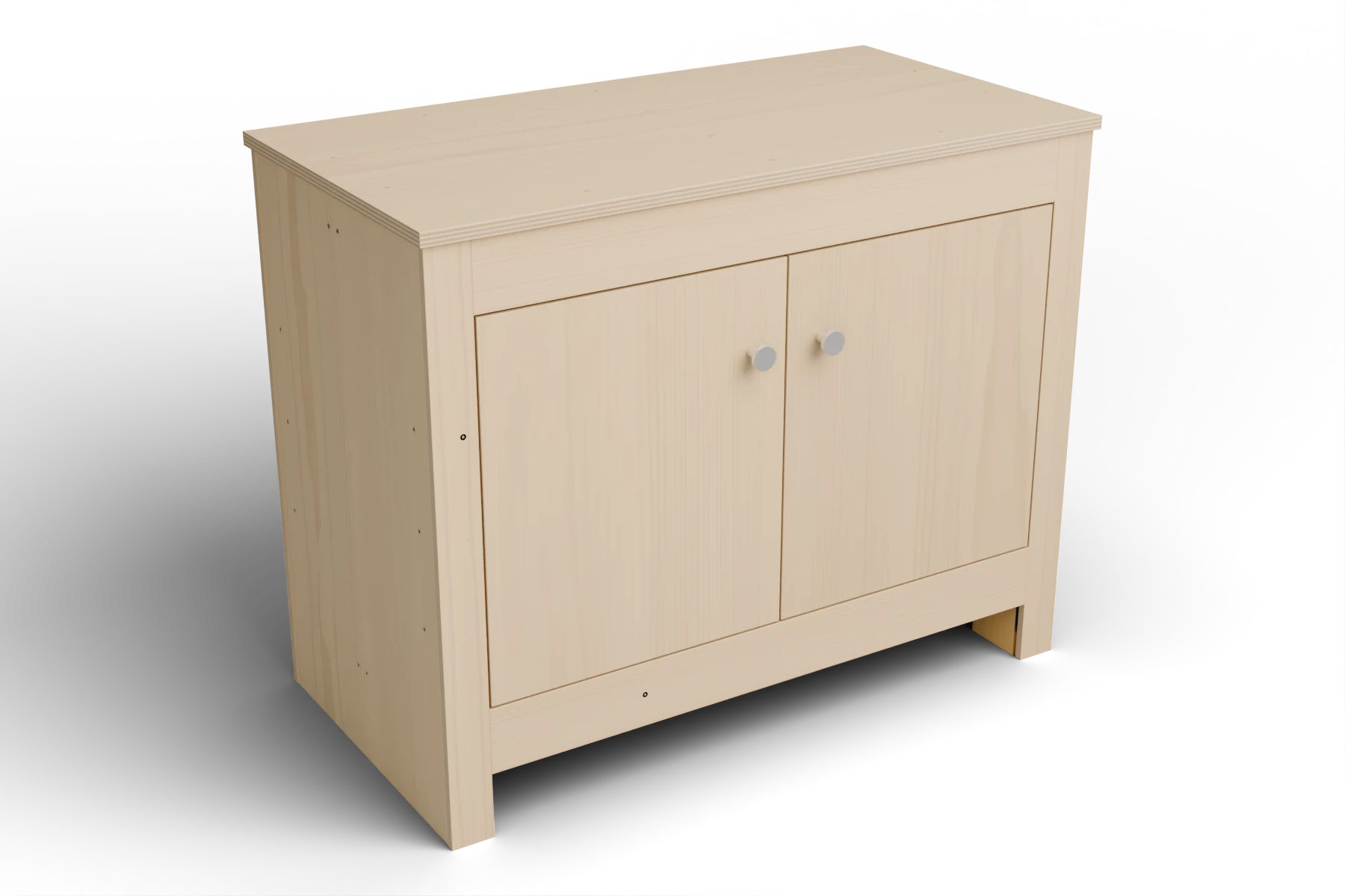
Build a wooden stand with a full support top and a useful cabinet below. Follow the labeled cuts, illustrated steps and interactive model from bare frame to finished cabinet.
Researched construction plan. Digitally checked; not physically built or load-certified. Generated October 2, 2026.
Check its required support surface, finished weight and ventilation clearance before buying wood.
The cabinet and enclosure are heavy. Arrange helpers and a clear route before lifting.
Finish all exposed wood and allow the product label’s full cure before loading.
Some shopping links may earn us a commission. Purchase quantities are listed below; retailer carts do not preset them.
| Screw | Head | Used for | Install | Buy | Clearance | Pilot | Depth |
|---|---|---|---|---|---|---|---|
| WBSK supplied #8 × 1 1⁄4″ | Wafer | RTC2Z corners | 96 | 100 included | Factory holes | Per kit | Per kit |
| Simpson SD9112 #9 × 1 1⁄2″ | Hex | RTA2Z center support angles | 32 | 100 | Factory holes | Per Simpson | Per Simpson |
| #6 × 1″ | Flat | Solid pine spacers | 32 | 100 | 9⁄64″ in spacer | 3⁄32″ | 7⁄8″ into frame |
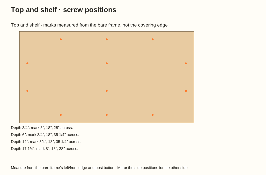
| #8 × 2″ | Flat | Top, shelf and covering | 68 | 100 | 11⁄64″ through panel/spacer | 7⁄64″ | 1 3⁄8″ into frame |
| Blum 606N #6 × 5⁄8″ | Flat | Hinge cups and plates | 16 | 100 | Factory holes | 3⁄32″ | 9⁄16″ into wood |
| #8 × 2″ steel | Pan | Stand-side restraint brackets | 4 | 6 | 11⁄64″ through panel/spacer | 7⁄64″ | 1 3⁄8″ into rail |
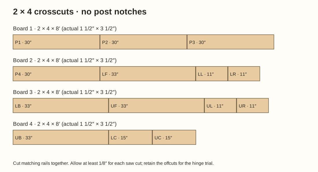
Board rows give the cut length; sheet rows give the two face dimensions. Stock thickness is in the group heading.
| Part | Qty | Size (in) | mm | Use |
|---|---|---|---|---|
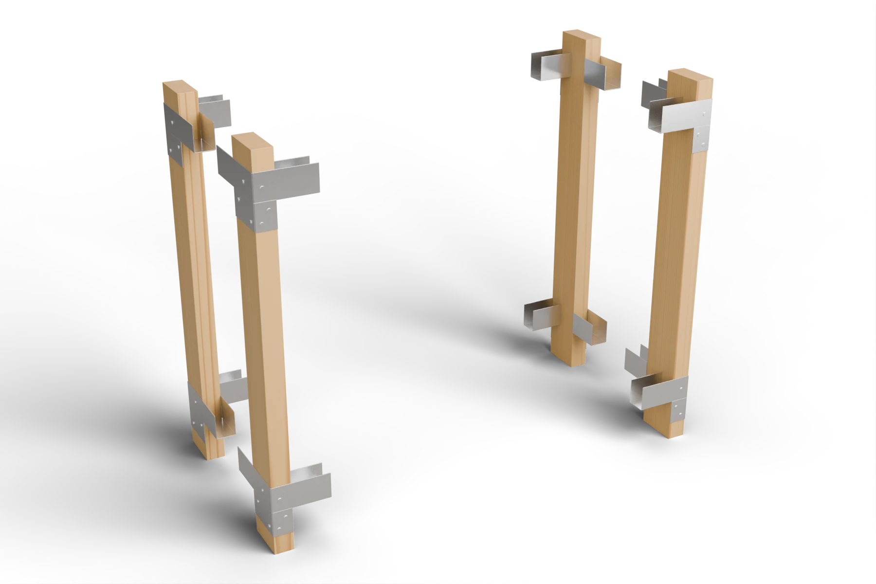
| P1, P2, P3, P4 | 4 | 30″ | 762 mm | Continuous corner post 1; Continuous corner post 2; Continuous corner post 3; Continuous corner post 4 |
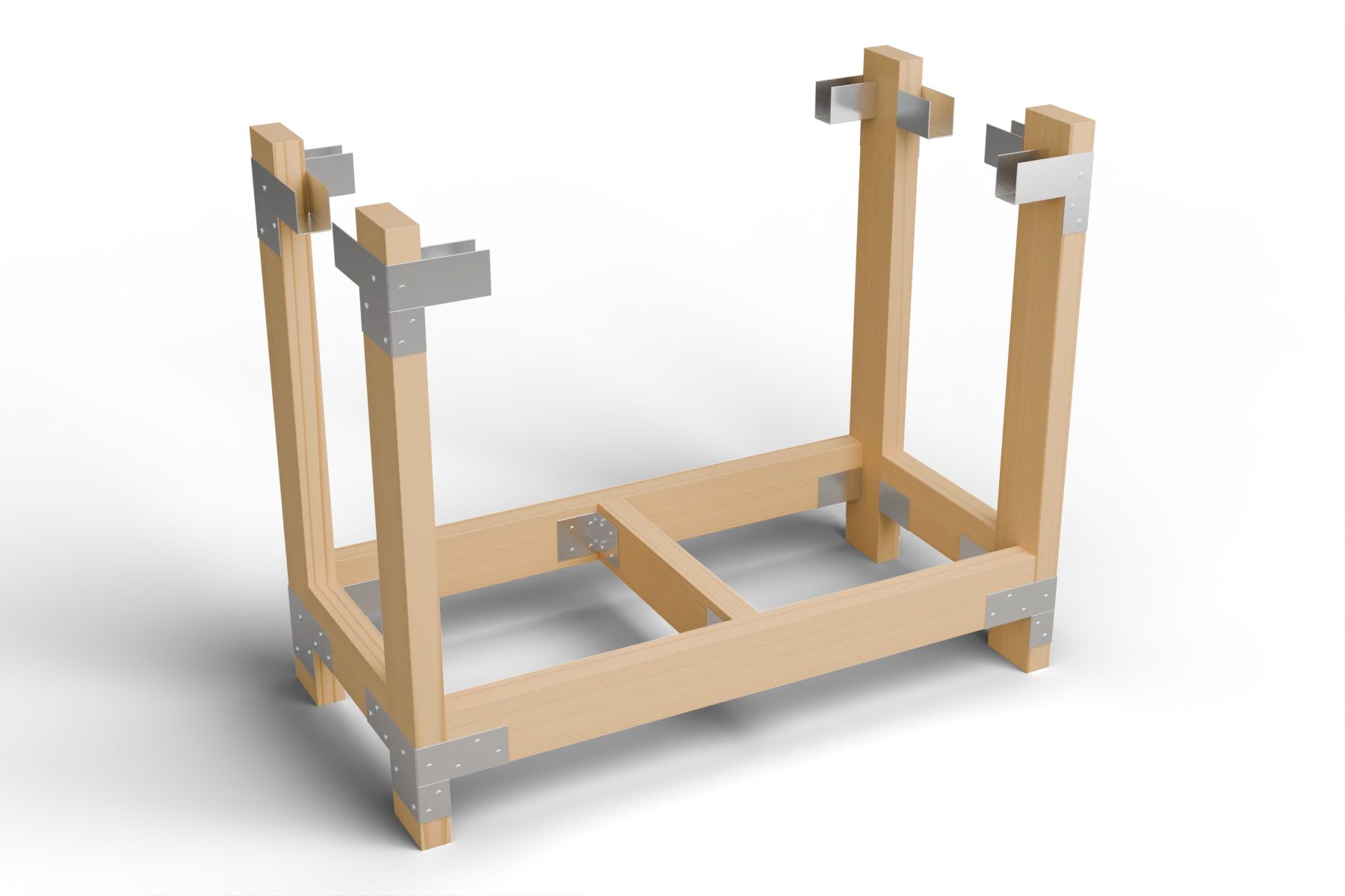
| LF, LB, UF, UB | 4 | 33″ | 838 mm | Lower front rail; Lower back rail; Upper front rail; Upper back rail |
| LL, LR, UL, UR | 4 | 11″ | 279 mm | Lower left end rail; Lower right end rail; Upper left end rail; Upper right end rail |
| LC, UC | 2 | 15″ | 381 mm | Lower center support; Upper center support |
Board rows give the cut length; sheet rows give the two face dimensions. Stock thickness is in the group heading.
| Part | Qty | Size (in) | mm | Use |
|---|---|---|---|---|
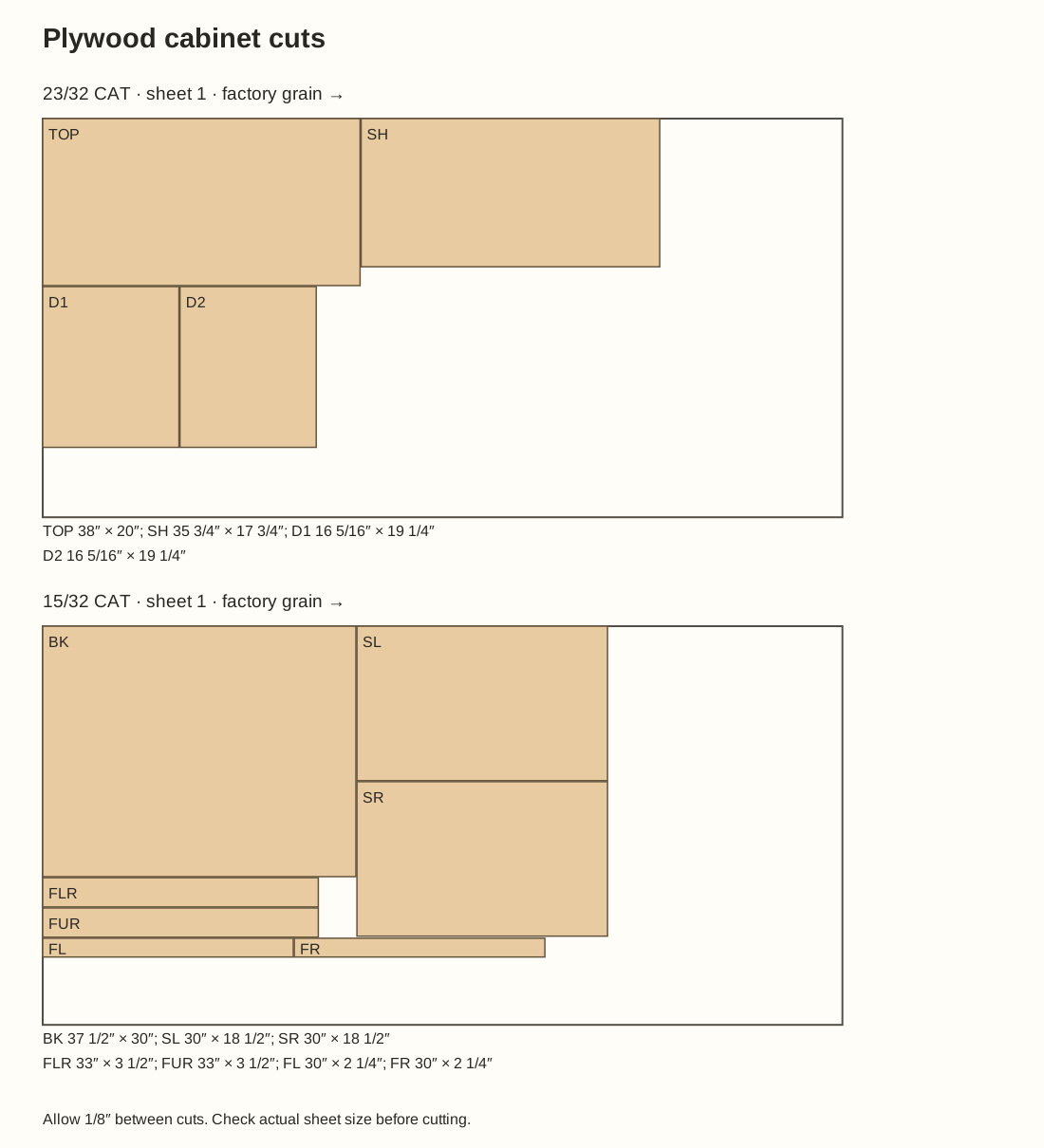
| TOP | 1 | 38″ × 20″ | 965 × 508 mm | Full support top |
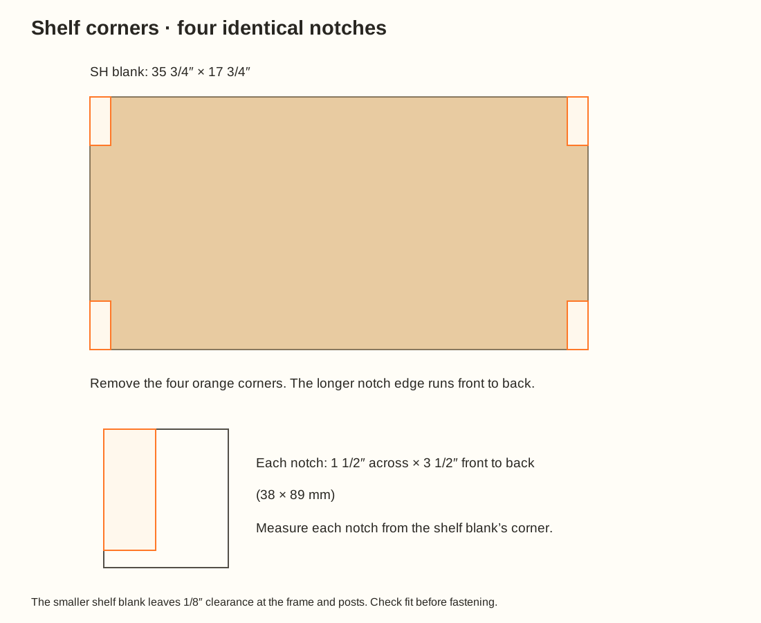
| SH | 1 | 35 3⁄4″ × 17 3⁄4″ | 908 × 451 mm | Cabinet shelf |
| D1, D2 | 2 | 19 1⁄4″ × 16 5⁄16″ | 489 × 414 mm | Cabinet door 1; Cabinet door 2 |
Board rows give the cut length; sheet rows give the two face dimensions. Stock thickness is in the group heading.
| Part | Qty | Size (in) | mm | Use |
|---|---|---|---|---|
| SL, SR | 2 | 30″ × 18 1⁄2″ | 762 × 470 mm | Left cabinet side; Right cabinet side |
| BK | 1 | 37 1⁄2″ × 30″ | 952 × 762 mm | Cabinet back |
| FL, FR | 2 | 30″ × 2 1⁄4″ | 762 × 57 mm | Left front trim; Right front trim |
| FLR, FUR | 2 | 33″ × 3 1⁄2″ | 838 × 89 mm | Lower front rail cover; Upper front rail cover |
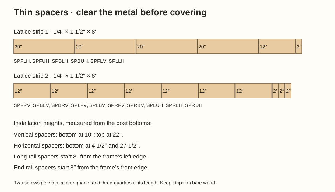
Board rows give the cut length; sheet rows give the two face dimensions. Stock thickness is in the group heading.
| Part | Qty | Size (in) | mm | Use |
|---|---|---|---|---|
| SPFLV, SPFRV, SPBLV, SPBRV, SPLFV, SPLBV, SPRFV, SPRBV | 8 | 12″ | 305 mm | Front left vertical spacer; Front right vertical spacer; Back left vertical spacer; Back right vertical spacer; Left side front vertical spacer; Left side back vertical spacer; Right side front vertical spacer; Right side back vertical spacer |
| SPFLH, SPFUH, SPBLH, SPBUH | 4 | 20″ | 508 mm | Front lower rail spacer; Front upper rail spacer; Back lower rail spacer; Back upper rail spacer |
| SPLLH, SPLUH, SPRLH, SPRUH | 4 | 2″ | 51 mm | Left lower end-rail spacer; Left upper end-rail spacer; Right lower end-rail spacer; Right upper end-rail spacer |

Step 1 of 15 · Phase A
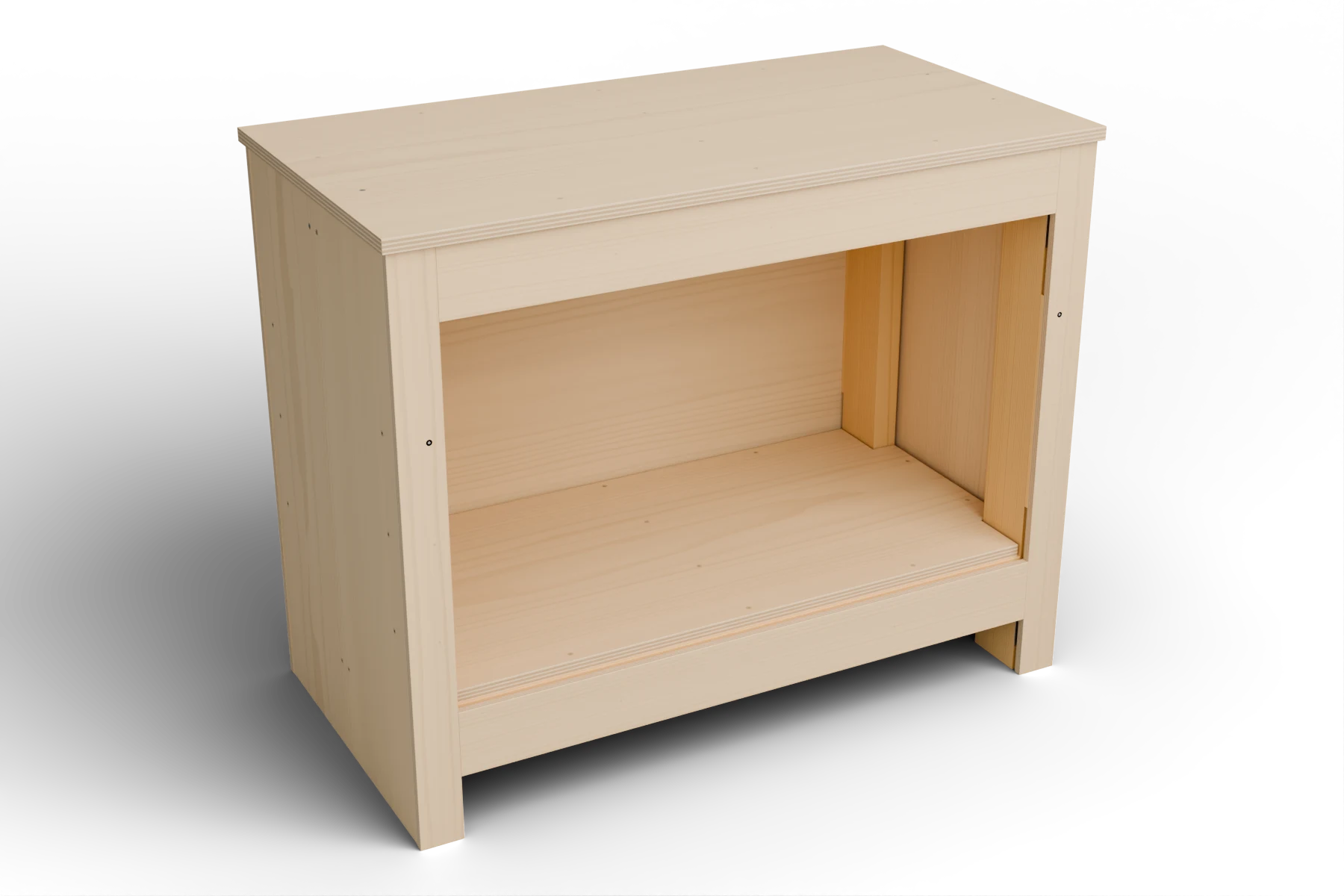
Allow room for both doors to swing open.
Step 2 of 15 · Phase A
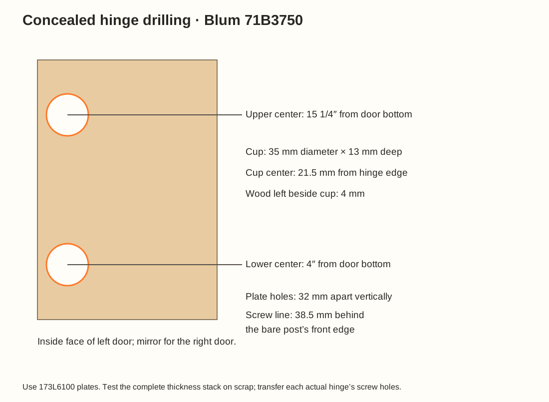
A small offcut test prevents expensive door mistakes.
Step 3 of 15 · Phase A
The cutting diagrams give a length for every board.
Step 4 of 15 · Phase B
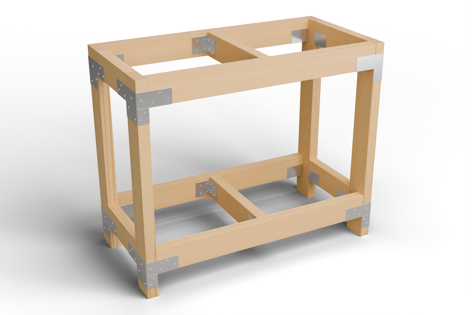
The four posts remain one piece from top to floor.

Step 5 of 15 · Phase B
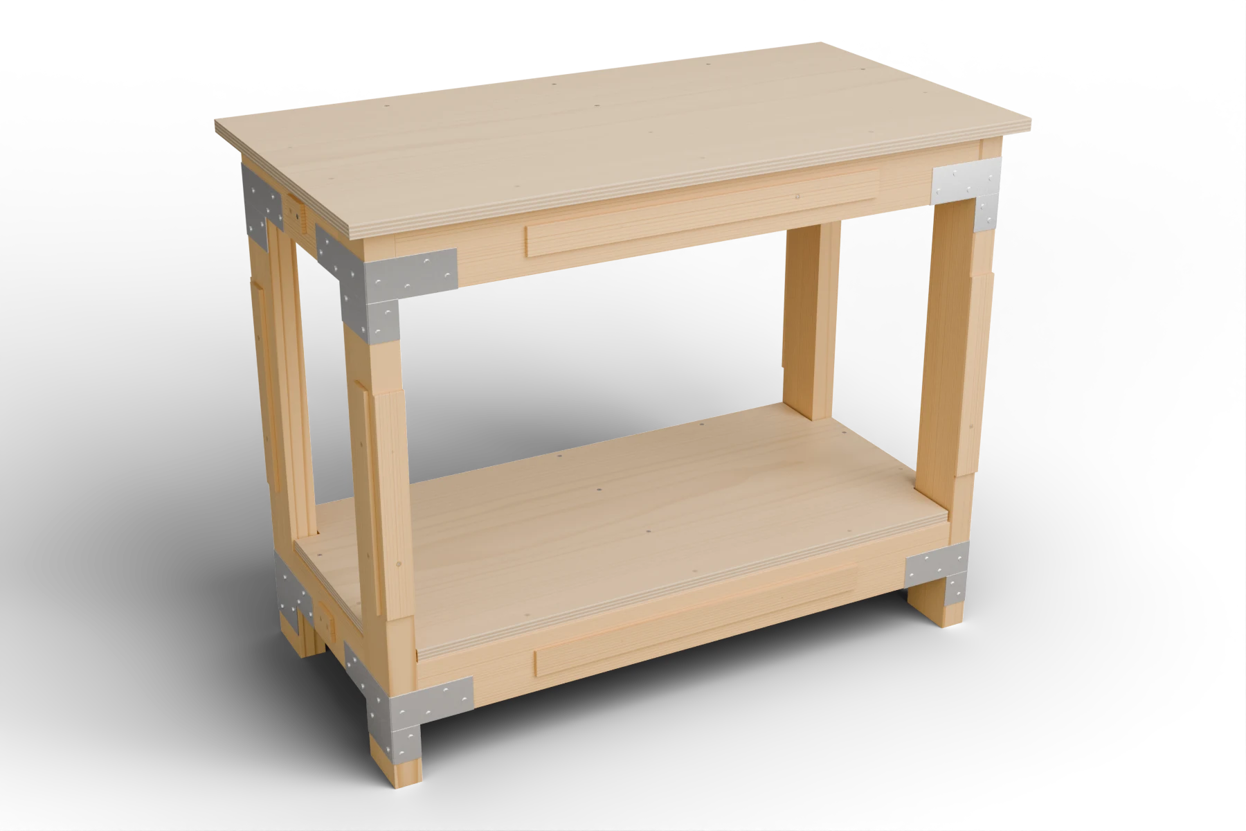
The lower shelf rests on the rails and center support.

Step 6 of 15 · Phase B
All upper surfaces must form one flat support plane.

Step 7 of 15 · Phase B
These thin strips keep the plywood clear of the metal connectors.
Step 8 of 15 · Phase B
Keep the top fully supported and free of raised screw heads.

Step 9 of 15 · Phase B
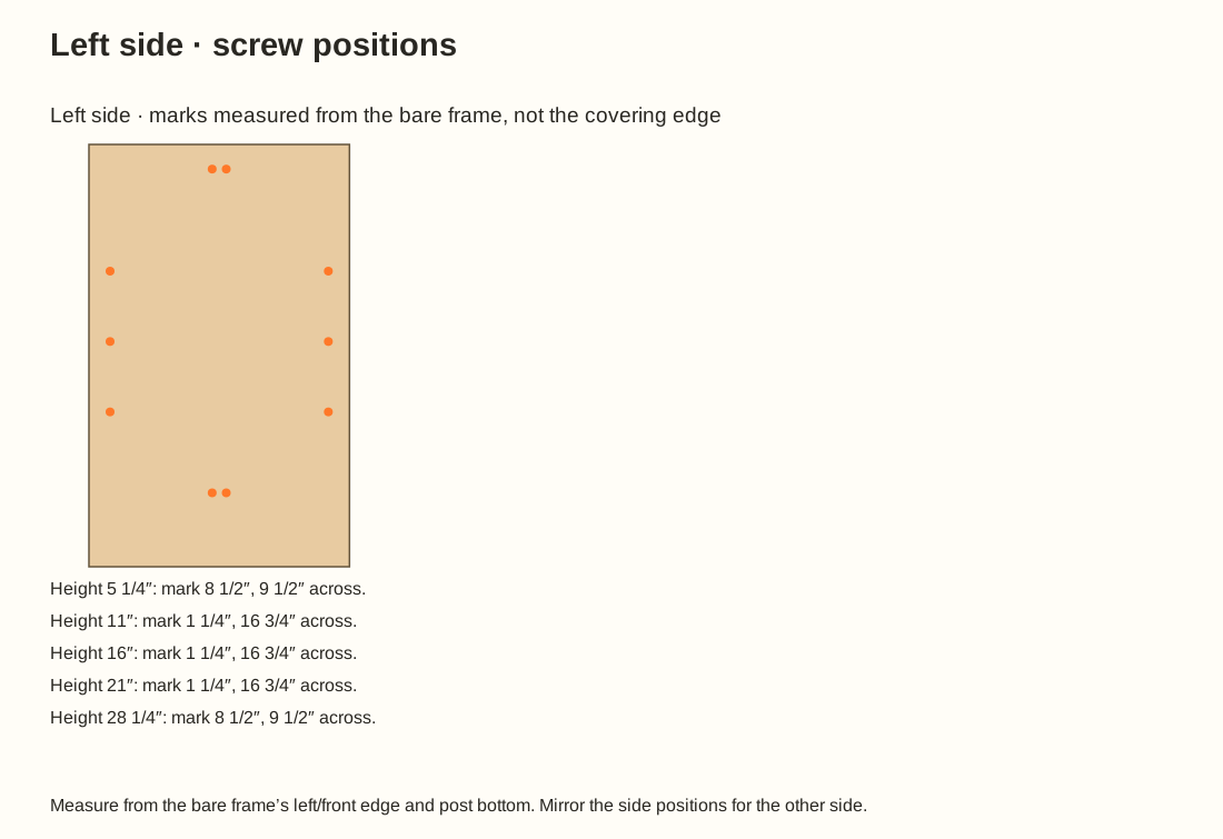
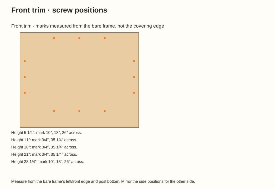
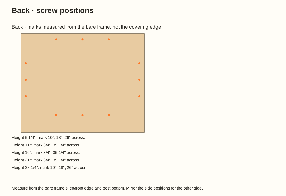
The back and side panels also keep the cabinet square.

Step 10 of 15 · Phase B
Finish the loose doors on both faces before hanging them.
Wait: 7 days minimum full cure; longer outside label conditions

Step 11 of 15 · Phase C
Use the tested jig from step 2.
Step 12 of 15 · Phase C
Both hinges and mounting plates stay inside.

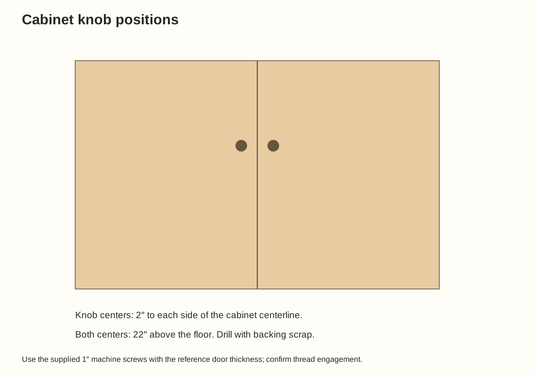
Step 13 of 15 · Phase C
A simple pull opens each door without a key.
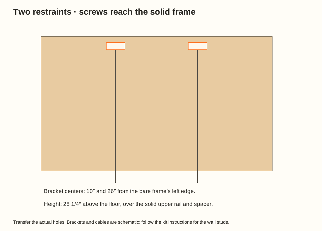
Step 14 of 15 · Phase C
Anchor it before loading or leaving the doors unattended.
Step 15 of 15 · Phase C
Load gradually and keep the weight spread across the flat base.

Support the door before releasing either hinge.
The plywood reference thicknesses are 0.703″ and 0.453″, from Georgia-Pacific. They are material specifications, not extra saw-cut instructions. Measure the received sheets and repeat the hinge trial if the stack differs.
Use the original hardware’s factory holes. Connector and hinge shapes in the model explain assembly; they are not drilling templates or manufacturer CAD.
The planning ceiling assumes a centered, flat enclosure base with evenly distributed weight, dry No. 2 Southern Pine, Group 1 plywood, every specified connector screw, full cabinet sides/back and installed wall restraints.
The review checks the upper rails, plywood and connector reactions. It does not certify the finished stand, workmanship, floor or wall attachment. No aquarium or stacking approval is implied.